Week 3: Three-Axis Gyroscope Print and 3D Model Scanning
3D Printing
The first part of today’s assignment was to understand all about the process and limitations of 3D printing. One of the most important aspects is probably the structure of overhang and supports - in the FDM (fused-deposition modeling) process that most of us have access to, supports can only be built in the same material as being printed, overhang angles are limited, and unsupported material can cross only short gaps.
I soon realized that this made the prompt of
design and 3D print an object that could not be made subtractively
a lot harder than it sounds, because what we’re actually being asked to do is make something that satisfies that, but also falls under the necessary support constraints. So we can’t just take any 3D body and print it (unless using another process such as powder bed.)
I looked around for some ideas by browsing the Thingverse, at which point I saw a picture of a gimballed gyroscope that looked like it could have been printed as one piece. I immediately realized the print could be relatively thin, but expand to a much more interesting three-dimensional form. Because our assignment is to design the object from scratch, I didn’t look into any more of the details - making mistakes is part of the fun!
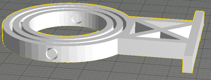
Matt Carney provided an excellent intermediate tutorial on SolidWorks this week, and explained his master modeling technique for properly managing parametric relationships between different parts. This is an incredibly useful workflow, and I took the first part of it as the base for this assignment, which is to create sketches for all of the main structural shapes first:
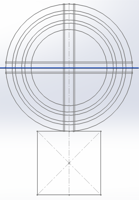
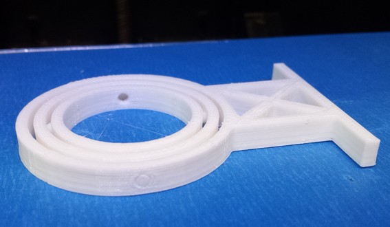
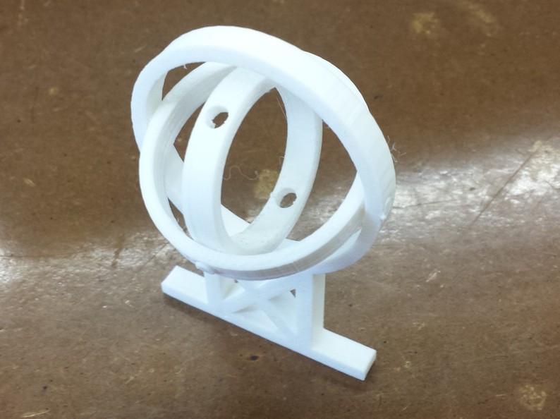
At a high level, the gyroscope has three gimbals that are concentric rings, with shafts that are 90 degrees offset for each inner layer. The picture shows the print orientation, but if printed correctly the gimbals should be able to rotate immediately out of the printer. The tricky part here is to make sure the shafts are not actually stuck to the rest of the structure, and are strong enough to break any bonds with their enclosing holes.
Rob Hart found last
year
that a shaft clearance of 0.01 in was sufficient for clearance
between straight edges. This turned out to be too small for circular
objects, as we’ll see below.
An important part was the addition of fillets to the gyroscope shafts. This served several purposes. First, the fillet helps support the part of the shaft which is above empty space, as it is built up at an angle. Second, it allows the shaft to self-center when it is being rotated. Finally, it strengthens the shaft.
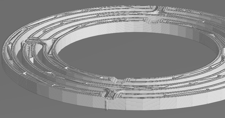
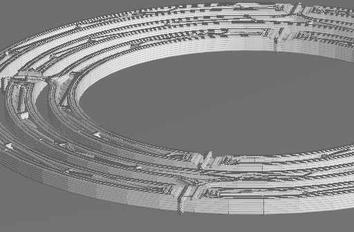
Below is a picture with layers from the initial print of this
gyroscope, computed from the 3D printing app. You can immediately see
that at the low resolution of 0.03 in, the shaft and the rest of the
structure look like they are going to be stuck together. This preview
is generally very helpful for diagnosing such issues.
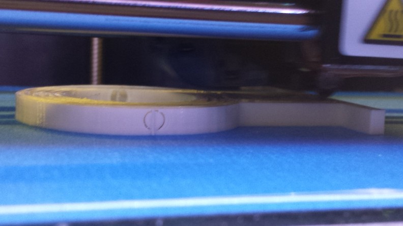
I went ahead and printed anyway, because at this point I didn’t know what wouldn’t work. Here’s what it looks like at around the same point while printing. At this point you can see the shaft is pretty much being fused to the frame.
This is the final product. No amount of Exact-o knife trickery is going to get that bearing to rotate.
At this point, I made a few changes to the model. First, I increased
the thickness of the shaft to strengthen it, as it would need to break
free of the hole. Second, I increased the clearance from 0.01 in to
0.02 in. I also printed the model with supports, so that the bottom
of the shaft would not be completely attached to the hole, and
increased the printing resolution from 0.03 in to 0.02 in
vertically. This would help with making the shaft more round, as it is
built up in discrete layers. The increased resolution increased the
printing time from 35 to 50 minutes.
You can see the supports that are automatically added by the software here, at the lowest layer before the shaft even starts to appear. This will help the shaft to be suspended in the right place as it is printing.
During the printing process, the clearances look a lot better, and the supports are helping the shaft stay in the right place.
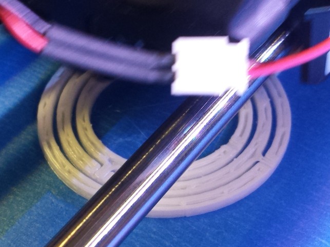
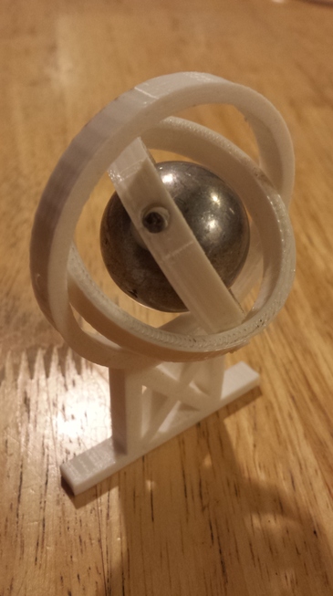
After breaking off the support structure, the gimbals can rotate right out of the printer! The structure is pretty rigid, and can’t be disassembled into its separate bodies. It’s a good example of something that can’t be done (very easily) subtractively.
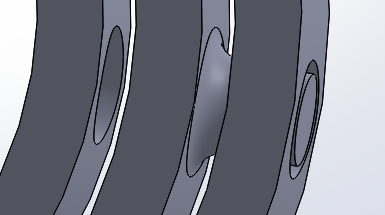
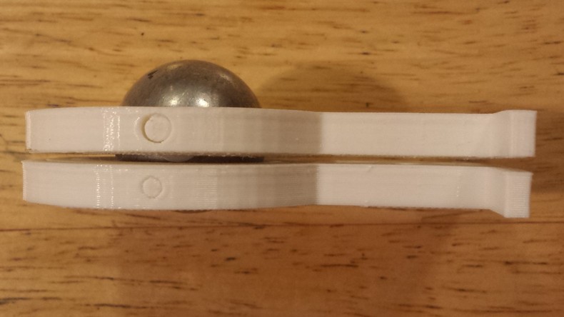
Here’s a comparison of the shafts for the first attempt and the second one. The latter does its job, while the former is a complete mess of fused plastic. Getting the tolerance right is important.
For fun, I inserted an object with high rotational inertia into the center of the gimbals, so it could fulfill its purpose as a gyroscope. This isn’t exactly a precision mechanical instrument, though, and I wouldn’t depend on it for navigation in any long sea voyages.
3D Scanning
For this part of the assignment, I’m going to go over a laborious journey of turning a 3D scan into something that is actually usable for CAD modeling.
We are using the Sense scanner, which uses a technology that stitches together images of an object, taken at different angles, into a single point or mesh cloud. All you have to do is wave it around. Sounds, simple enough, right?
Well, there are some caveats. My first attempt was to scan a mug with a handle. It turns out that this technology is not great for objects with rotational symmetry, as there aren’t enough features to identify which angle the object is being scanned from. During the scan, multiple handles started appearing on the mug at different angles, and I abandoned this after a few tries.
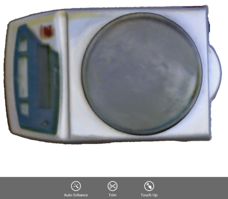
I decided to scan a scale I found lying around in the shop instead, which doesn’t suffer this problem. The Sense scanning software offers some basic functions to clean up the mesh from the scan, such as trimming off unwanted portions and smoothing out local regions. It’s not too powerful, though, and we’re going to have to do the brunt of the work elsewhere.
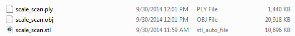
There are multiple file sizes that the scanner software outputs, and as you can see, they vastly differ in size:
Mesh Cleanup
At this point I turned to SolidWorks for working with the mesh. Our
student edition includes the ScanTo3D toolbox which comes with
SolidWorks Premium, and has the features below. I know people have had
success with MeshLab and Rhino for working with 3D scans, but I
actually wanted to go to a CAD model that I could modify, and hence
took an experimental plunge into using SolidWorks’ less-tested
tools. As of 2014, SolidWorks doesn’t like opening big .stl files,
but is happy to work with .obj files.
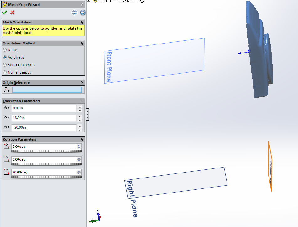
The first step in SolidWorks is to clean up the mesh. Solidworks doesn’t actually recognize a mesh as a surface, which are parametric regions that can be used for modeling. There are many steps to actually get there. We start with the mesh prep tools, which first allow us to align the mesh correctly with respect to the origin:
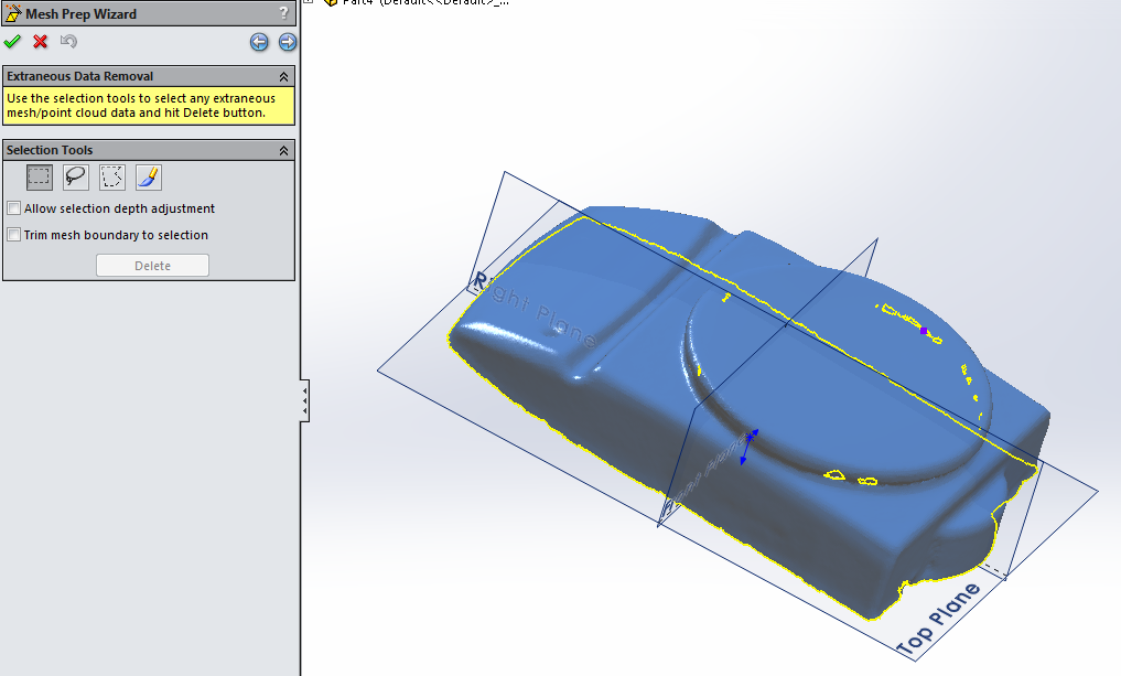
Then, we trim off any extraneous parts of the mesh. It actually came out pretty cleanly from the scanning software, so there isn’t too much to do here.
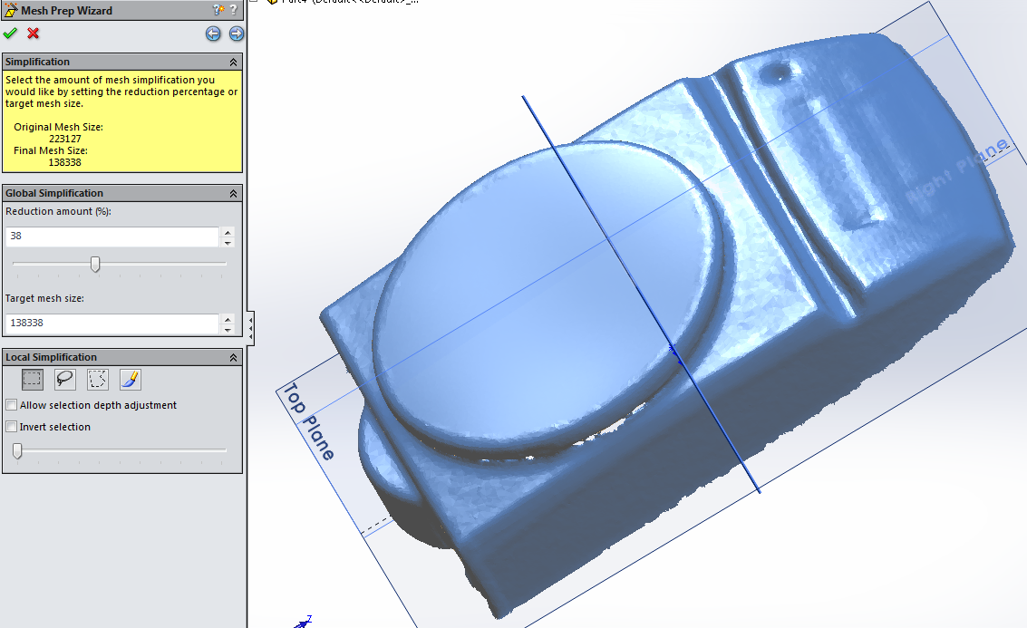
The next step is a simplification phase, which reduces the number of triangles by locally combining them. This makes the features coarser, and you can do it both globally and locally.
Immediately after simplification, we are given the option to do smoothing, which perturbs the orientation of triangles but not actually geometrically modify them. This helps make apparent flat regions actually flat instead of “bumpy”. The scale surface above is an example of smoothing that I did before in the scanning software.
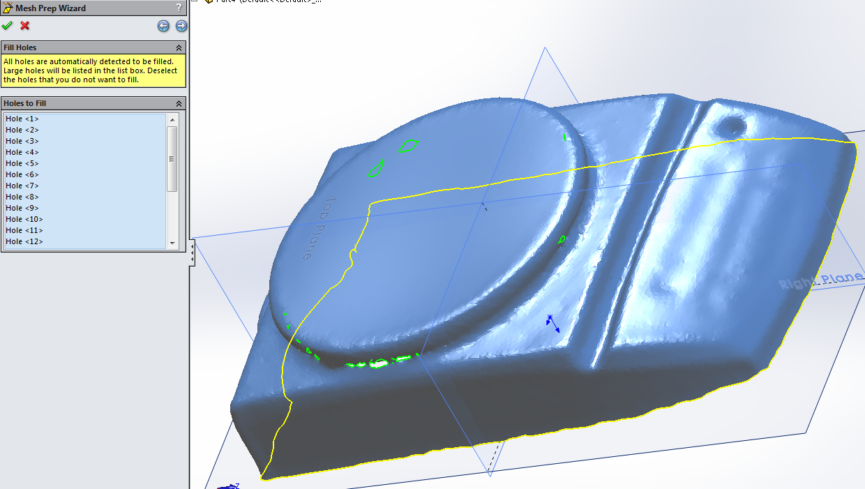
The last step is to fill holes in the mesh, which SolidWorks seems to be able to recognize and patch automatically.
Now that the mesh is cleaned up, we can move on to one of two methods for generating a surface that can be eventually turned into a solid model.
Automatic Surface Generation
The first option is for SolidWorks to generate local approximations to the overall surface using parametric forms that are appropriately trimmed, then knitted together. This is recommended for “organic” objects that don’t contain precise geometric shapes.
This process is extremely CPU intensive, and took a while even on my desktop with a 4.4 GHz Core i7-4790K, and used a lot of RAM - even on the low detail settings. It then produces a surface with self-intersections and other errors.
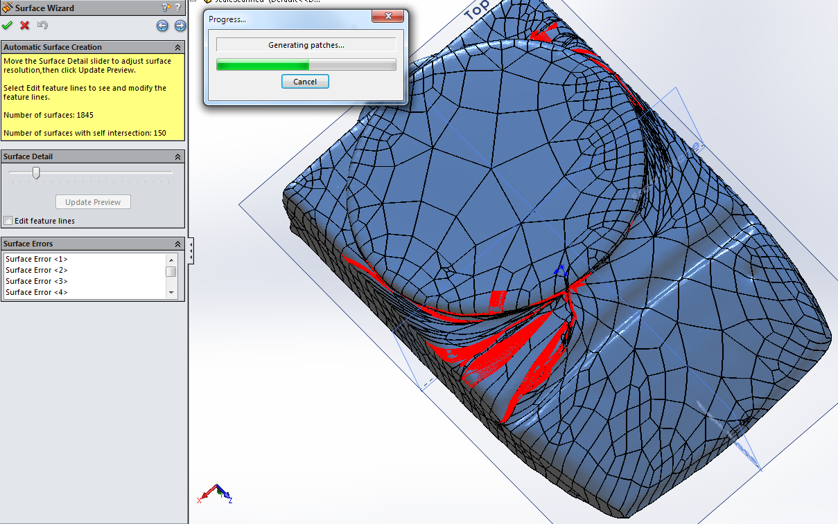
As you can see, the approximate surface is great if you are trying to model a banana, but isn’t too helpful for actually doing further design.
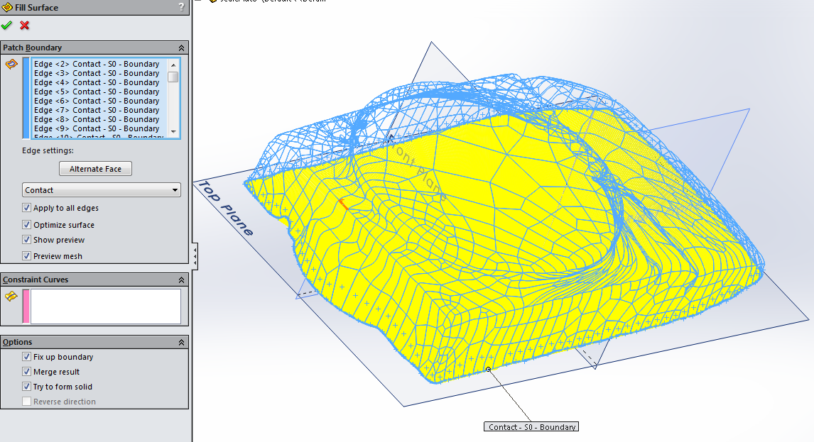
After this, I tried closing the surface into a solid object by using the edges at the bottom, but couldn’t get it to do so agreeably. Seems tantalizingly close, though.
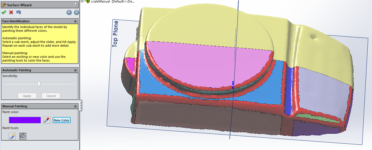
Guided Surface Generation
The alternate method is to manually generate surfaces using parametric representations, then to trim and knit them together. Starting from the mesh again, the first step is a semi-manual painting where surfaces are identified by different colors. You have to help SolidWorks out here a bit. I’m using an option here to only work with half of the mesh, as it is symmetric and can ostensibly be mirrored later.
Next, each of the identified faces has a surface generated from it. Most of these are flat planes, but I also created some cylindrical surfaces for the edge of the top plate, and the protrusion on the rear.
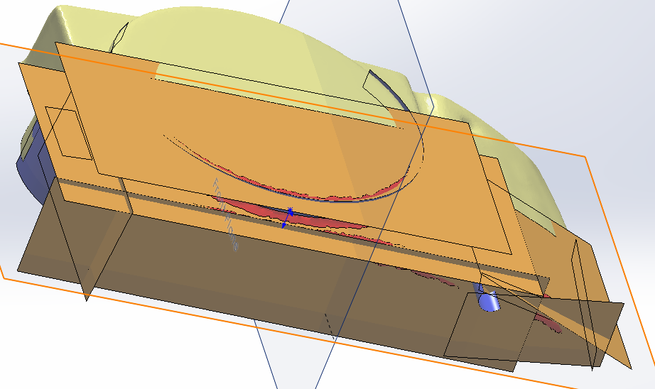
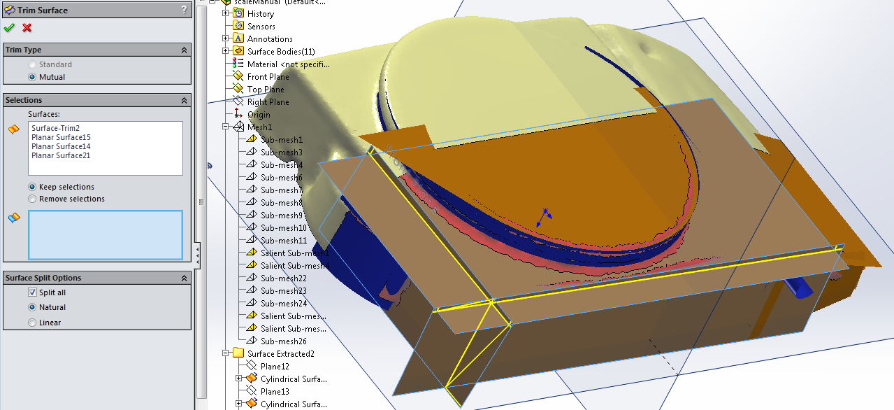
The next step is a pretty grueling process where all the intersecting
surfaces are used to trim each other using the Trim Surface
tool. This takes quite a while, as all intersecting surfaces need to
be used to trim each other. I also trimmed the bottom using a plane.
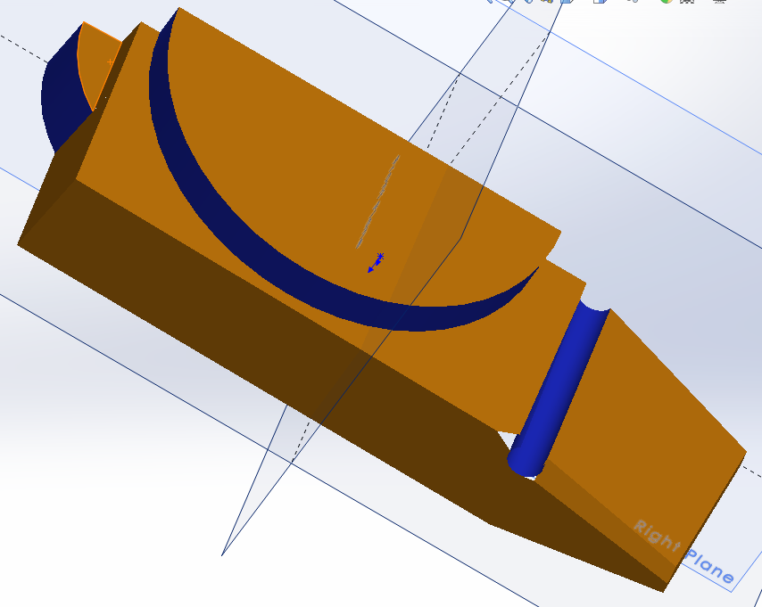
This is the final product, with most of the surfaces knitted together. The trimming intersections create “watertight” joints, but there are still some gaps due to the interesting geometry at the front. The next step would be to thicken the surface from the space contained by these surfaces and the two planes, and to mirror it across the axis of symmetry. Once the solid is formed, we’d add fillets to reclaim its original shape.
In my opinion, that was a lot of work to get a model where the right angles aren’t perfect, the surfaces probably don’t line up with the axes, and the symmetry is a bit off. For objects like these, it’s probably best to design them from scratch using measurements and sketching, rather than conversion from a 3D scan.