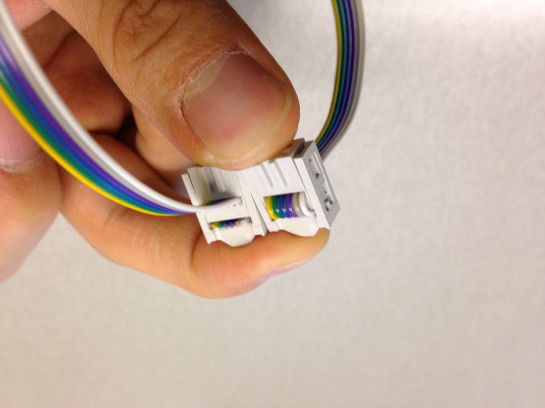
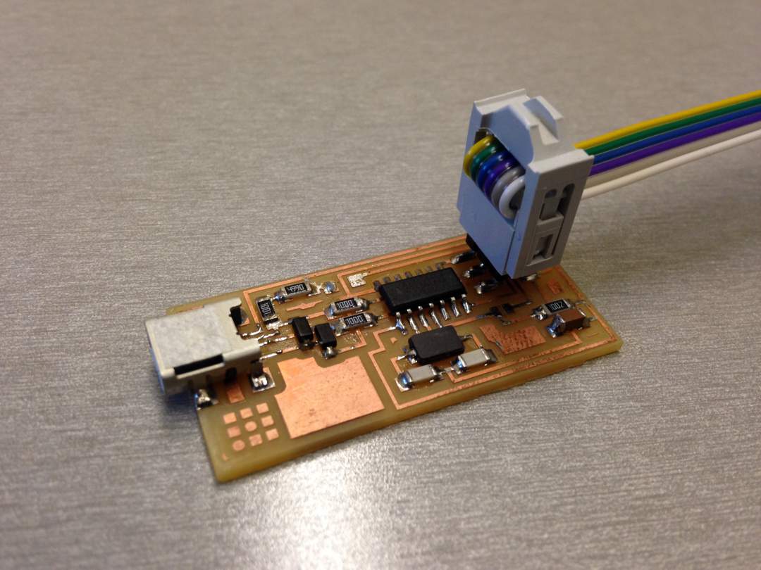
Step 1: Making 6 pins connector
We need 6 pins connector cable to connect FabISP and Echo board. Making those connector was pretty straight forward process but you need to make sure that orientation of both connectors are the same, and same pins of two connectors connect same color of cables.
Step 2: FabISP programming
I connected two 2x3 pins, connecting GND on non-programmed FabISP to GND on programmed FabISP. Then I connected programmed FabISP to my laptop using miniUSB-USB connector. To program FabISP, I followed tutorial 1, tutorial 2. I saved hello.ftdi.44.echo.c and hello.ftdi.44.echo.c.make file in a same directory, and run make clean, hex, fuse, and program command. In the beginning it seemed that I couldn't have installed avr properly. When I typed avrdude, I couldn't find avr itself. However, when I closed terminal window and open it again, everything went smoothly without any error messages. Fortunately I didn't have any issue on FabISP circuit itself. I desoldered zero ohm resistor and solder jumper.
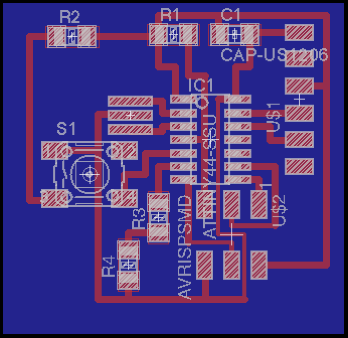
Step 3: Echo Board programming
I stuck at this process due to circuit board design failure. After I connected FabISP to my laptop with miniUSB-USB cable and supply power to echo board using FTDI cable, I run make. I refered It was okay, but I encountered “initialization failed rc = -1 something blablabla” error when I run make fuse. It turned out that I shorted GND to MOSI of 2x3 pins. In my circuit design, I didn't pput enough clearance between two wires so Modela didn't mill the part, and I didn't notice it. After I scraped the bridged section, I could have run make, make program-usbtiny-fuses, and make program-usbtiny. To understand C programming, this tutorial helped me a lot.
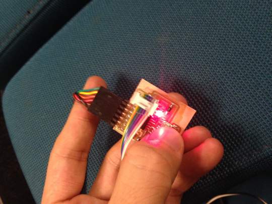
Step 4: Final product
LED was blinking!!!