I've always loved the aesthetics of Japanese paper lamps.

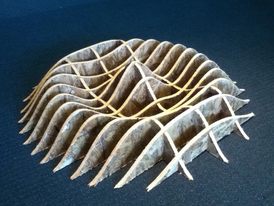
I had one of these in my room for a long time. However, recently, hen I moved, my lamp ripped, which caused me a great deal of sadness. When thinking about ideas for this project, the smooth, soft forms of these lamps came to mind. When browsing through the 2013 archive looking for inspiration, I came across Charles Holbrow's Make Something Big project page, and saw the smooth forms of the sine wave that he made:
Charles mentioned that he used 123D Make to parametrically slice up his part into sheets. Instantly, I knew what I should do.
I quickly mocked up the shape I had in mind in Rhino:
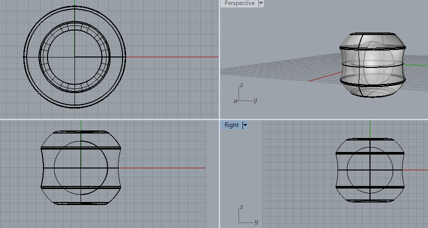
The side has a cutout to make the shape more interesting; the top has a cutout for sitting, and the bottom has a cutout for symmetry. A light source of some kind would be in the middle, to make it glow. In the final version, it would be made out of plywood and be used as a chair, glowing softly in the evening, but could be suspended for lighting up the room.
I exported the design as an STL and imported the file into 123D Make. I first tried the "interlocking slices" construction technique, but then realized that due to the radial symmetry of my object, the "Radial" option looked much better. I played around with the number of horizontal and radial slices until I thought it looked decent.

I then went to export the parts for cutting. (Austin helped me out immensely in this next section.) However, 123D Make was producing many different DXF files, one for each part. I started importing these DXF files into Rhino and arranging them in preparation for the MasterCAM workflow, I realized that all of the parts were very small -- millimeters in size! I wanted to just scale them up, but Austin thankfully pointed out that that would make the pressfit impossible, since the thickness of the material is physically fixed while the tabs would get bigger. I went back into 123D Make and realized that I could input both the dimensions of the material I am cutting into (48'' x 96'' x 0.465'' OSD), and the final dimensions of my object. I guessed that I want my chairlamp to be about 18'' in width. After typing this in, I discovered that 123D Make automatically arranges parts on your material! Thanks, Autodesk :-)
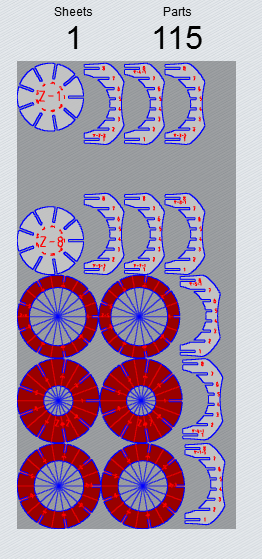
Throughout this process, 123D Make would highlight all of my parts with holes in them and color them red and complain. However, I saw no problems with the design it generated, and went ahead with it anyway. I think their error-detection algorithm has a bug.
The piece of OSB I had at my disposal had a chunk cut out of it in the top right hand corner. I had to carefully rearrange the pieces generated by 123D Make in Rhino to avoid the top right hand corner, and to be farther apart from one another (as 123D make had them almost touch in its setup). In addition, Austin told me that we had to put Rhino points on every sharp corner, because MasterCAM needs to use these points to drill holes on the corners so that the cutting process works better. Rather than drawing the points by hand, Austin whipped up a python script to select every segment of length $0.455$, which was the width of the pressfit slots, and turn it into a different color. However, we could not get it to work, until I tried modifying the script to put in a range of lengths for segments. This worked very well, although it selected two incorrect segments. Unselecting those and doing Divide/MarkEndpoints finished the job. Yay, Turing!
MasterCAM was a pain to use. There were three cutting runs to generate: one to cut the holes in the corners, one to cut out the pieces leaving only a few millimeters holding them to the stock, and a remachining pass that, after clearing edges up, would then remove the pieces from the stock. One issue I had was that I did not orient the inner curves of the circular parts properly, so MasterCAM offset these curves to the wrong side. However, I thought that it should not matter, because if all the inner curves were offset the same amount, the ball would still look good.

The Onsrud machined quickly; it took about 30 minutes for the job. The toolpath was a little bit screwed up -- in the second pass, it spent some time moving the large drill over all the holes drilled in the first pass without doing anything. (The "Brushes Up" button is very useful for debugging!)

So much (Ons)crud!
Finally, when the dust settled, I looked at my pieces and realized that having the inner sections of the rings be offset incorrectly caused a problem. The remachining step that removes the onion-skin layer on the bottom does not hug the curve on the right side, and so leaves a chunk of onion-skin attached ot the main work. Luckily, this is only a prototype of my chairlight, and no one can see the details of the inside anyway! Lesson learned: always offset correctly.

Assembly was straightfoward. Placing the second and third vertical struts in was frustrating due to alignment issues, but once they were in the system was properly constrained and the rest of the pieces slid right in.
I used a mallet to make the piece fit together snugly.
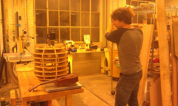
My friend tests the construction. The chair is a little swivelly but seems very stable. Maybe it would be fun to remachine this out of nice plywood, taking the time to fix the offset issue, probably removing a horizontal strut (for aesthetic purposes), find either a nice hipster-looking bulb or some nice programmable LEDs, and put them into the lamp.