Programming success
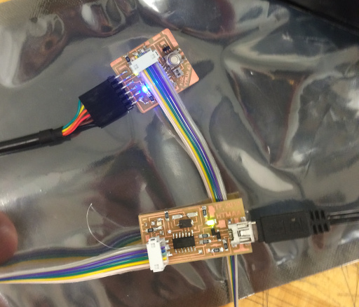
I started out by reviewing the ATtiny44a datasheet, specifically the fuse configuration. I found this site to be a really useful resource for what the fuses were all about. A quick summary of what I found: There are 3 bits for selecting the type of clock (CLKSEL[3:1]), and 2 bits for selecting how fast the microcontroller should startup on reboot (SUT[1:0]). Best I can tell from the datasheet, the slower the microcontroller starts up the more stable things are, as the oscillator takes some time to stabilize. I decided to go for the most “robust” settings, which is “1” (unprogrammed) for all CLKSEL and SUT bits. In Neil’s example code, he has the microcontroller program the CLKPR register to set the clock divider to 1. Turns out, there is a fuse that deals with this (CKDIV8). If you leave it unprogrammed (1), it the clock should start undivided at startup. In my case I made the lower fuse programming byte BF as I also wanted to enable the clock out fuse. For programming, I decided to go with straight GCC as I've messed with Arduino before and I thought it would be better experience to work with the low level tools a bit. I installed the avr-binutils avrlibc avrdude all from MacPorts. I used the makefile and hello.echo code from Neil's examples. Interestingly I had to modify the makefile in order to get things to work correctly. The Avr-size command complained about a command line argument (-mmcu setting), so I just deleted all the command line arguments and it compiled fine... Definitely not a case of doing things because I understand what was going on, but it fixed the problem. Thankfully my board programmed with my FabISP made a few weeks back, and I was able to talk to the board (running the echo code) over the FTDI serial, a success!
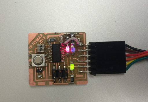
A horribly modded board, but hey, blinky!
Next I did a bit of hackery with my board. I had a design error with my original board. I had put two LEDs on the serial data lines, expecting them to only light up when data was being transferred, but I overlooked the fact that the serial lines are idle high (5V) instead of idle low. This made it so the LEDs stayed on all the time and only barely blinked with data transfer. After hearing Neil talk in class about how it was normal to hack boards up a bit (and not wanting to resolder an entire board), I decided to go for the hackish approach. I cut the ground lines, flipped the LEDs around, bridged the previous ground of the LEDs with the 5V trace, and added a jumper to complete the ground. I wasn't particularly skilled with this. For example, I broke a resistor, and then when I added new resistors, managed to put in the wrong value (499k ohm again instead of 499 ohm). This basically meant my board took a beating. It looks pretty terrible, and the LEDs are pretty pitifully weak even with the downgrade of resistor value from the first design, but hey it works. In this case I opened the terminal and banged on the keyboard to send some characters to the board while taking the picture. The blue LED represents low level (data) on the host->board TX line, while the red LED represents low level on the board->host TX line.
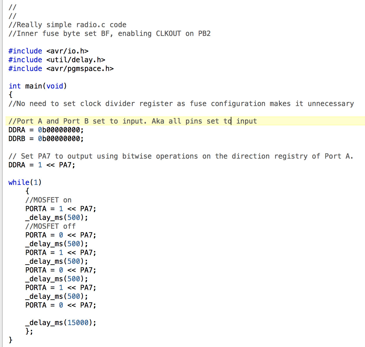
My simple code to "blink" the radio
After verifying that the board could program and doing the bit of modding, I decided to get to work on my program. Neil's example was a bit confusing, as it actually was a pretty complex program doing a software serial interface. All I wanted was to toggle some pins, which I couldn't quite figure out from Neil's examples. After some searching, I found this great resource for pin toggling AVR basics. In short, there are things called "Ports", which are collections of 8 pins. Each port has a few bytes of memory in registers, and bit 1-8 corresponds to pin 1-8 of the port. In order to do things with the pins, you have to set the particular bit of the pin of the register to what you want. You can do this "directly", for example, if I wanted to set pin 5 of Port A "on" I could do (I think): PORTA = 0b00001000. A trick is to use bitwise math. PORTA = 1 << PA7. This moves the "on" bit into the right position. I haven't looked into it too closely, but I think this approach would set all the other bits to zero. A better approach would be to use an bitwise OR plus the bit shifting to ensure things that are "on" stay on. Anyway the code tries to send an "S" in Morse code, which I chose as this was the message sent for the first transatlantic communication by Marconi See bottom for text file of the actual C code.
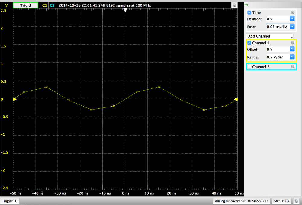
Periodic signal seen with Digilent Discovery
After uploading the code, I checked to see if getting a periodic signal which was turned on and off by the MOSFET. Happily I did see a signal, in the form of a sine wave which was triggering every 15 seconds (as per the code). Above is the trace from my Analog Discovery demonstrating this. In short, the Analog Discovery is like an oscilloscope, but much cheaper but still moderately capable. That being said, 20MHz is kind of the limit of what it can measure, you can see that the samples in the picture are getting a little sparse. In actuality, I'm unable to determine just how "clean" a sinewave this is due to limitations of this instrument.
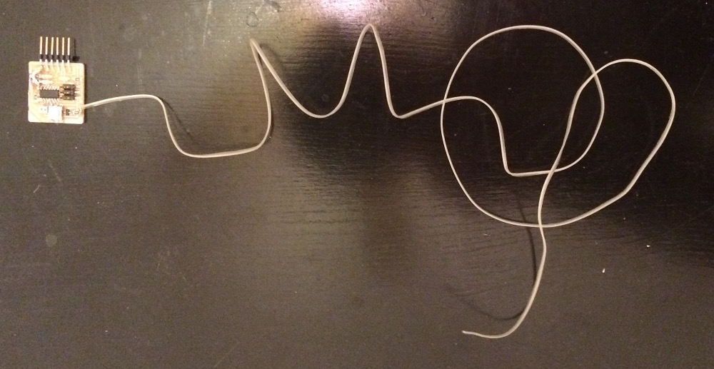
Board + antenna
The board + antenna in all its glory. Built to exacting specifications, definitely not a hacked together burnt mess with barely soldered braided wire for an antenna.
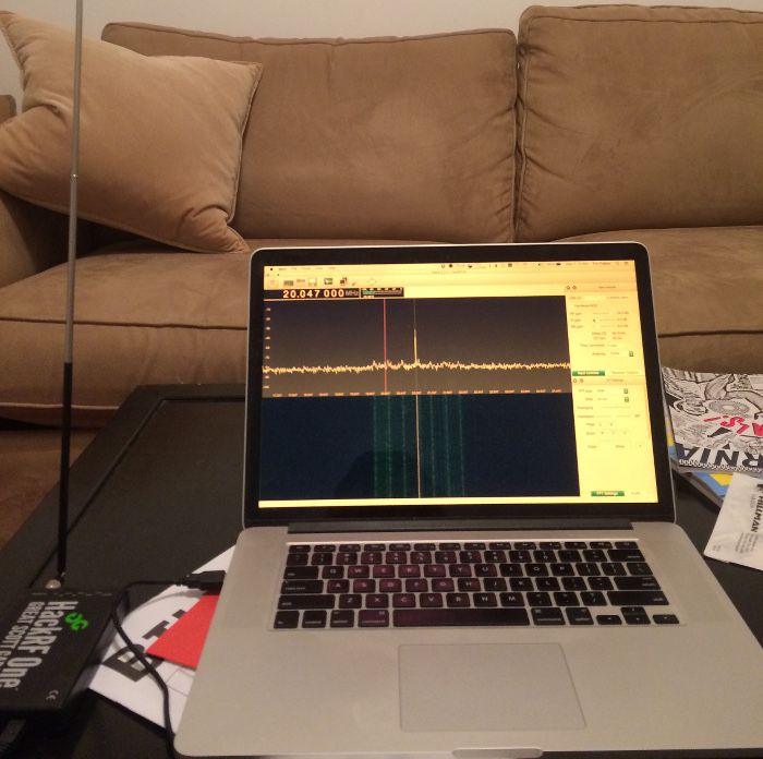
Cutting edge software defined radio for receiving 1900s style signals
A picture of the testing setup. Laptop connected to HackRF software defined radio peripheral. The HackRF is a low-cost general radio transceiver, from 10MHz to 6GHz, which is quite remarkable. If you're unfamiliar with software defined radio, it really is one of the neater technological things to happen within the past few years. The analogy is this: at one point, everything to do with audio manipulation was hardware. Then, technology developed, sound cards and digitization came along, and now you can do really sophisticated effects with audio with a general front end (USB microphone into a laptop), and post-processing in software (autotune, for example). Software defined radio (SDR), is the same concept, just with radio signals. The idea is to have very general radio front-end hardware, then do all the processing on the computers. One SDR transceiver can be a GPS reciever, a FM radio receiver, a AM radio reciever, a bluetooth receiver. The list goes on, its a very powerful concept, and its a lot of fun to get a SDR and poke around and see what signals are on the air. The most entry level SDRs are just $30. In my case, I'm using the HackRF, which isn't $30. Regardless, I'm using it as an simple AM radio receiver at 20MHz, trying to tune into the signals the 20MHz driven ATtiny would be giving off from its makeshift antenna.
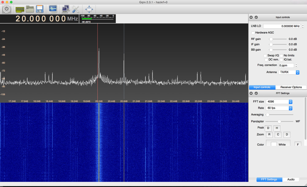
Spurious signals!
Holy spurious signals batman! Granted this is from having the board and antenna basically right next to the HackRF, but this is gnarly stuff! I'm also pretty certain these aren't intermodulation artifacts from the HackRF, as all the gain settings are set way down. Curiously the main signal seems to be just upstream of 20MHz. I'm unsure whether this discrepancy is resultant from inaccuracy in the crystal resonator on the board, or from inaccuracy of the oscillator within the HackRF. But importantly, in the waterfall plot you can see the 3 blips indicative of successful radiation and reception of my board produced "morse code" signals. The board is a real on-off-keying transmitter!
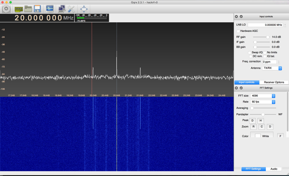
Spurious signals!
But from how far can the signal be detected? I put the board all the way on the other side of my (small) apartment, and tested again. The primary 20MHz signal is still clearly visible. The waterfall above demonstrates me turning on the board, a unambiguous difference between noise and signal presence can be seen. Despite this signal, there isn't a clearly visible 3-blip signal like in the example above. However, when you turn on AM demodulation of that primary carrier, the signal is clearly audible. I've linked the .WAV file demonstrating this. A warning, the audio is basically static, be sure to turn down your speakers before listening as it is a bit abrasive. Overall a pretty neat experiment! Curious to play around with simple radio a bit more. Perhaps its not as difficult as it would seem? That being said, I don't think I achieved the extra goals of the week too well. Our assignment was to program the board in as many languages and environments as possible. I did only C. In the future I'd like to mess around with assembly / hex a bit, as well as the Python on a chip Neil mentioned in class. Files for posterity