Entering into overly complex routing hell
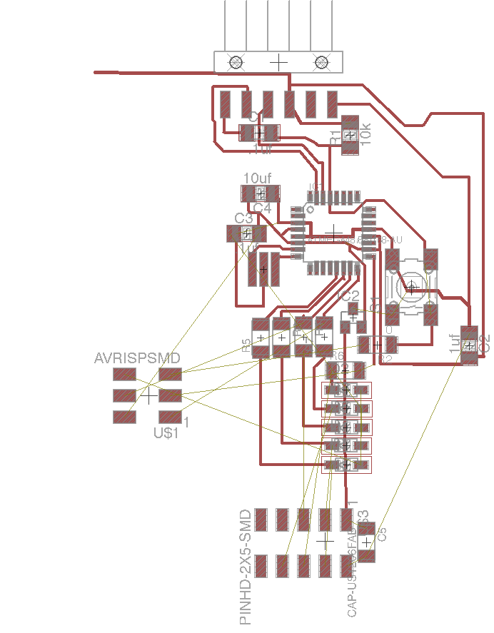
After choosing the nRF24L01 radio module as my networking apparatus of choice, I did some research on the available software to drive it. This is a very popular part in the Arduino ecosystem, and thankfully Arduino has a very helpful page on the existing software. There was some Attiny support, but it all seemed linked to Arduino in some way. I had been previously programming my boards with a purely C, gcc, makefile, avrdude toolchain, so I decided in order to use the software that existed for working with the nRF24L01, I needed to dive into the Arduino ecosystem. With that, I left behind the familiar Attiny44a and started planning to make a AtMega328 based "fabduino", which beyond having the software of the Arduino ecosystem behind it, has great features like programming over the serial port with a bootloader, more flash, more ram, and greatly more pins. Above, you can see the (not so) great start I got off to: I tried to simplify the fabduino board design from the FabKit I/O so it didn't have all the extraneous I/O pins and instead had pins for the ISP programming as well as the nRF24L01 module. Additionally, the nRF24L01 requires 3.3V to run, which means I needed level shifting from the 5V Fabduino, as well as a 3.3V regulator. The alternative is to run the whole Fabduino off 3.3V, but given that I didn't have a 3.3V programmer, I discounted this option. In the end, the logistical problem of getting all the pins correctly connected proved to be too much, and I moved to a "3D" approach.
Ditching the layout, a multi-board design.
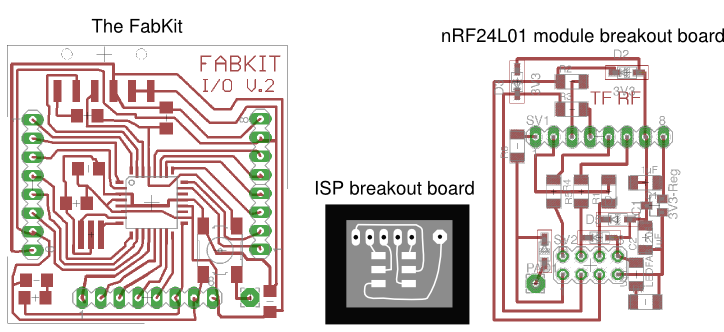
Routing, while a fun exercise, is best done in manageable chunks. Due to that, and because modularity and reusability is good, I decided to use the bog standard "FabKit" fabduino board, along with a small board just designed as an ISP breakout board, and a 3rd board designed to interface with the nRF24L01 (which is on its own board!) The third board has the most interesting things going on: I added a 3.3V regulator to power the nRF24L01, as well as an assortment of 1k resistors and 3.3V zener diodes to level shift the microcontroller 5V SPI communications down to the level that the nRF24L01 can handle. The milling went "okay". A few traces broke off, and the central section Modela seems miscalibrated such that 1 edge of the board will be cut deeper than the other (even with extremely careful taping / cleaning of the sacrificial layer). However, as the next picture will demonstrate, the FabKit I/O design seems quite "sub-optimal", with a naive usage with FabModules causing multiple shorts.
The ISP breakout board and the FabKit board
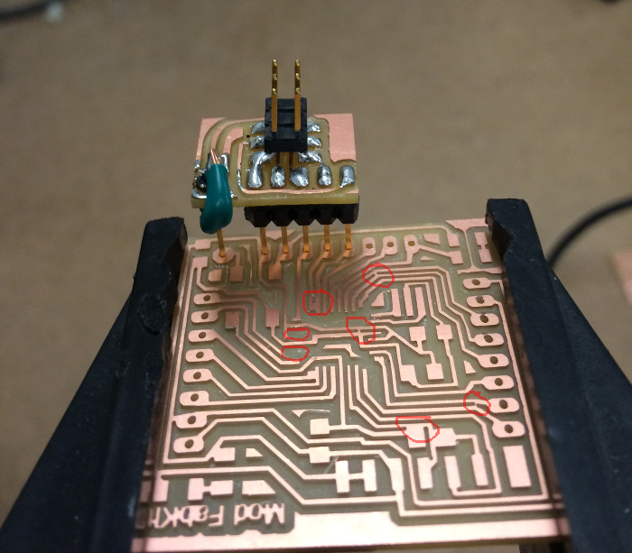
Barring some trouble with making sure the header pins were electrically connected to both the ISP breakout and the FabKit pads, and the hassle of soldering / desoldering when you want to program, this breakout board was a passable solution for interfacing pins. The alternative seemed to be using a hacked ISP cable, which seemed like an even less elegant solution than the breakout board to me. Unfortunately, in my case the FabKit board was not meant to be. Circled in red in the picture above are all the milling flaws on the board. A few key pins broke off (analog ground), but importantly multiple traces were shorted due to the design. This was due to insufficient clearance between multiple traces, which lead to Fab Modules merging traces in the path planning. I am very impressed by whoever made the FabKit, that level of routing is a lot of work, especially with the time given to learn all this stuff. However, they didn't follow through with the details. The traces are routed in a bit of a haphazard way, some are too close, some take unnecessary turns, and most frustratingly from an OCD perspective, the angle of some of the traces are just a hair off of parallel to the grid. Beyond being unsightly, this characteristic actually led to the shorting of VCC in GND in the traces underneath the processor.
High voltage parts desoldered
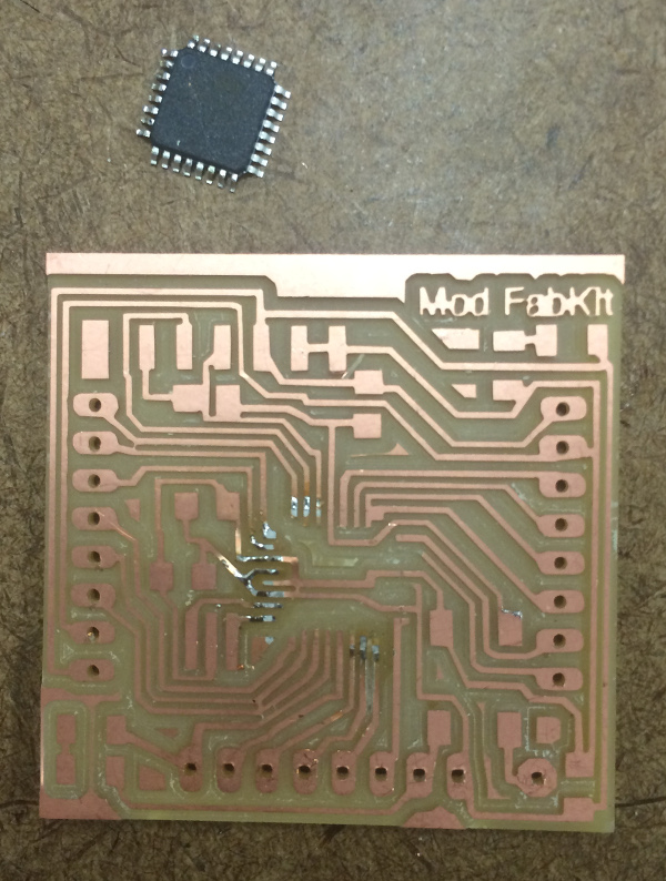
Of course, I noticed all the milling flaws after soldering on the AtMega328. I then took the heatgun, which removed the chip, but also melted the adhesive for the traces, thereby making the board almost impossible to resolder on. I decided to start from scratch, fix up the design of the FabKit, and mill a new board.
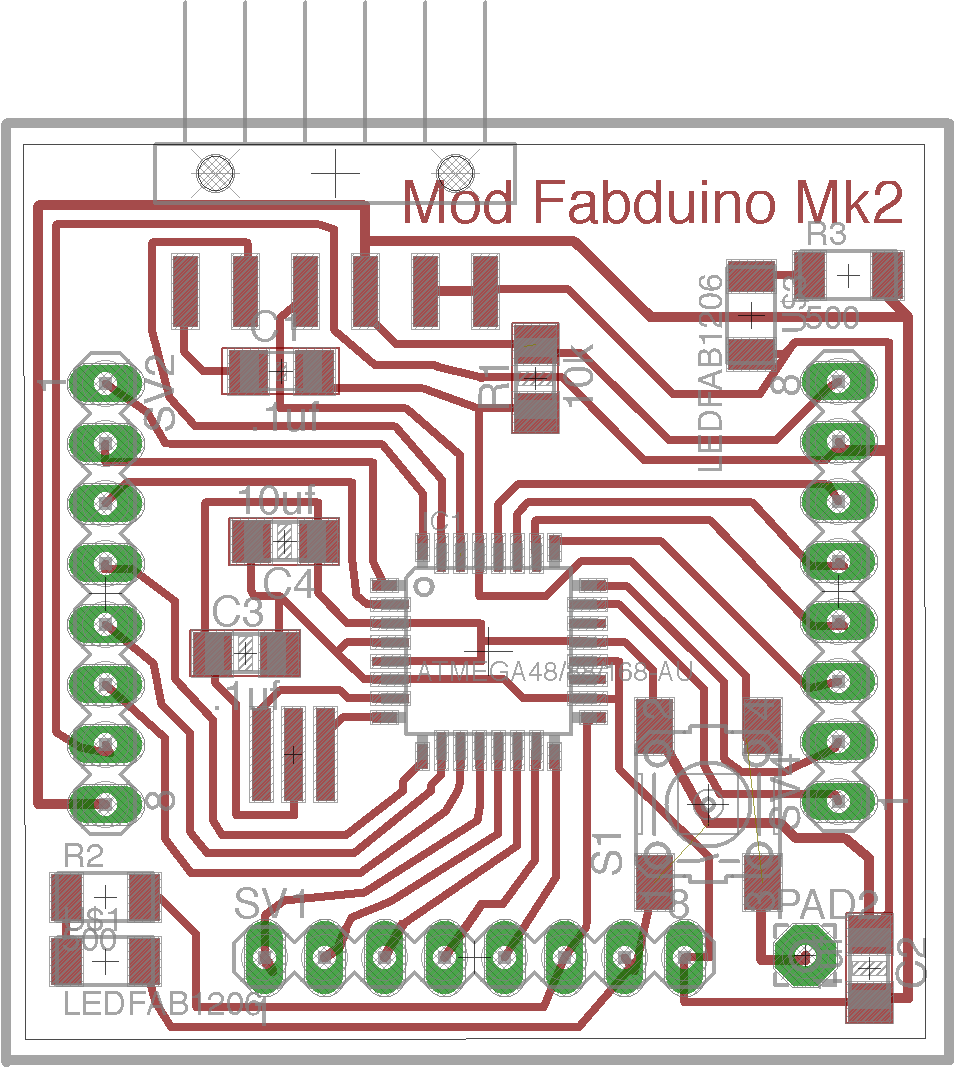
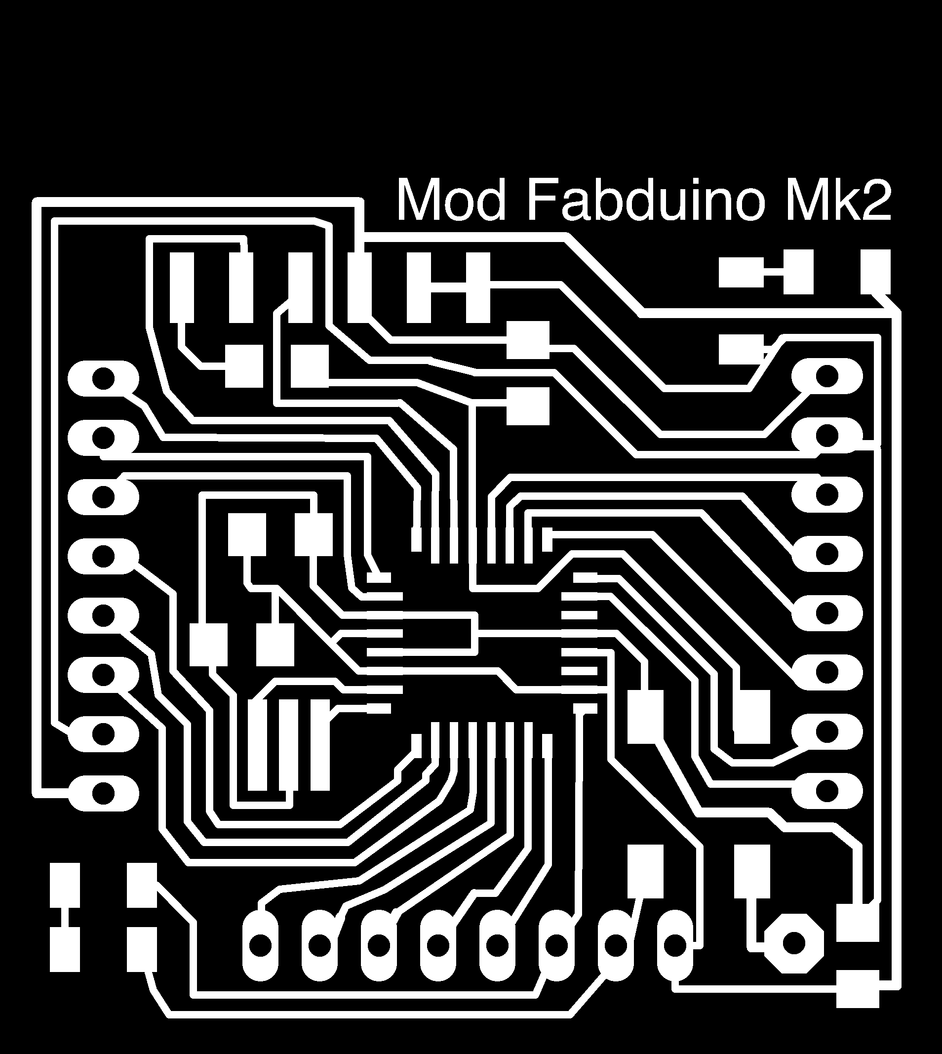
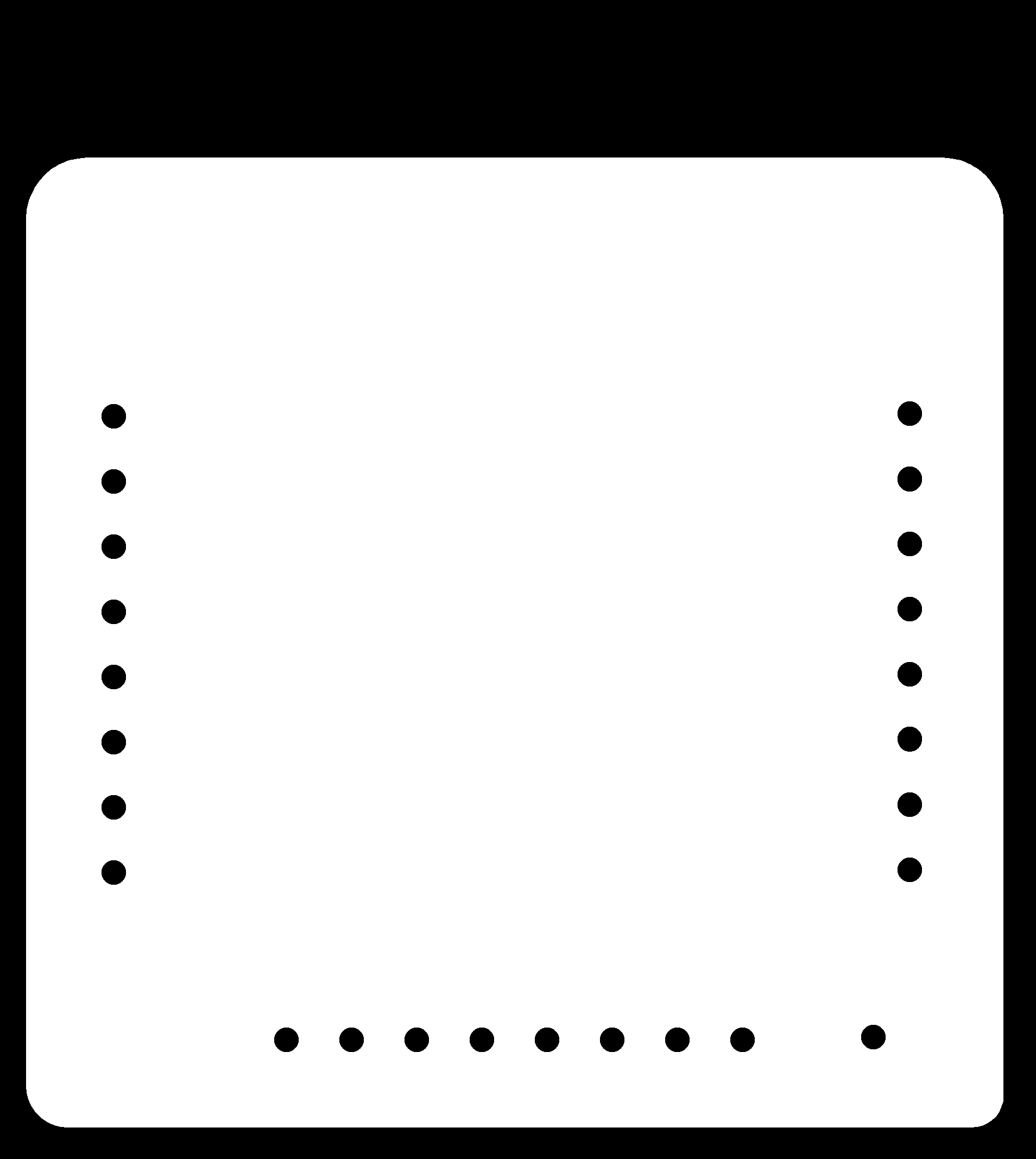
Mod Fabduino Mk2 schematic
I present the Mod Fabduino Mk2. Entirely based off the FabKit I/O, but cleaned up to make it immediately millable on the Modela using the 1/64th endmill without a change in the default settings. I also added a power indicator LED as those are always useful for debugging. Find the traces, exterior, board, and schematic files at the preceding links.
Programming, pins works and AVRdude seems happy
After many hours of milling, remilling, removing extraneous copper (We only had double sided copper PCBs, which would short the through hole pins), I had stuffed my new fabduino board to the point where it was programmable. I used Nadya's guide for getting a fabbed Atmega328 board into the Arduino universe. Happily, AVRdude was reporting the presence of a Atmega328, meaning nothing was majorly wrong with the circuit. I ran Nadya's bootloader script, and hoped for the best...
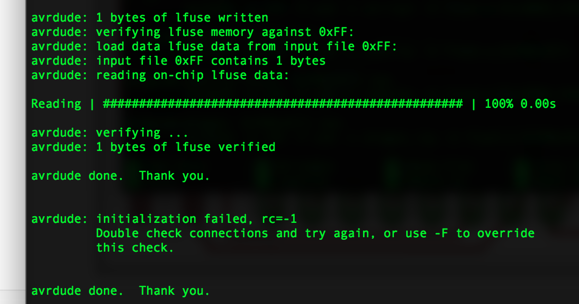
SNAFU! The board disappears after the fuses have been programmed
The fuses programmed successfully, and then poof, the board was gone. I probed and resoldered all the ISP connector pins multiple times, but nothing I could do could coax AVRdude to talk to my chip. Dejected at 2am, I decided to sleep on it.
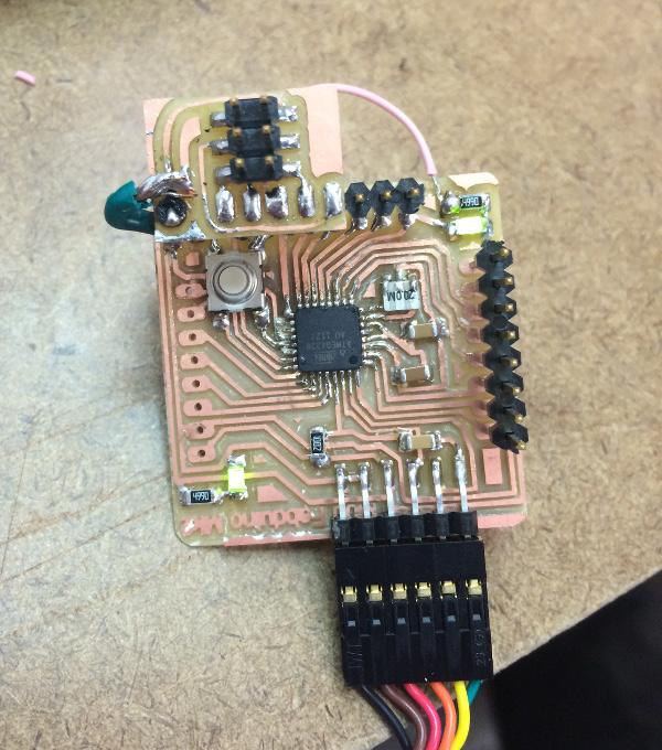
Test setup: Measuring the rails with a multimeter
The next morning, I tried to give some thought to why a board would program fuses successfully, but fail to communicate after that point. After googling "debricking AVR" and other similar terms, I came across this resource. Based on the information I found, it was clear that a failure to get an clock signal from the external resonator would lead to what I saw. I went back into the lab, resoldered all the pins associated with the resonator, and happily the board talked to the Avrdude again and I was able to flash the bootloader hex. After that point, the board could be successfully programmed over serial through the Arduino IDE. Shown above is the blinking LED from my "hello world" script, on the top right. A bit of a trap: I was using the "Arduino Uno" board setting in the Arduino IDE to program my board. The Arduino Uno actually has a 16Mhz oscillator, compared to the 20Mhz oscillator found in the lab inventory that I used. Since the compiler was expecting a 16Mhz clock, the timing was subtly messed up. When I tried to use the serial port, I just got garbled information. Again, thanks to Nadya's excellent tutorial, I knew at this point I needed to append the "fabduino" board to the Arduino IDE boards.txt file. In my case (Mac OS X, Arduino 1.5.8) I found the boards.txt file in Application->Arduino(right click the icon and select show package contents)->Contents->Java->hardware->arduino->avr->boards.txt .
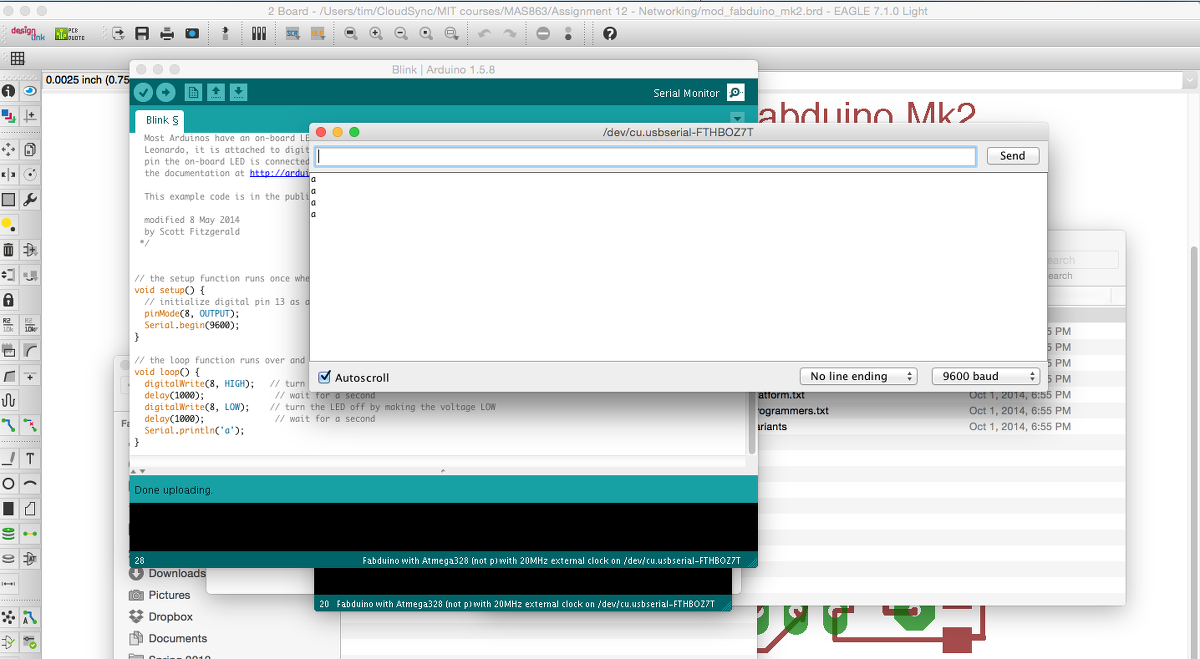
Printing 'a' across the serial port. A monumental achievement
With the boards.txt situation sorted out, the serial port on the board actually worked. Never had I been so happy to see the letter "a" show up.
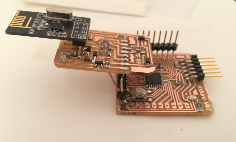
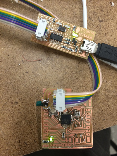
Board inception
I then desoldered the ISP programming breakout using the solder sucker, soldered the nRF24L01 breakout (which I dubbed the TF RF), stuck the nRF24L01 module into that, and then installed the RF24 Arduino library from Github into my Arduino libraries folder, and fired up the included library examples. Briefly, it seemed like configuration data could be read from the nRF24L01, but the transmitting failed with the informative "failed" message. Perhaps a few pins weren't properly connected or level shifted? Regardless, I was pretty happy with my 3D board setup, which is kind of cute but also satisfying in its completion.