
Before arriving at MIT I worked at the NASA Ames Research Center where I helped developed a robotic assembly system for the construction of digital cellular materials. The system utilized a 5-axis gantry system from Shopbot with a custom end effector fitted. The system is currently capable of building blocks of 3x3x3 units, fixing parts together with 0-80 nuts and bolts. A limitation of this system is that it can only build something as big as itself. Therefore, our group at NASA and in the Center for Bits and Atoms have been working on relative robots. In this case that means small robots capable of traversing across and through the structure to carry out assembly and inspection tasks.
For my final project in this class I'd like to design my own relative robot capable of sensing broken or unconnected voxels within the structure. This is a fairly big task, therefore I've broken it down into three sections that I'll work through as time permits:
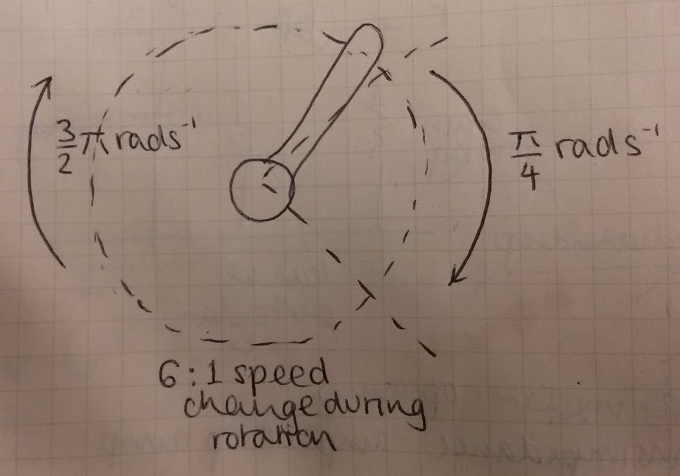
An inital design consists of legs running at a non-uniform angular velocity. Each 'leg' must travel at 0.25*pi rad/s for a quarter of a turn and 1.5*pi rad/s for the the remaining 3/4 of the turn. This can be acheived in number of ways, two routes of investigation are electrical speed control and a purely mechanical design. Below are some ideas and resources I'm looking out to figure ou hoow to vary rotational speed.
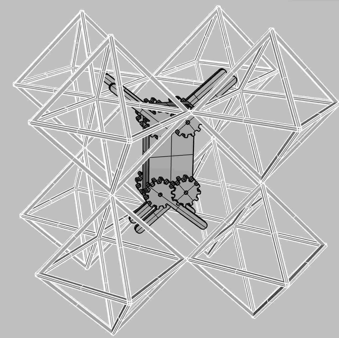
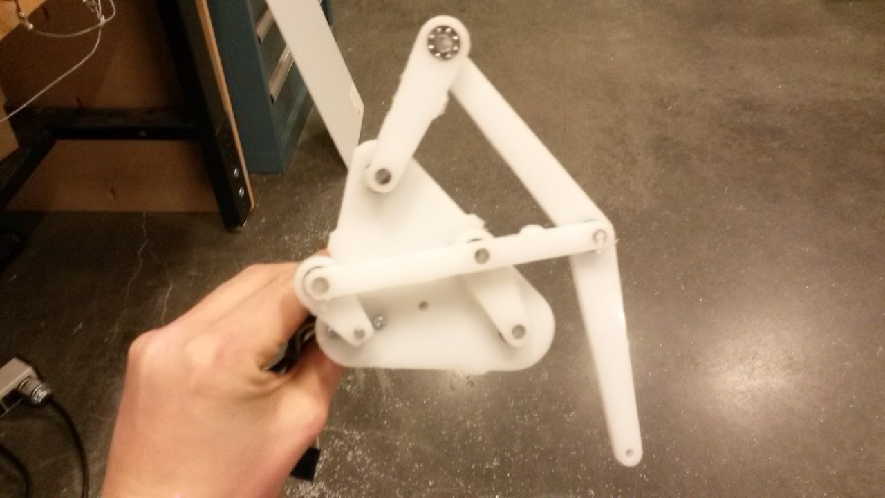
I tried modelling these degrees of freedom in operation together and clearly this configuration is not physically possible. I still like the idea of using continuous rotation to drive the robot through the structure.
I got inspiration from this YouTube video for the basic mechanism. I'd plan to make a robot with 4 or 6 feet that can traverse the surface of a voxel structure.
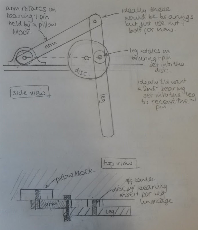
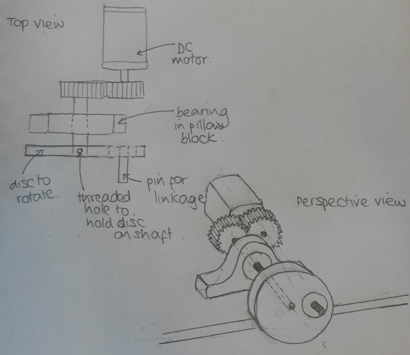
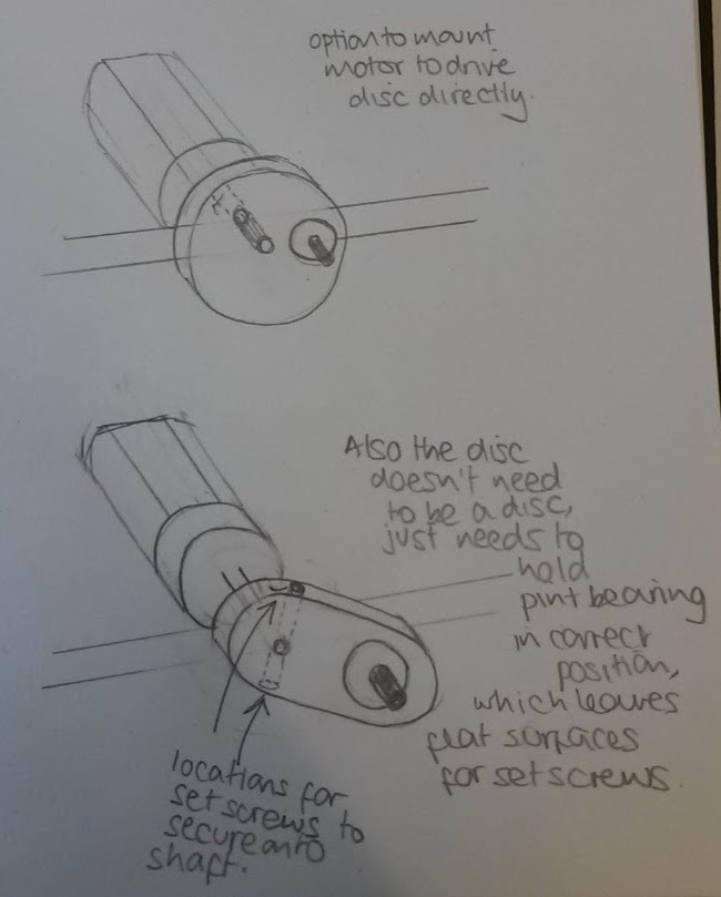
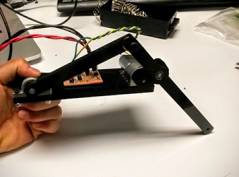
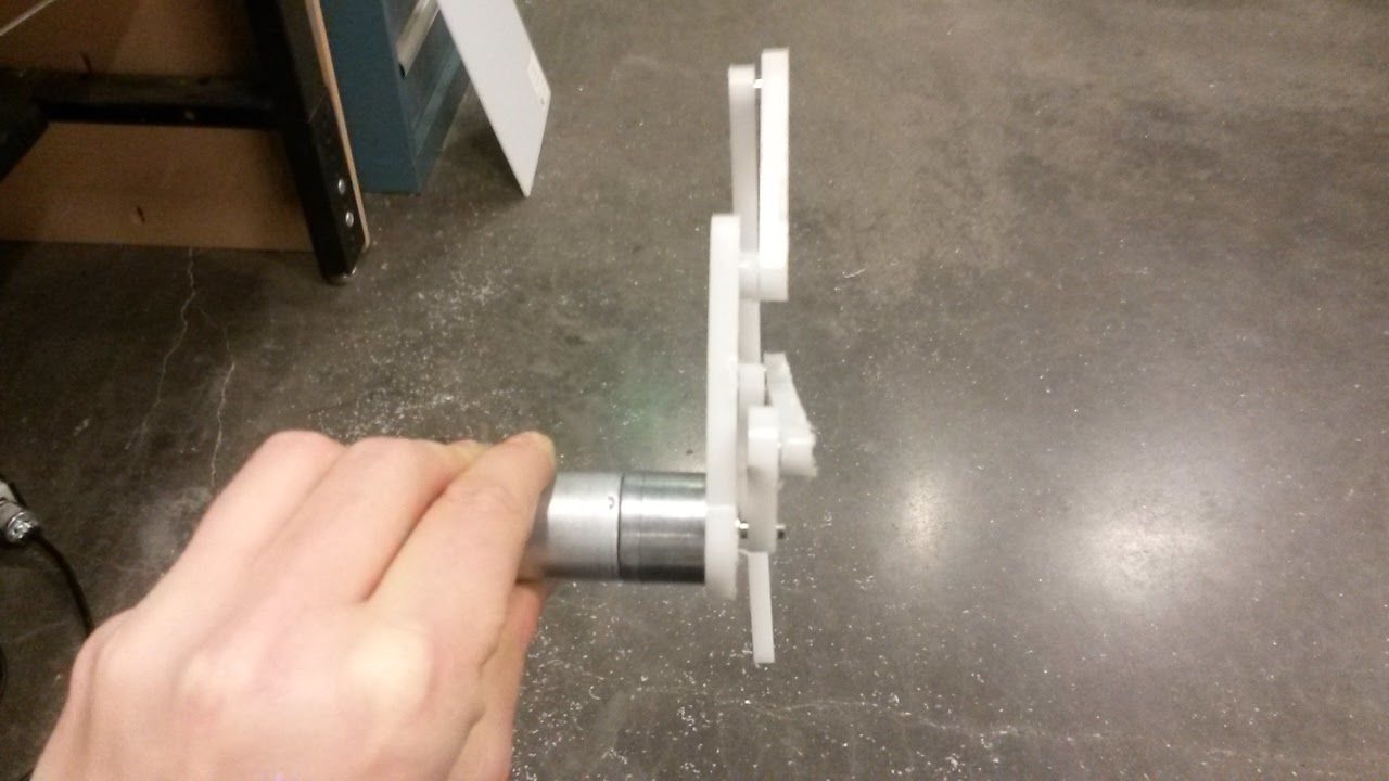
Initally I'm looking at using DC motors to drive the disks, below are some sketches for the configuration of the drive train, created with the help of Benjamin and Sam .
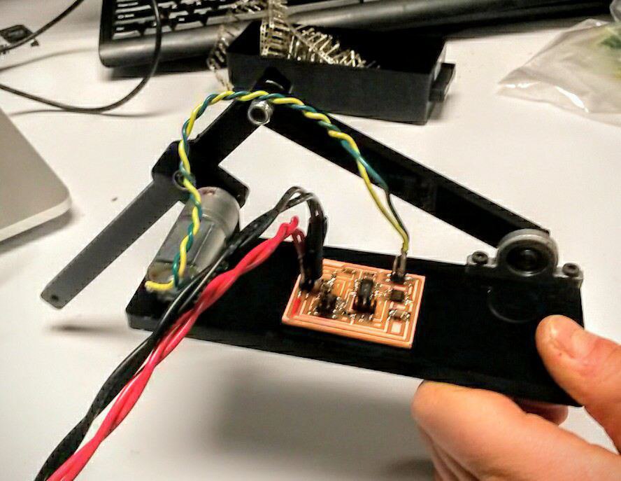
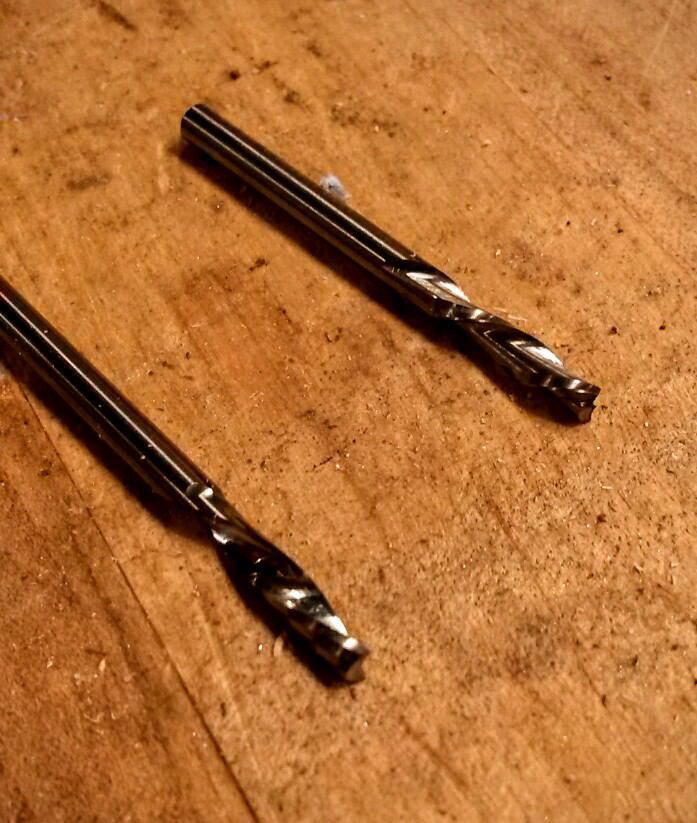
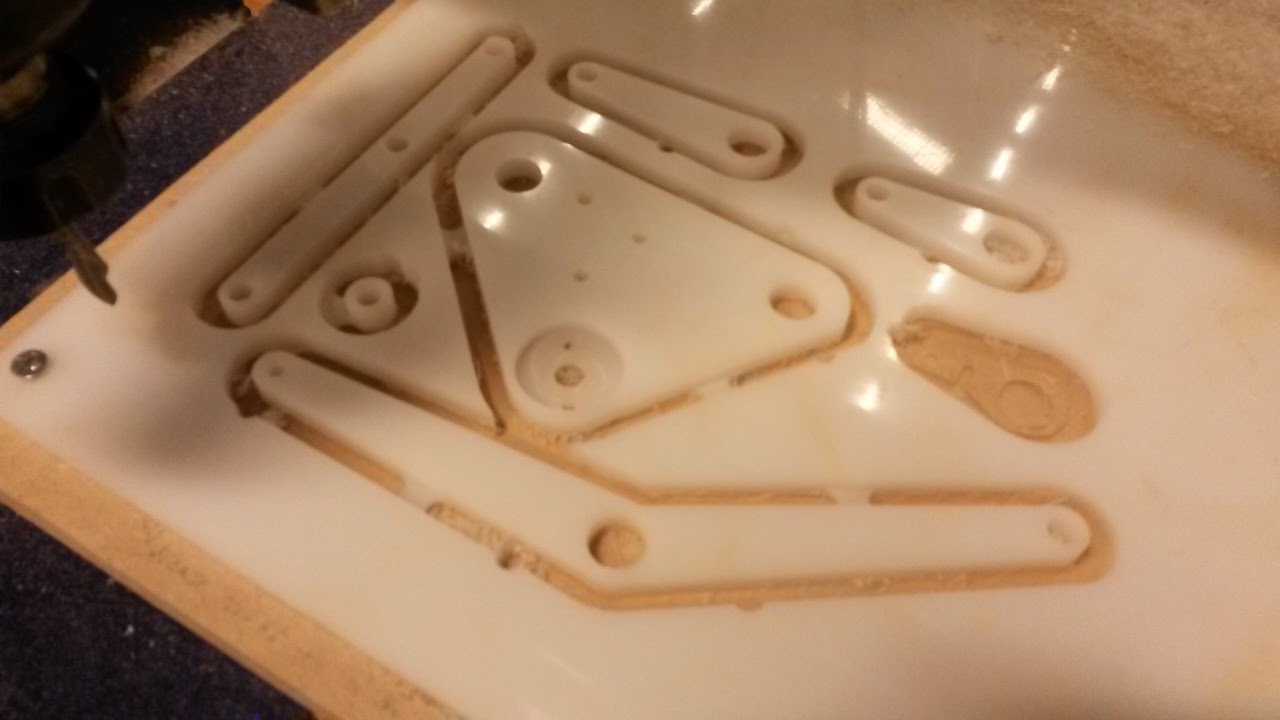
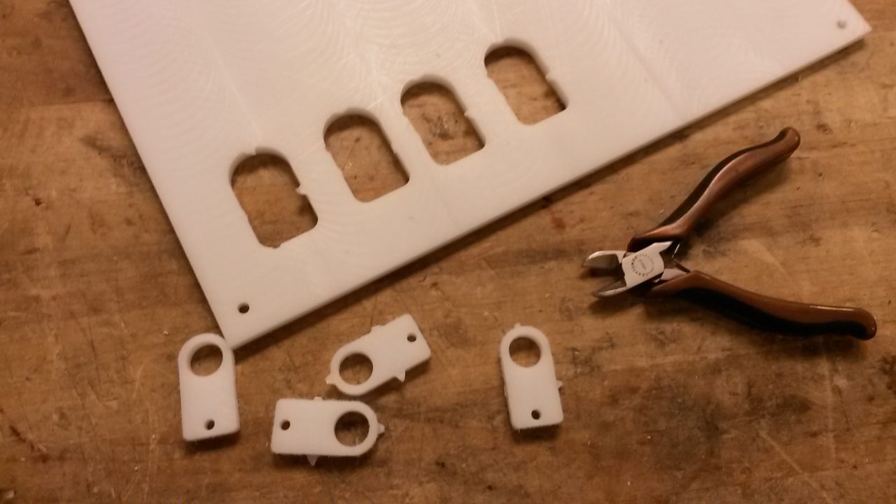
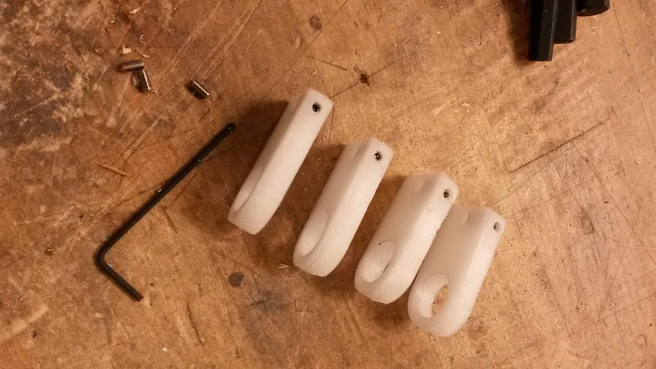
I ordered all the parts I needed, milled the linakages and body from Delrin on the Desktop Shopbot. I ended up using a single flute endmill with a scalloped cutted edge as the Delrin swarf welded to the 2 flute square end endmill.
Feedback was that it is good to limit the number of controls to the number of degrees. Therefore, given that this robot will initially have a single degree of freedom in terms of a single locomoting direction, then it might be wise to create a design where all the legs are driven by the same mechanism. The controller could then only need to send a single signal.
Shopbot machining - Learned how to use the ramping and tab functionality within the Shopbot software. I was using the Super-O 1/8" end mill and broke it with the following settings - 12,000rpm, 30 ipm feed rate and 15 ipm plunge rate. I wasn't using ramp settings at this point so that may well have contributed to the breakage.
I had some trouble getting the motors moving. I used Neil's code as a starting point however (with Sam's help) realised I needed to increase the on and off time in equal proportion to give the motors a chance to recognise the PWM power. So rather than on for 3 micro seconds and off for 1 micro seconds I set it on for 30 microseconds and off for 10 microseconds.
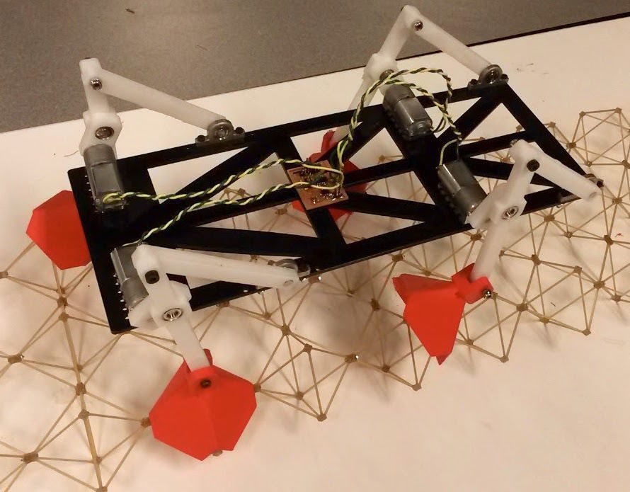
In addition, the h-bridge limits current to 2A, on average four motors seemed to be using 1.2A, which means that the peak current would have been exceeding 2A. To overcome this issue I added a 47uF capacitor and used a board I had made previously which includes 2 hbridge chips. Once I did that, I have the robot walking/shuffling with all four feet.
This is the c file for my double h-bridge circuit, and this is the make file.
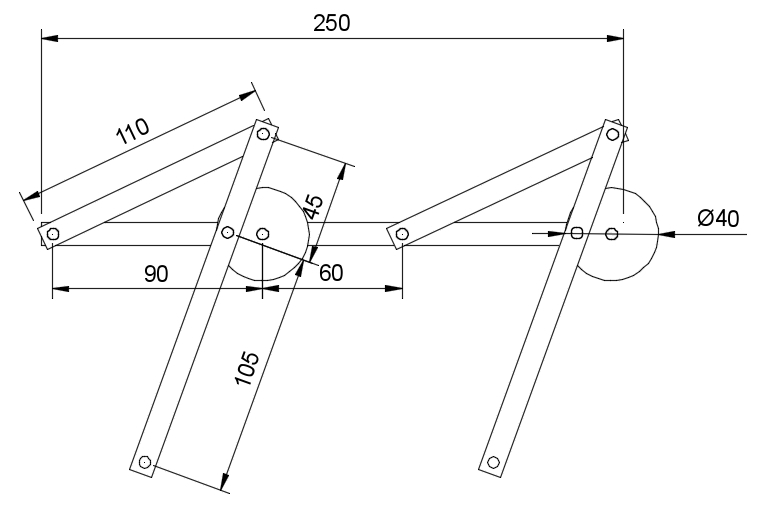
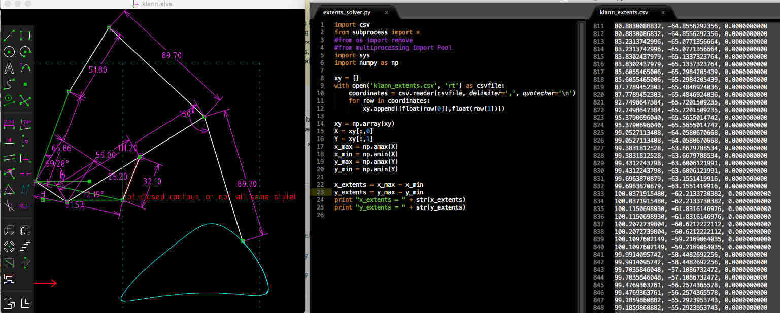
I developed a new linkage after looking through a range of possibilities on this Wikipedia page. I modelled the new linkage in Fusion again, however I was keen to size the linkages properly for the new design. Ideally, I need the change in y of the motion to exceed the height of half a voxel pitch and the change in x to equal a whole voxel pitch. This results in dy = 38.1mm and dx = 76.2mm. I tried the following methods with some success:
Working through these pieces of software makes me want to design my own linkage design software.
Milled new linkages from HDPE which cut a lot more easily that Delrin.
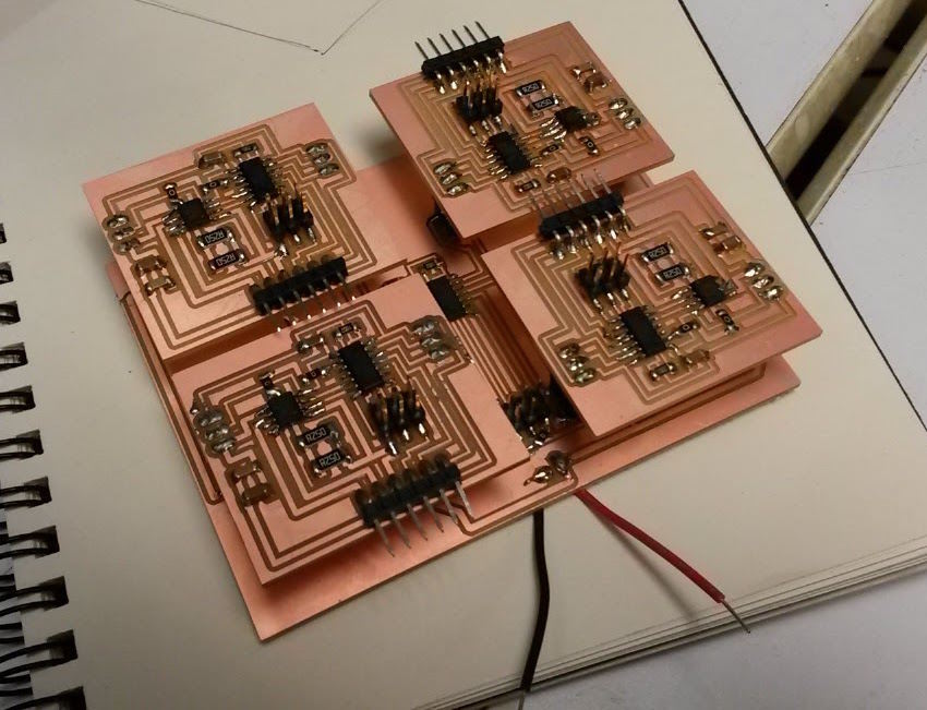
I've designed a new DC motor controller board which has feedback for encoders and current sensing, I intend to fabricate 3 more and mount them on a master controller board. The slave boards will run a program where they listen for instructions from the main board. Each board needs to carry out the following 3 time critcal functions:
The first step was to get the boards operating separately, in order to do this I milled the Master board to route two voltage levels and GND to each board. This was successful for all four boards until I tried reprogramming one of them whilst the motor was connected. I think this caused the voltage regulator on the master board to burn out, so perhaps it caused excess power to be drawn to change direction??
There were a number of issues with this design:
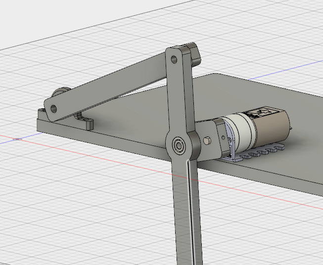
I machined new drive linkages from Delrin which took set screws a lot more successfully and no longer slipped when attached to the DC motors. When driven continuously, the front and back legs end up moving in unison. I should be able to generate a reasonable gait by pairing diagonally opposite legs to move simultaneously whilst the other pair remains still.
Didn't exactly get the locomotion I was after. They look like they're having a good time though.
| Component | Source | Cost |
|---|---|---|
| 12"x12" 1/4" HDPE | US Plastics | $27.79 |
| 12"x12" 3/32" Delrin | US Plastics | $8.59 |
| 4 x 25L DC Motors with encoders | Pololu | $139.80 |
| 4 x 3D printed feet | Sindoh 3D Wox | $10.00 |
| 4 x Aluminium brackets | McMaster | $6.00 |
| 24 x Bearings (OD = 0.375", ID=0.25", thickness=3/16" | Amazon | $40.00 |
| Circuit boards (including 4 H-Bridges, 5 Attiny44's and assortment of small components | Digikey | $20.00 |
In order to get data from the encoders I wanted a means through which to actually see what was bring read. I chose to use the SoftwareSerial library in the Arduino IDE. To avoid having to remake the boards with a dedicated FTDI connector, I repurposed the used 1 of the ISP pins as Rx using SoftwareSerial. I then program the Tiny's using an AVRISP, then remove the connector and use 2 jumper wires to connect an FTDI cable to the Rx pin and GND. I used the following code and correct 2 key mistakes to get it working. 1) Burn the bootloader to ensure the chip is running at the correct speed. Before I remembered to do this the characters that I was sending were being displayed as question marks in little black diamonds i.e. gobbledigook. 2) Ensure you're sending a char to the serial port. This website was quite helpful.
Using the code below I managed to read out the encoder position. I'm using these motors which have integrated 48 CPR quadrature encoders on the motor shaft, providing 4741.44 counts per revolution of the gearbox’s output shaft. I put the encoder counter loop in the main loop where I generate the PWN signal. However, printing to the Serial port seems to slow down the motion. So I tried to get the counter loop running through a Pin Change Interrupt. This article describes Pin Change Interrupts, I used the ATTiny44 datasheet to figure out how I should set the registers. The problem is that when you try and run the SoftwareSerial library at the same time as the avr/interrupt library you get errors as they're both trying to use the same Pin Change Interrupt. I probably could have gone into the SoftwareSerial library to change this but decided to only use one of the other at one time.
So far gotten Pin Change Inturrupts to work. Next step, replace the master ATTiny because I think I bricked it measuring voltages. Use that to send commands to the front and rear set of legs. Send a go command the each set of legs and trigger the next set of legs when it's recieved an "I'm done signal" based on when the leg has reached the required set of encoder ticks.