Home
Project 3 - Electronics Production
This week, I learned how to mill a printed circuit board (PCB), populate it with itty-bitty components, and program it to become a programmer.! I knew nothing about the process before we started, and it blows my mind that we created the thing that will program other things!
EDIT: I understood the process of making the FabISP, but didn't fully understand what each component did, so I went back to what we did this week and learned in more detail how exactly the FabISP works using this tutorial.
Goals
Class Assignment:
- Group Assignment: characterize the specifications of your PCB production process
- Individual Assignment: make an in-circuit programmer by milling the PCB
My Personal Goals:
- Make the board, and make sure it works
- Understand what the components do
Things I learned

- How to mill a PCB board
Later, when I got curious/things got annoying:
- Pull up/down resistors
- Decoupling Capacitors
- Transistor-transistor Logic Levels
- Shift Registors
- Diodes
- Voltage Clipper Circuits
- Differential Signals - particularly design rules
The Process + Pics
- Getting the specifications
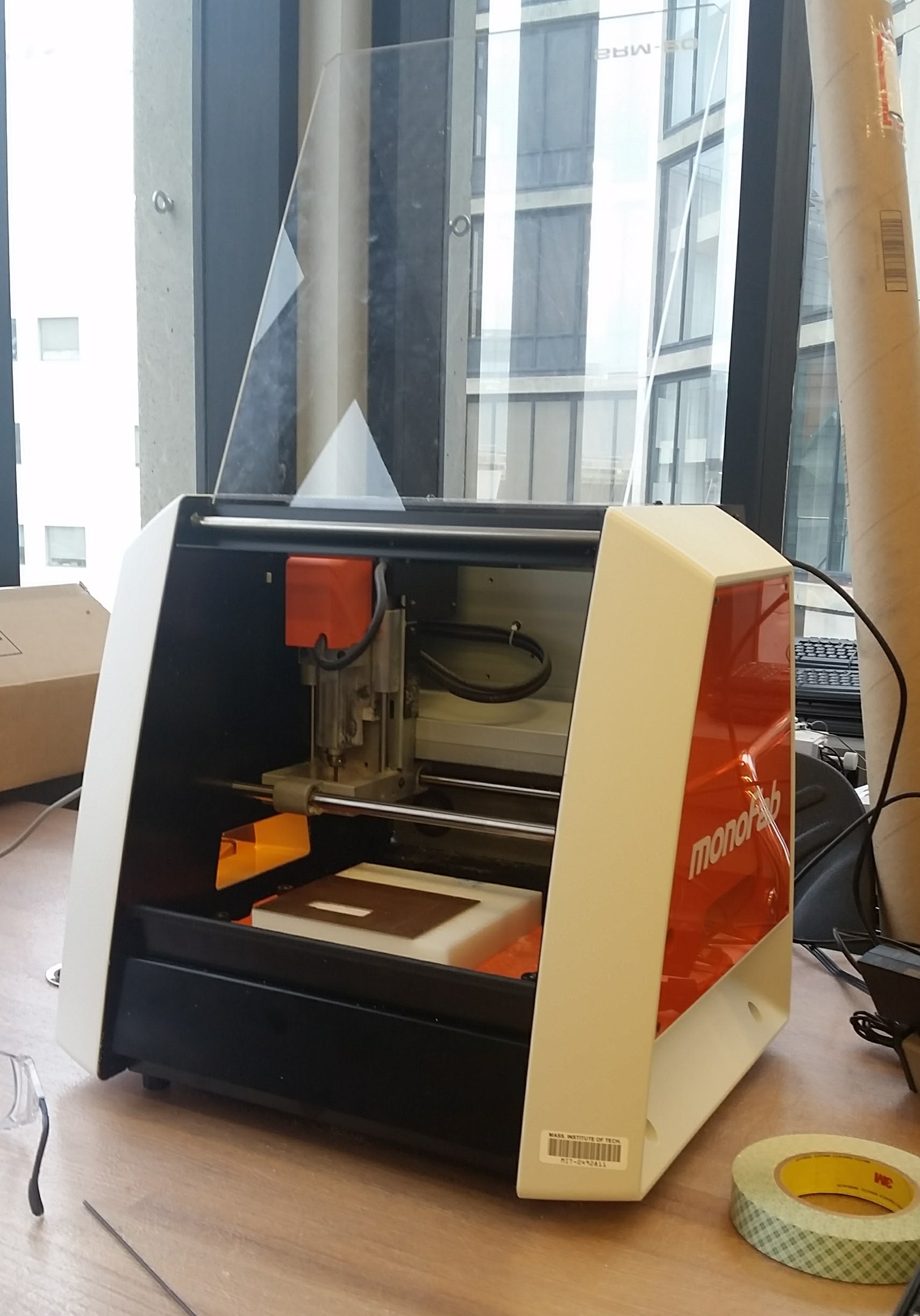
The EDS shop uses a Roland SRM-20 tabletop CNC milling machine, which has a cutting volume of 8" x 6" x 2.38" (pictured to the right).
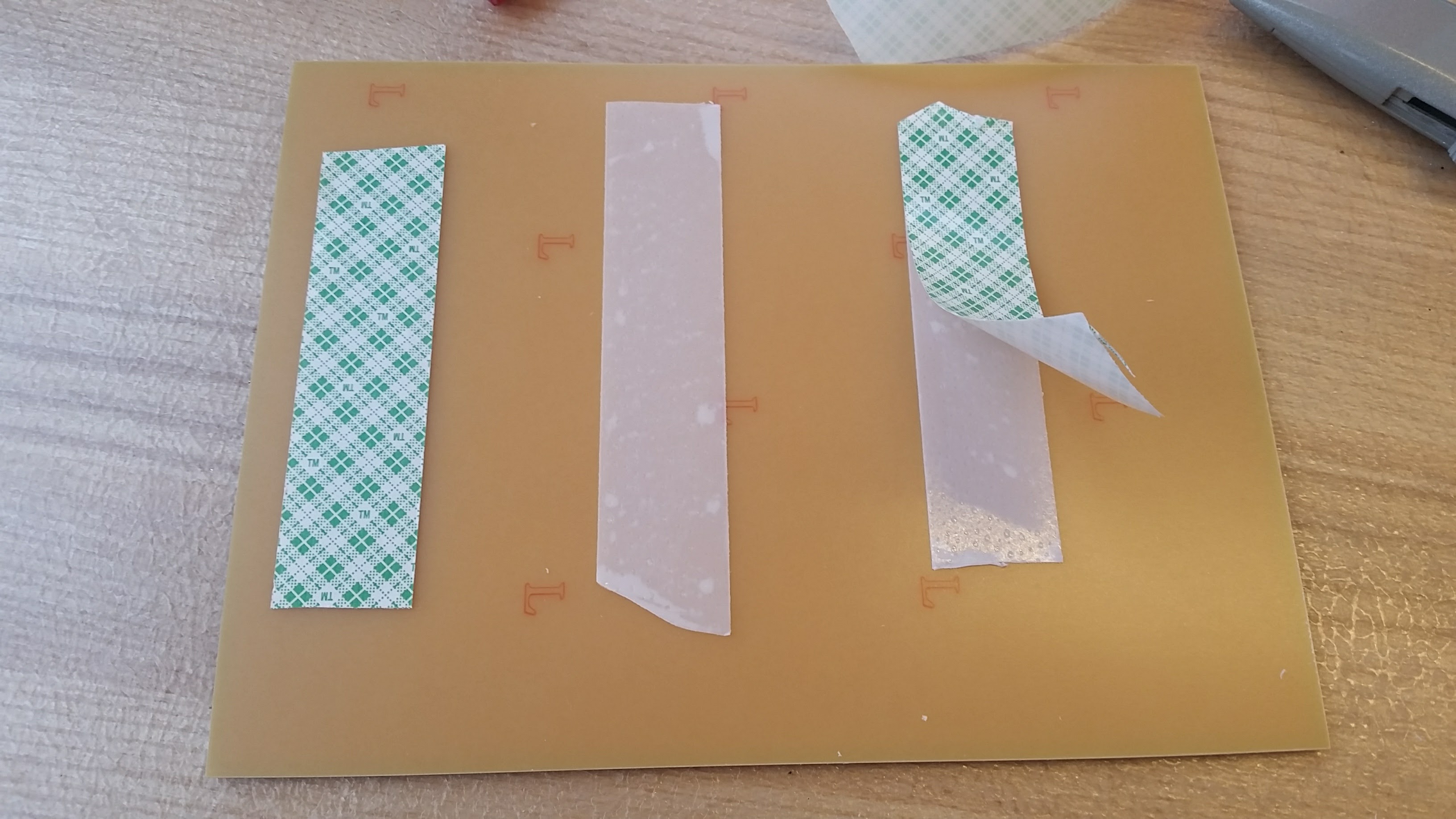
 To attach the copper plate onto the platform of the machine, we simply used some double sided tape.
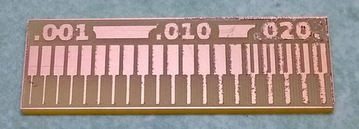
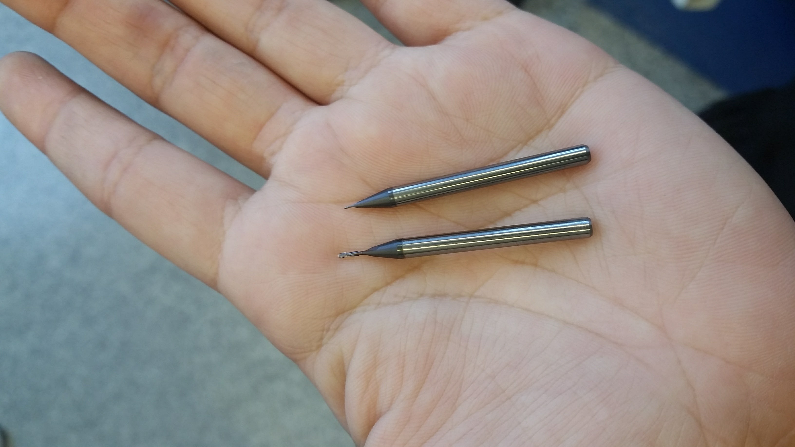
 During our training, we learned how to set up both tracing designs and cutting out the board. While cutting, we had a problem as the endmill came loose towards the end, leaving the PCB jagged. As a group, we also characterized the milling process using the line pattern that Neil showed us in class. We used the 1/64th endmill, which is the same as what we will be using to etch the traces of our circuit.
The pattern goes from .001" to .020". The thinner traces look cleaner than the thicker ones, but anything less than .0156 inches doesn't get etched. This makes sense, because the region has a width that is thinner than the 1/64th inch tool diameter, and so the MODs software does not trace it; otherwise it would remove material that it shouldn't.
During our training, we learned how to set up both tracing designs and cutting out the board. While cutting, we had a problem as the endmill came loose towards the end, leaving the PCB jagged. As a group, we also characterized the milling process using the line pattern that Neil showed us in class. We used the 1/64th endmill, which is the same as what we will be using to etch the traces of our circuit.
The pattern goes from .001" to .020". The thinner traces look cleaner than the thicker ones, but anything less than .0156 inches doesn't get etched. This makes sense, because the region has a width that is thinner than the 1/64th inch tool diameter, and so the MODs software does not trace it; otherwise it would remove material that it shouldn't.
- Milling the PCB
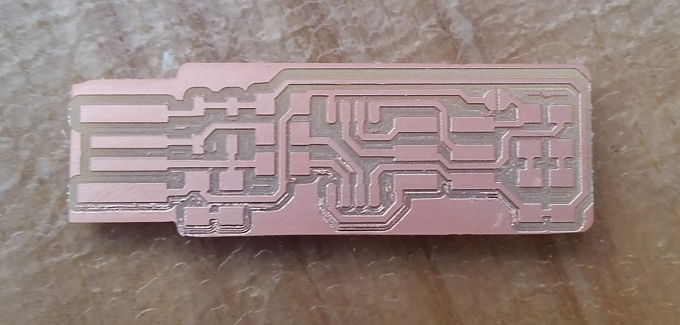
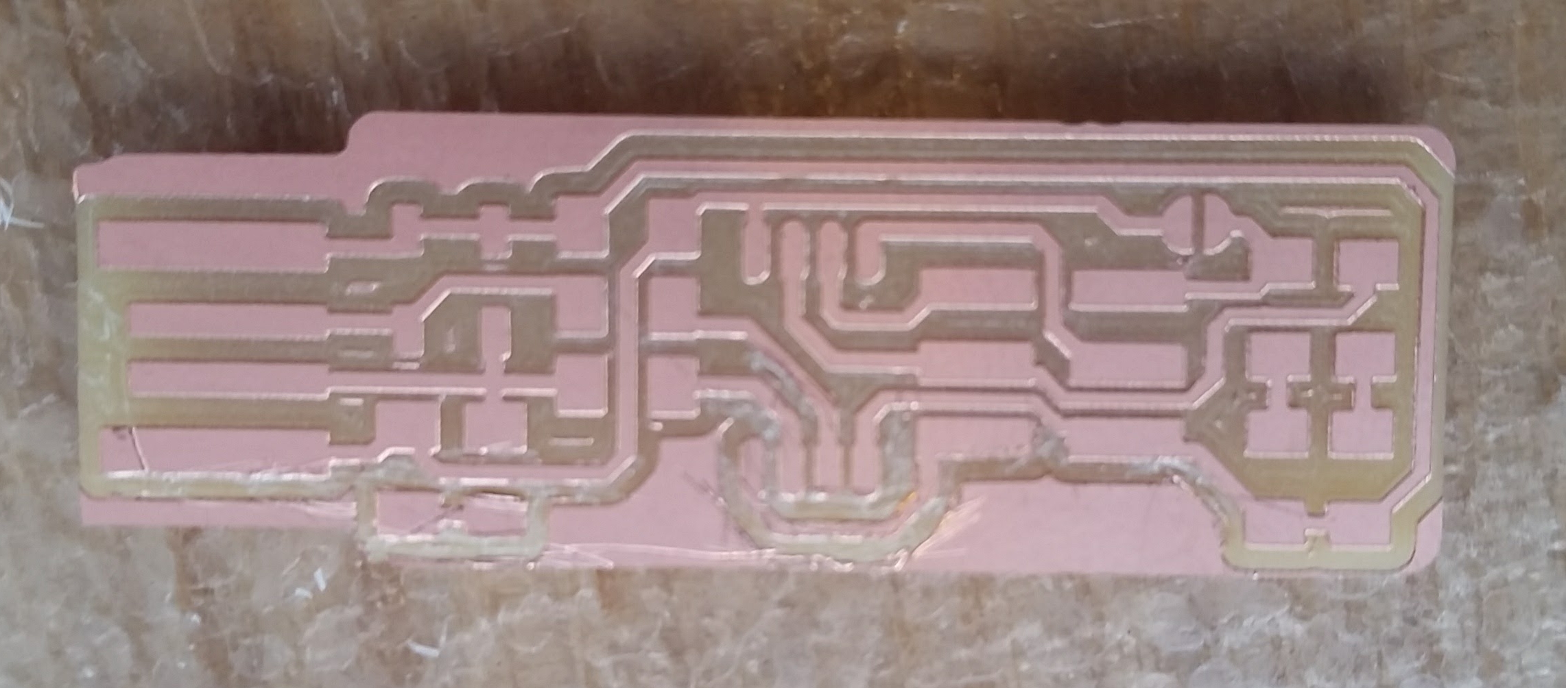
To create this USB-lookalike PCB, I used the CNC milling machine to etch in a circuit onto a copper plate, and then cut it out. I manually set the endmill to the copper surface, and the MODs software calculated the vector files for both processes, taking into account the endmill sizes (1/64th" for tracing and 1/32nd" for cutting.
 Unfortunately, the first time I milled the board, the copper plate was slightly uneven on the platform, and so some of the copper wasn't etched all the way. This could have created a short circuit, so I did some surgery by hand to engrave out the unfinished copper paths. I also had to carve out a little copper rectangle at the tip of the PCB to ensure that the voltage and ground never touch. Overall, the millilng process is simple, but the results are impressive, even with some parts done by hand (in my opinion, it adds character).
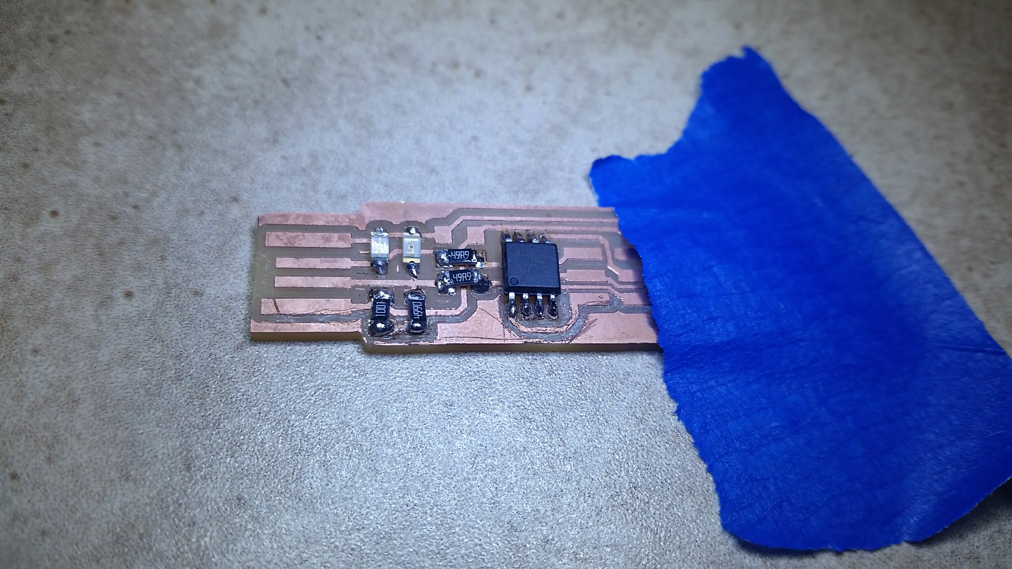
- Soldering the board
After the PCB was printed, I utilized this guide and got ready to populate it with the following components:
- 1x ATtiny45 or ATtiny85
- 2x 1kΩ resistors
- 2x 499Ω resistors
- 2x 49Ω resistors
- 2x 3.3v zener diodes
- 1x red LED
- 1x green LED
- 1x 100nF capacitor
- 1x 2x3 pin header
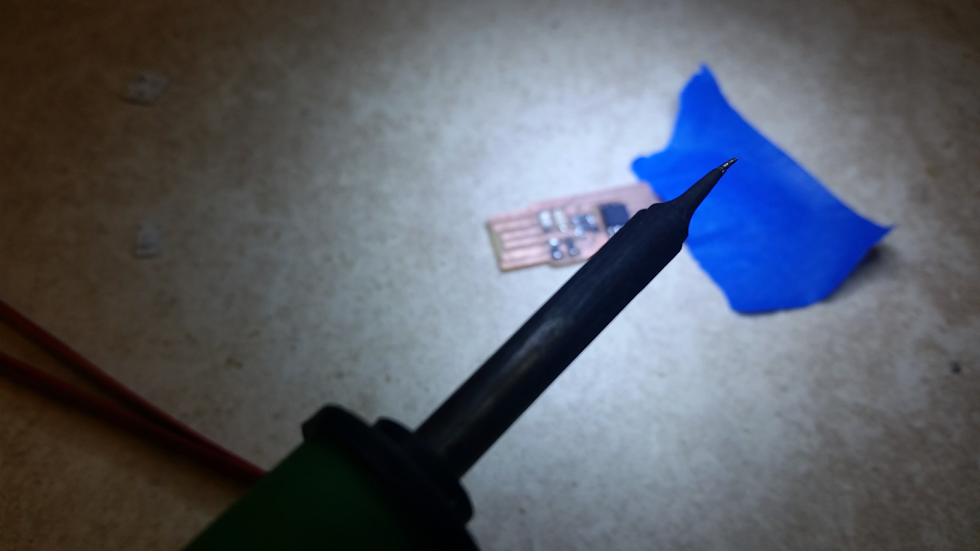
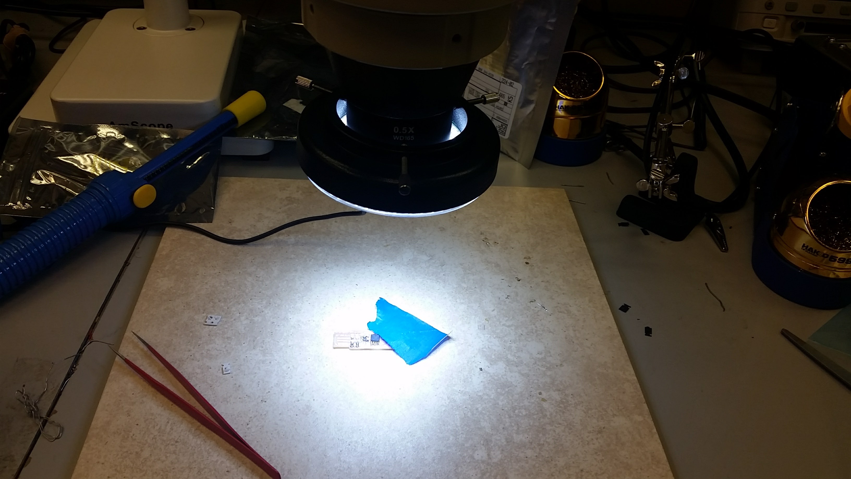
I taped down my circuit board and used the smallest soldering tip I could find. This worked decently, but then I discovered an amzing thing device that made everything so much easier - the micropscope! It didn't take long to get this new hand-eye coordination down, and using a the magnifier to look at what I was doing made my soldering cleaner and more efficient.
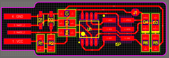
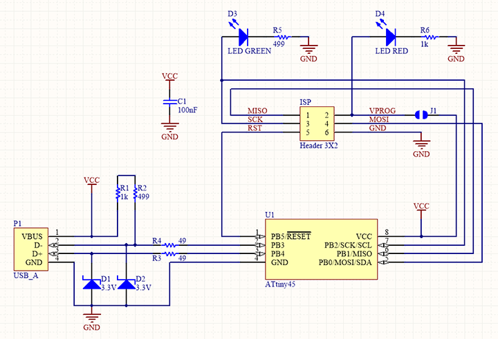
These are the schematics I followed as reference for where each of the parts should be placed.
I really like doing delicate work with my hands, and liked the methodical work. Although I wouldn't want to do this all the time, I enjoyed making the board, improved with each component I added, and can't wait to make more!
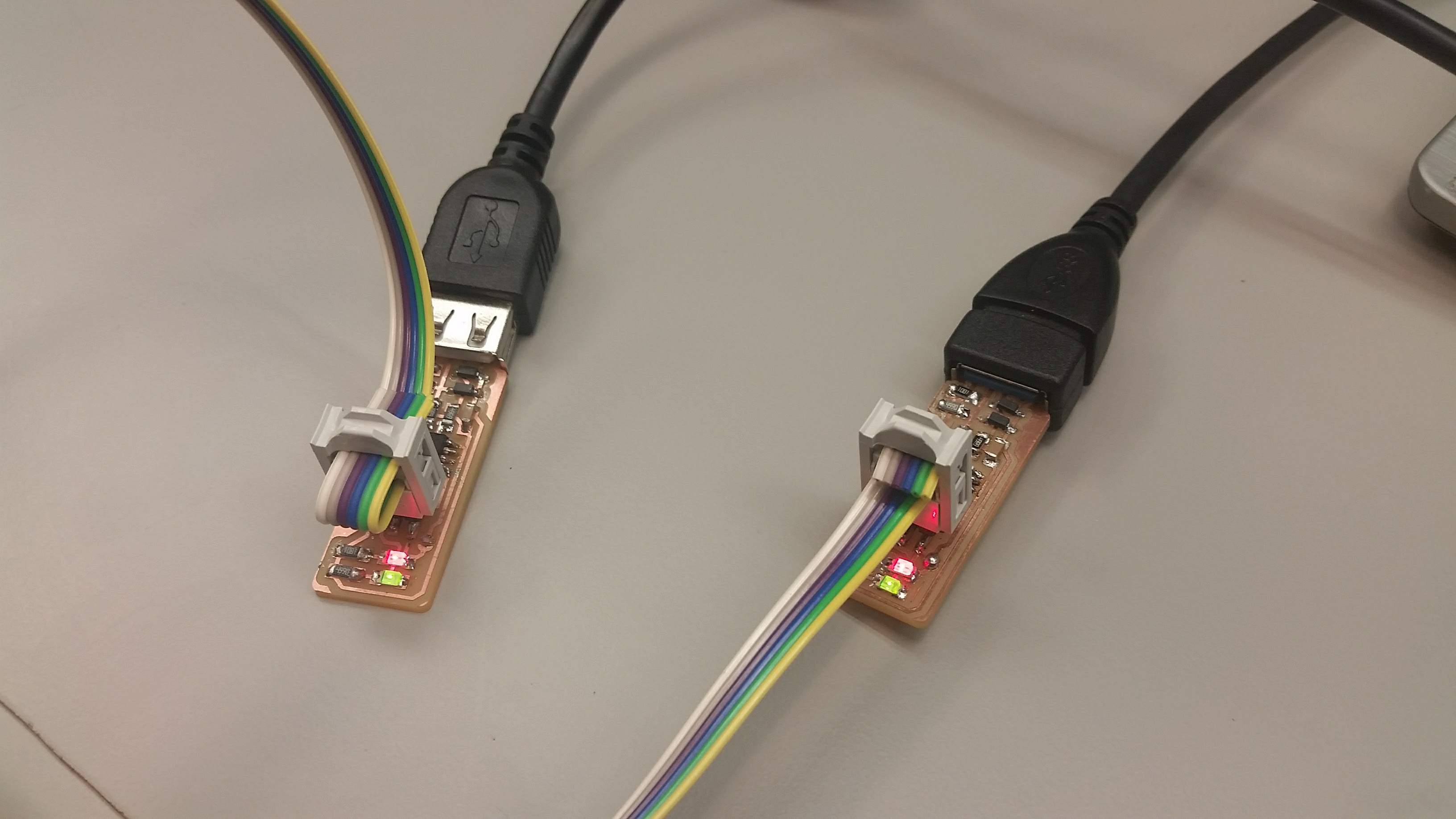
Here's what the finished FabISP looks like!
- Programming the ATtiny45
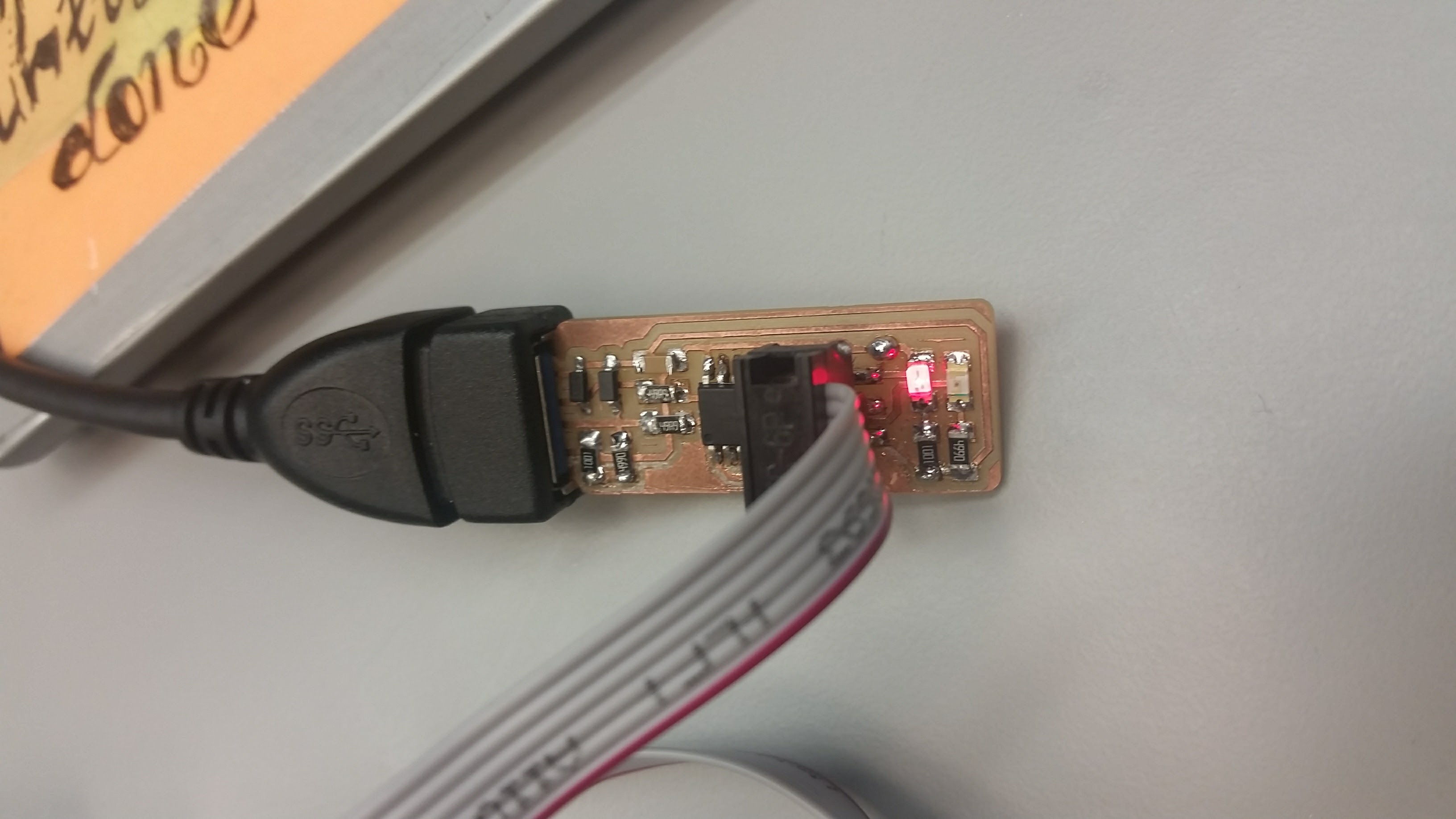
My classmate Alexandre was a huge help for this part, especially for fixing errors that weren't covered in the guide. I just switched over to using Linux more (I had it before, but alternated frequently between Windows and Linux), and getting things set up has been taking some time. First off, I found it really interesting that we needed to make a jumper to connect Vvv to the Vprog pin on the ISP header so that we could program the tiny45, and then would later remove that solder bridge. The whole concept of programming a thing to program other things is pretty neat (EDIT: I am still blown every time I program a board that I'm using something I made to do it). Anyway, before programming it, I double checked all my connections and dowloaded the firmware on the Linux partition of my laptop. I hooked up my device to my laptop, and the little red light that meant it was able to be powered (I didn't mess up the printing/soldering!!) was the best sight I'd seen that day!
 I initially tried to program it using the given programming unit, but the make flash command didnt work on the first few tries, so instead I decided to program it with a labmate's finished programmer. We hooked up my to-be-programmer to his programmer and to my laptop, ran make flash, make fuses, lsusb, and make rstdisbl. Then, I disconnected the Vcc to Vprog pin jumper, and voila! I was done!