week 9: machine design
This week's assignment was a group project. In our section, we had to build a machine complete with integrated subsystems. Our joint project page is here. Even though I spent a ridiculous number of hours working on this project, it was nice to work together as a section and get to know the other EECS students.
Our group met on Thursday and decided that we would stray from copying Jake's machine and instead build a delta picker. We organized ourselves into five teams: design/CAD, frame manufacturing, arms/joints, end effector, and programming/control logic. I was in the arms/joints team, along with Natalie and Alex Kaspar. However, in the end, I feel like only about 20% of the work I did on this project was for the arms/joints.
EDS was closed on Friday and Saturday, so we met on Sunday to begin. The design team had developed CAD files After a discussion together to clarify some design questions, we split into our teams. Alex, Natalie, and I got together and started planning for the arms. The overall design team had settled on a delta picker design with three linear rails, and based on that, we decided we needed two arms to connect to each rail, for a total of six arms.
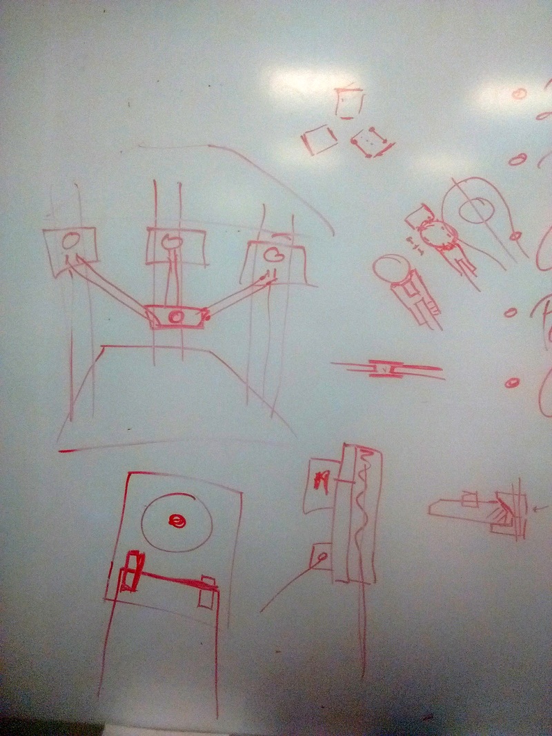
Arm/joint brainstorming.
We also came to the conclusion that the arms needed to be rigid in order for our end effector plate to remain level when moved. However, we needed joints for the arms that allow the arms to move in any direction. We started researching universal joints and ball and socket joints, and used one of the 3D printers in EDS to print some test files for potential joints from Thingiverse/Instructables.
- Universal Joint from Thingiverse
- Ball and Socket Joint from Thingiverse
- Modular Ball and Socket Joint from Instructables
We printed all three. The universal joint didn't work at all, because the pieces were completely stuck together. The second one kind of worked, but not well. The third one worked, but the 3D printing left an uneven, ridged finish on the surfaces, which prevented the joint from rotating smoothly.
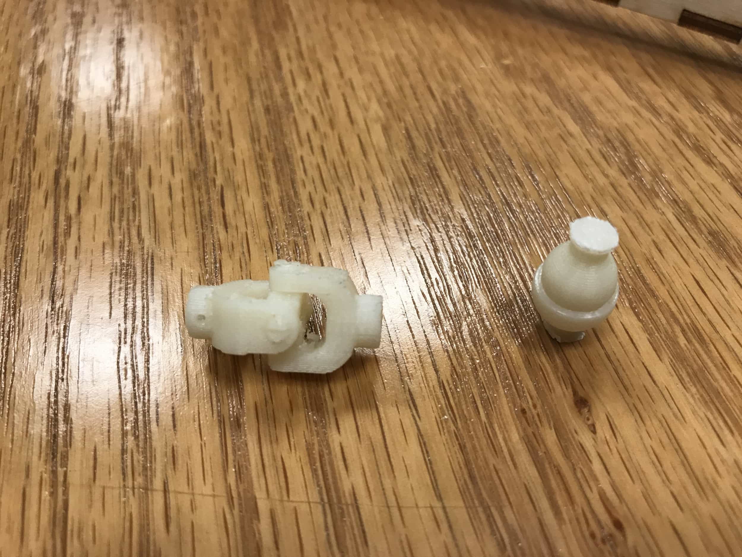
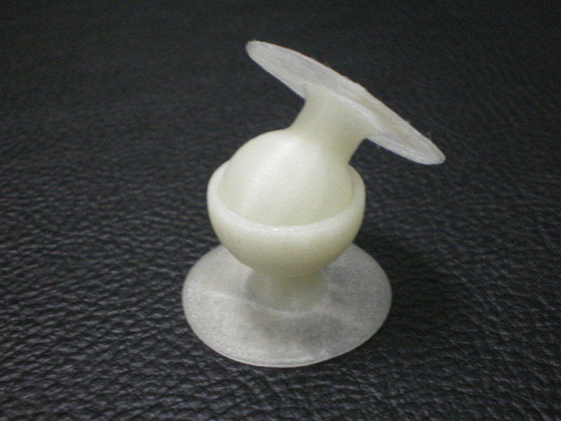
Our 3D printed test joints. None were very successful.
We changed up our idea for the arms to one that was simpler. Instead of requiring special joints, we could thread string through a hollow, rigid tube. We didn't have any rigid tubes, and figured we could fabricate our own. We thought we could laser cut something, although that meant we couldn't make the tubes round. Instead, we drew up CAD designs for a rectangular tube to be made from four cut pieces. We laser cut it out of acrylic, but had trouble getting the pieces to press fit correctly. The joints were too loose on our first attempts. We then accounted for kerf, and the fit was closer, but still loose. Then we increased the kerf, but then we couldn't join the pieces. We decided that acrylic might not be the best material, because it is so smooth, and switched to plywood. I had experimented with plywood press-fit joints a lot recently for a project for another class, and our connections worked on the first try. We created all of the arms like this. We weren't exactly certain what the length of the arms should be, because it was dependent on the frame manufacturing and control logic teams, so we cut them to be a length we knew we wouldn't need to exceed.
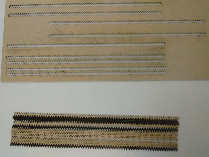
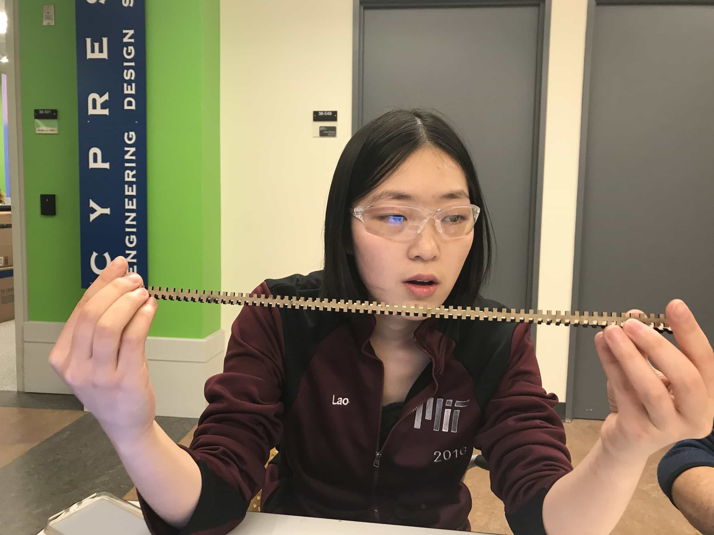
We struggled to cut with the acrylic.
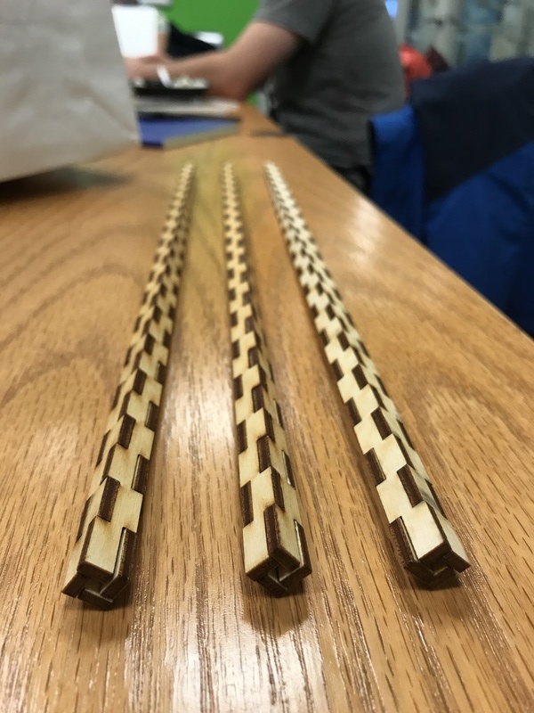
Our plywood arms.
On Sunday, I also provided help with CAD designing. We realized we had to adjust the base design because the three attachment points in the base needed to form an equilateral triangle, which they currently didn't. I helped Xin and Casey with Rhino to make the needed adjustments to the design which could be passed along to the manufacturing team. On Monday, the manufacturing team needed some STL files to be turned into 2D files from which they could create the toolpaths for machining, so I also helped with this. We also fed fishing wire through our arms (which is more difficult a task than it sounds). However, our parts were still being machined Monday, so there was a limit to what we could do. Because there were struggles with the machining process and that was the bottleneck in making our machine, we decided to laser cut the base plate and end effector. This also allowed us to increase the size of the base plate from the original design. We cut these parts from plywood.
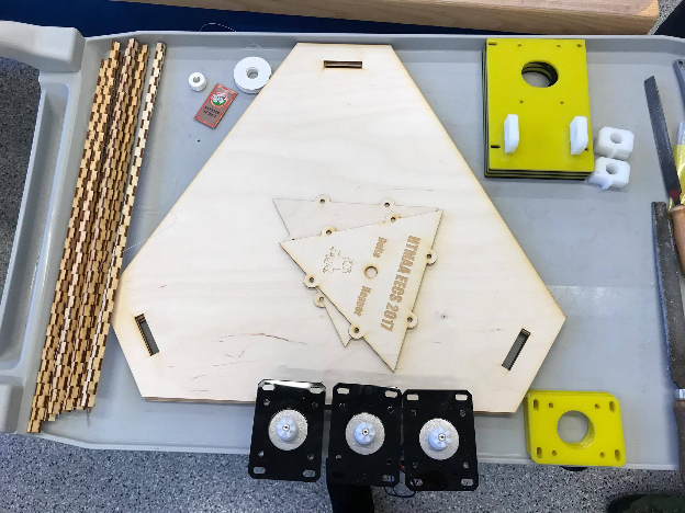
We laser cut the base adn other parts of our machine.
The frame manufacturing team had stayed late Monday night machining parts, so on Tuesday I arrived at EDS in the morning and some parts were cut. The rails hadn't cut cleanly though. I used an X-acto knife, along with a variety of other tools, to trim off the rails so that the pinion could travel along it. We ended up re-machining the rails because they were missing a chamfer, but I got really good at cleaning and smoothing the rails. I worked on sanding various parts to help them fit correctly.
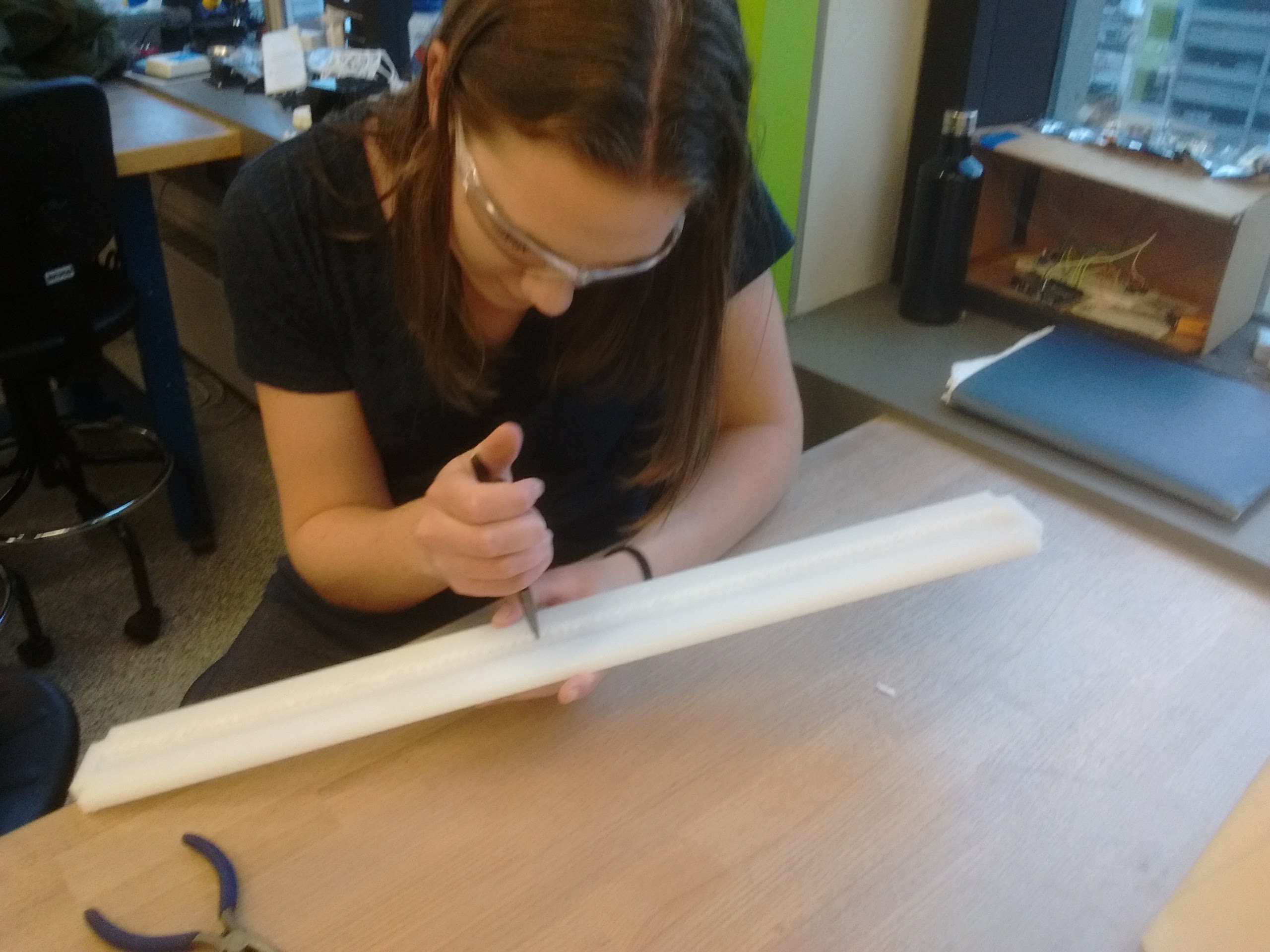
Me cleaning up the original rails we machined.
Later on Tuesday, I stopped by Alex Genshaft at the architecture shop to check on the machining, and brought back the machined slides for the rails to EDS. They needed post-processing, because the ShopBot hadn't quite cut all the way through, and some parts had a lip on them that needed to be removed.
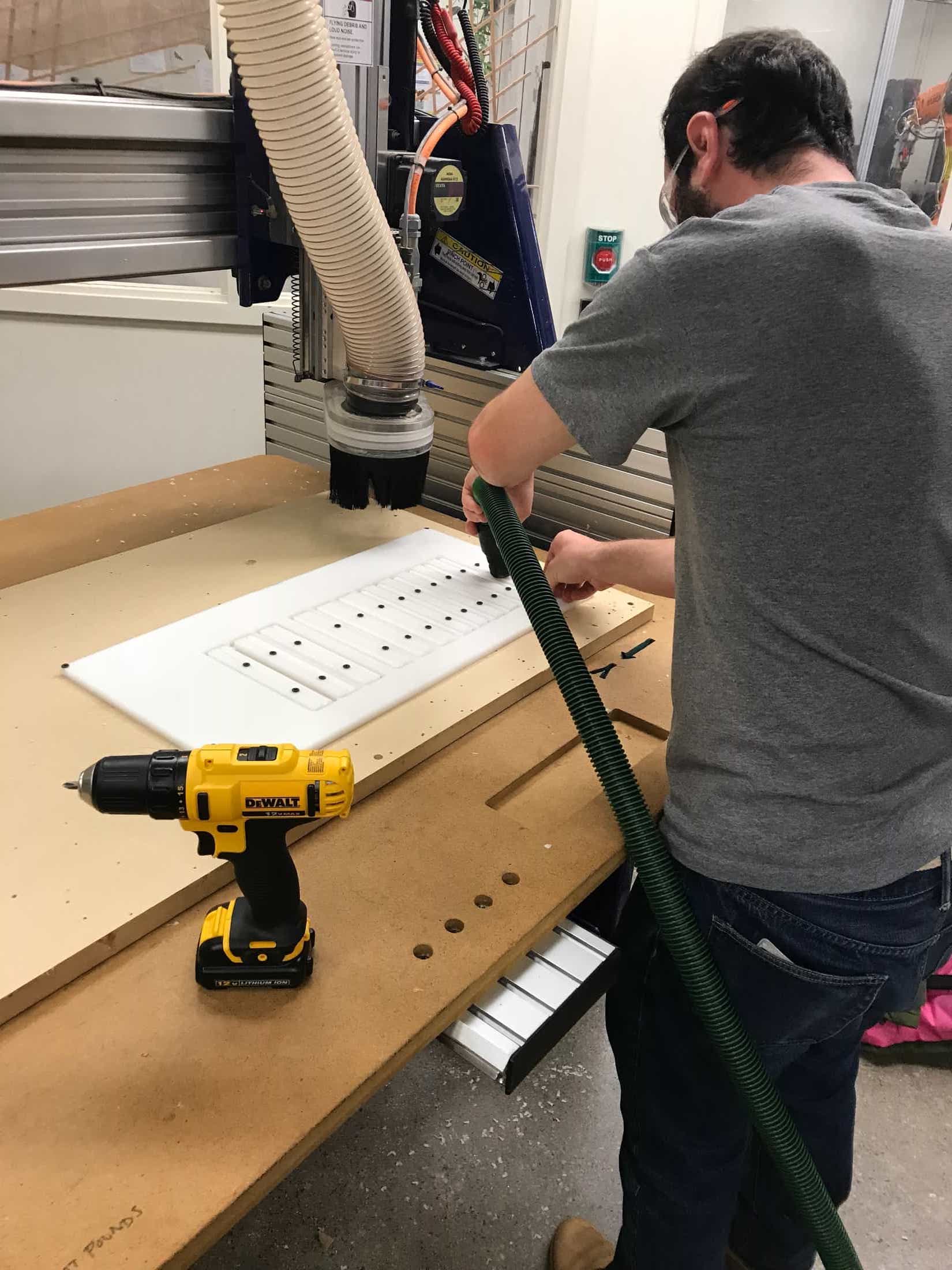
Genshaft vacuuming after a sheet of parts was finished on the ShopBot.
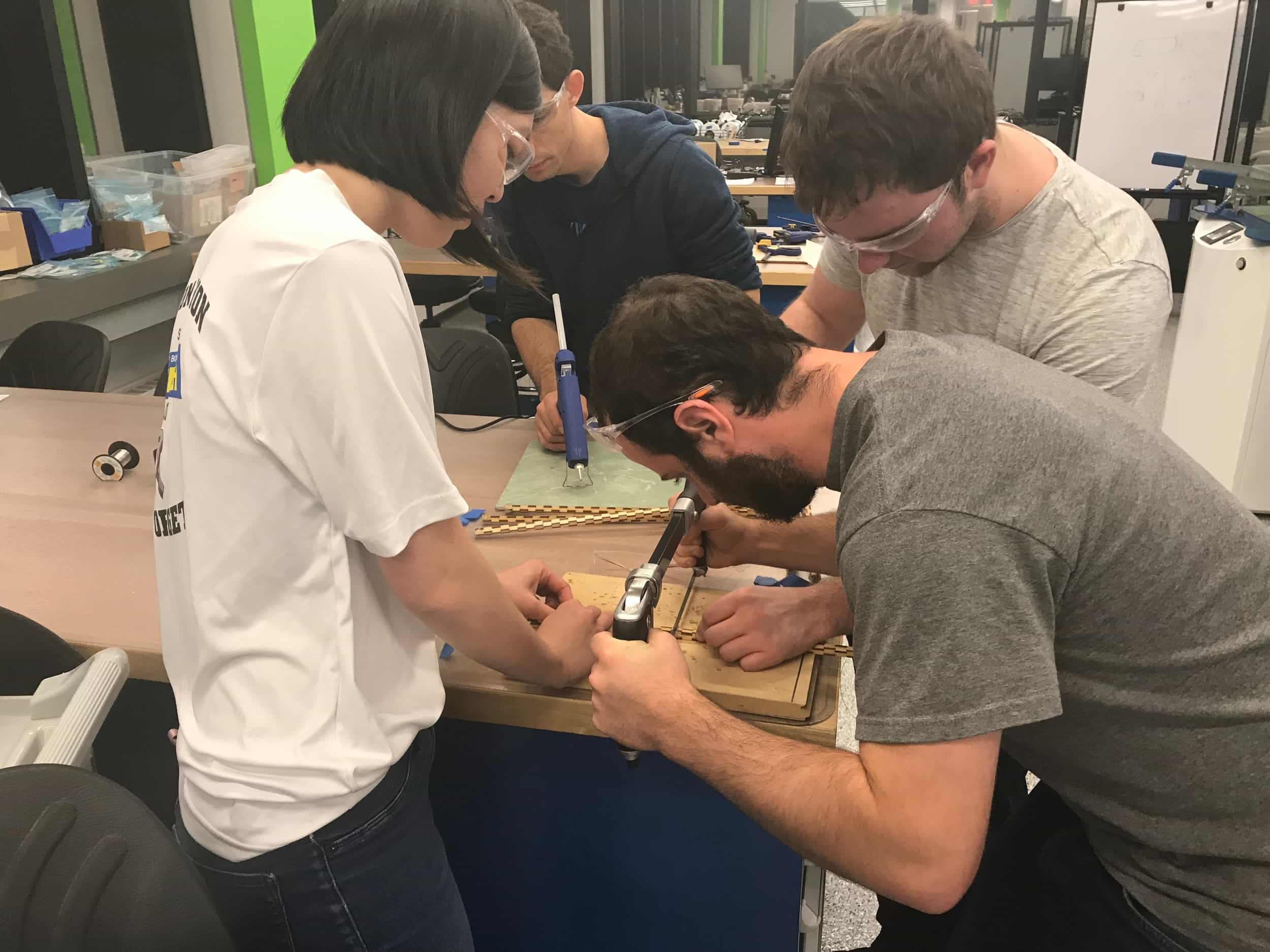
Once we had all the parts machined, we struggled with deciding how to attach everything together. Our machined parts didn't have holes for screws, so we went through a lengthy process of figuring out how to clamp all the parts for the motor mount and rail slides together. This process of connecting these parts and connecting them to the rails took a number of hours, and we had to change our strategy to deal with problems that arose. I helped measure and mark the locations for drilling and helped with drilling and clamping among other things.
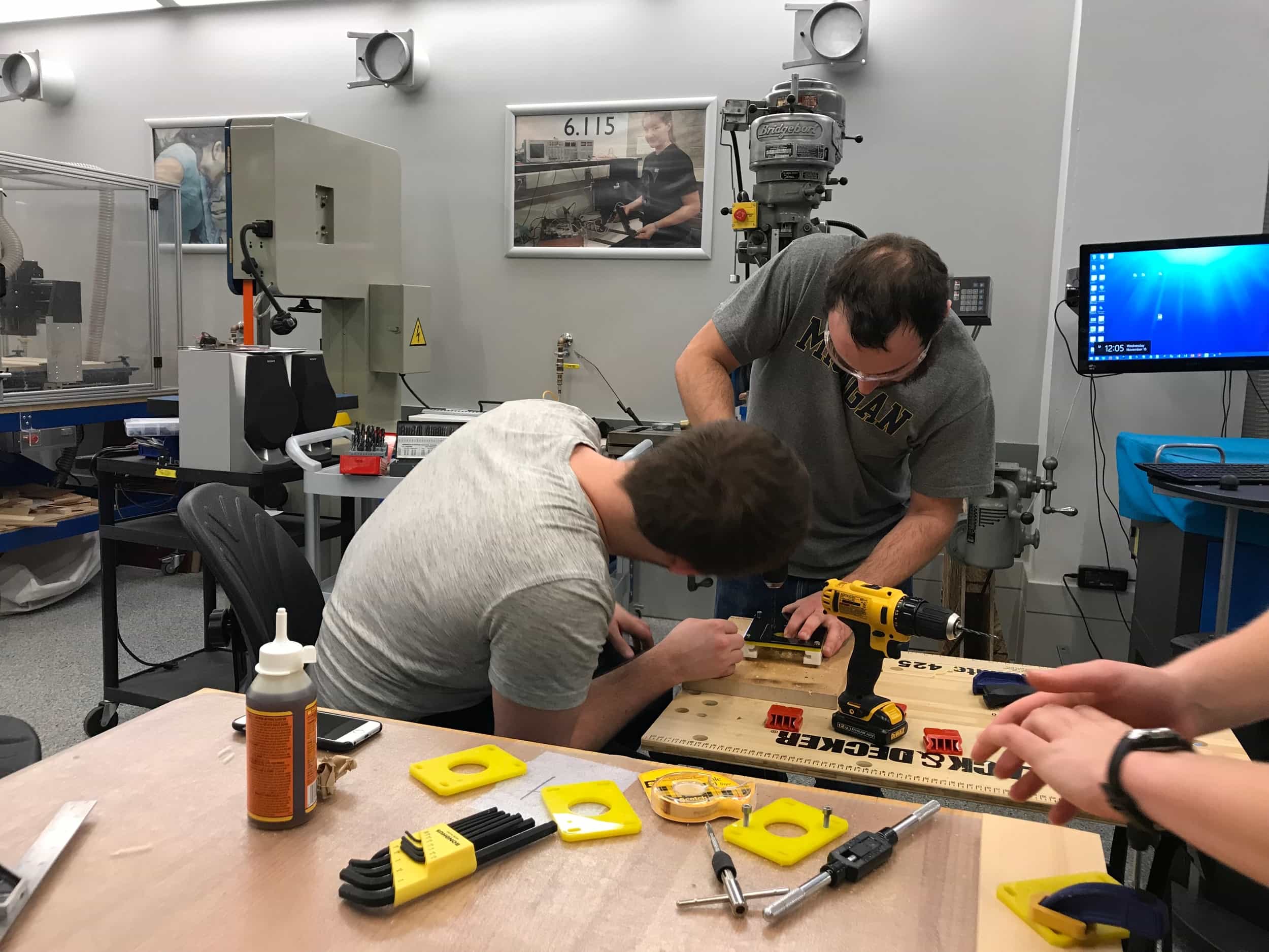
Attempting to connect the mounts.
Finally, we were able to mount the motors onto the rails. We tested each motor moving along its rail. The excitement was real when the parts of our machine began moving as they were supposed to.
After we tested each motor moving along its rail, we needed to glue two pieces to each mount to serve as the attachment points for the arms. I became an expert with Gorilla Glue and clamping to secure the arm mounts.
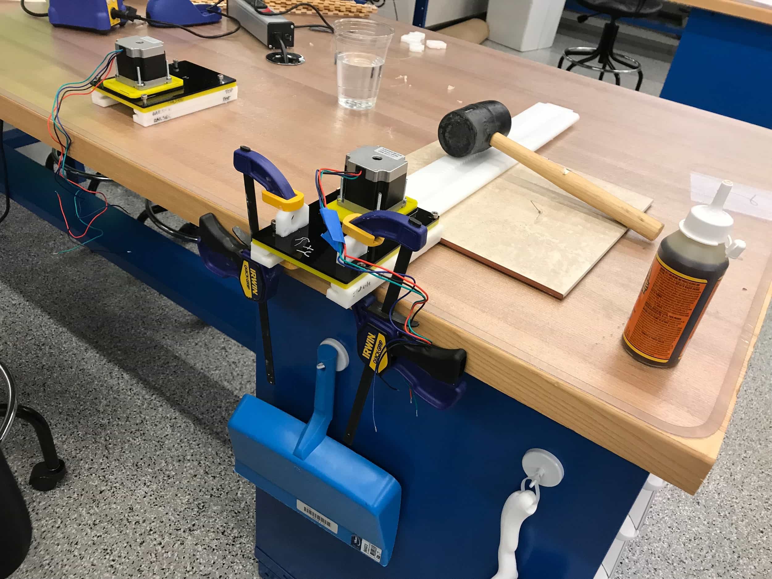
Gluing the parts to attach the arms.
Once the glue dried, we stuck the rails into the base plate and top plate. We already knew the arms would be too long, and decided they should be cut in half. We sawed them, and then reglued the new end of each arm to prevent the string from getting caught in the joints between the pieces of the arms.
Sawing the arms in half and regluing the ends.
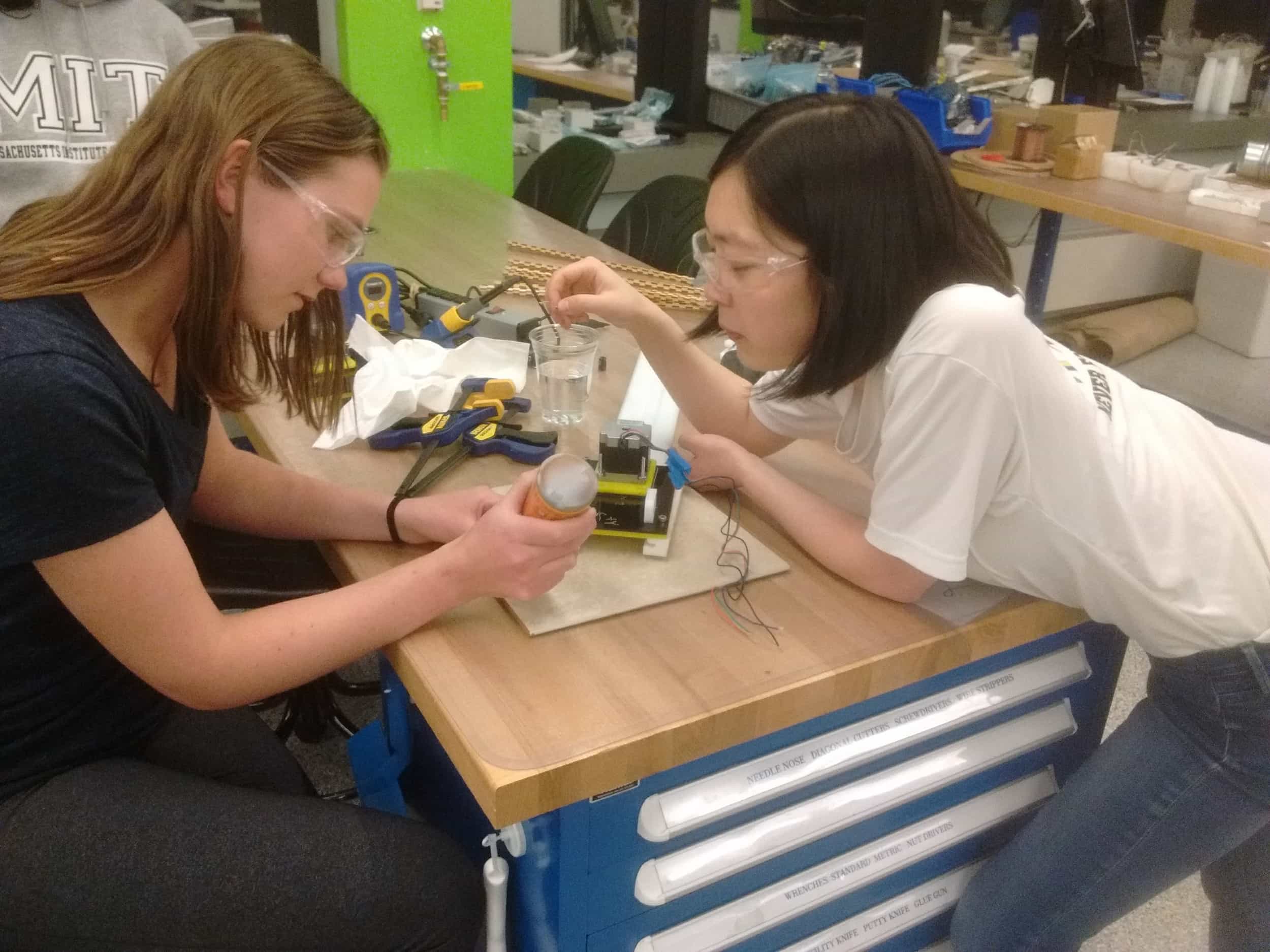
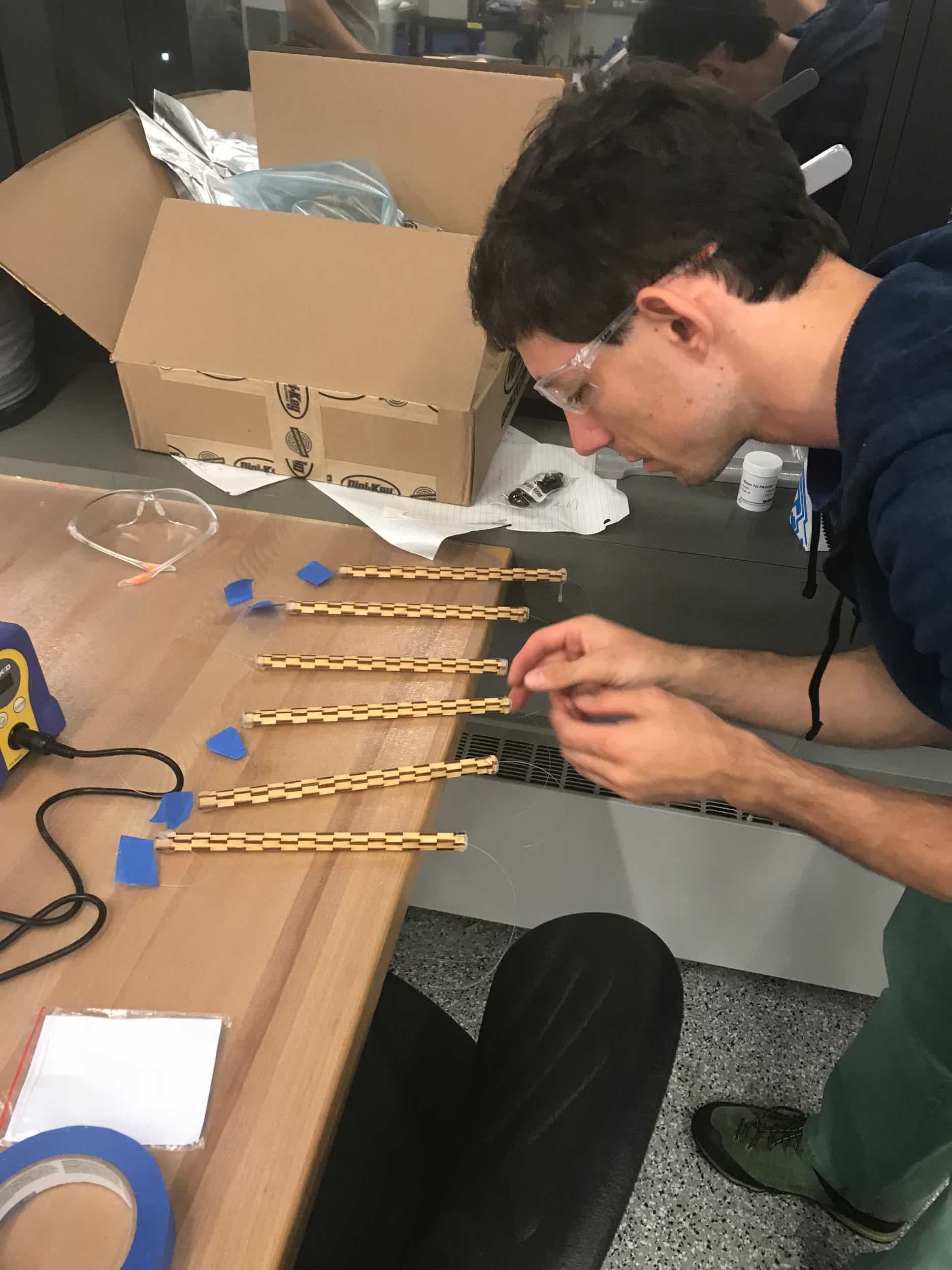
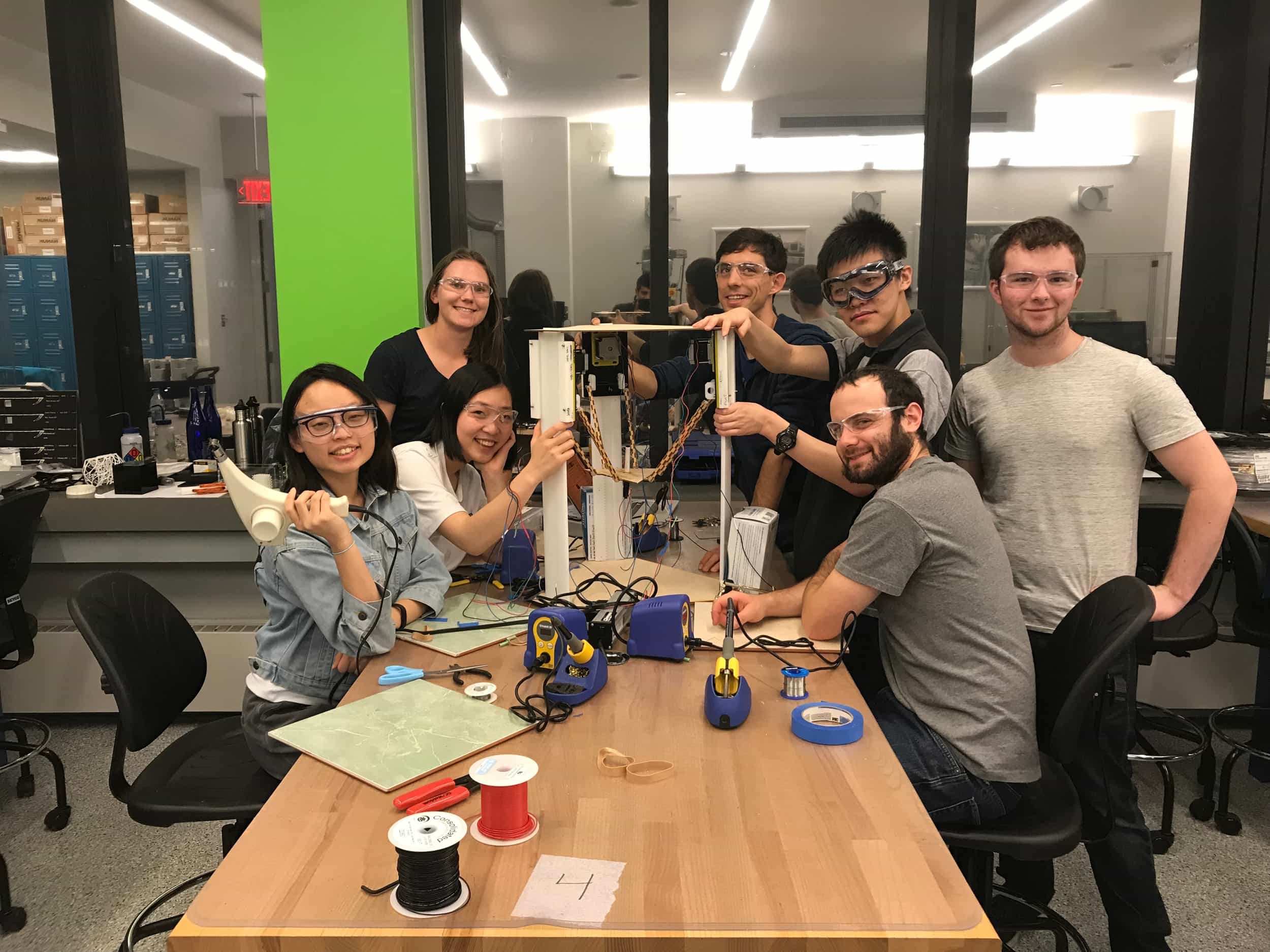
We also realized we needed to extend the wires attached to the motors so that they would be able to reach the TinyG where we were going to mount it, so we got out the soldering irons, heat shrink, and heat gun to do so. We were able to attach the arms to the mounts and to the end effector plate, and we used some machined parts that didn't make the cut for our actual machine to prevent the motor mounts from falling too low.
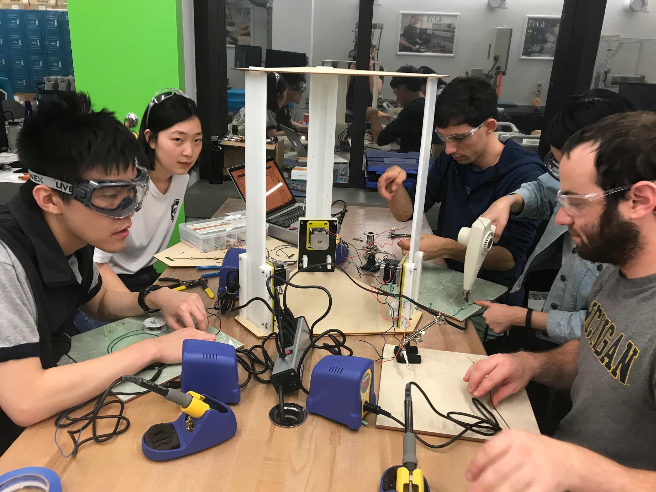
Extending the wires.
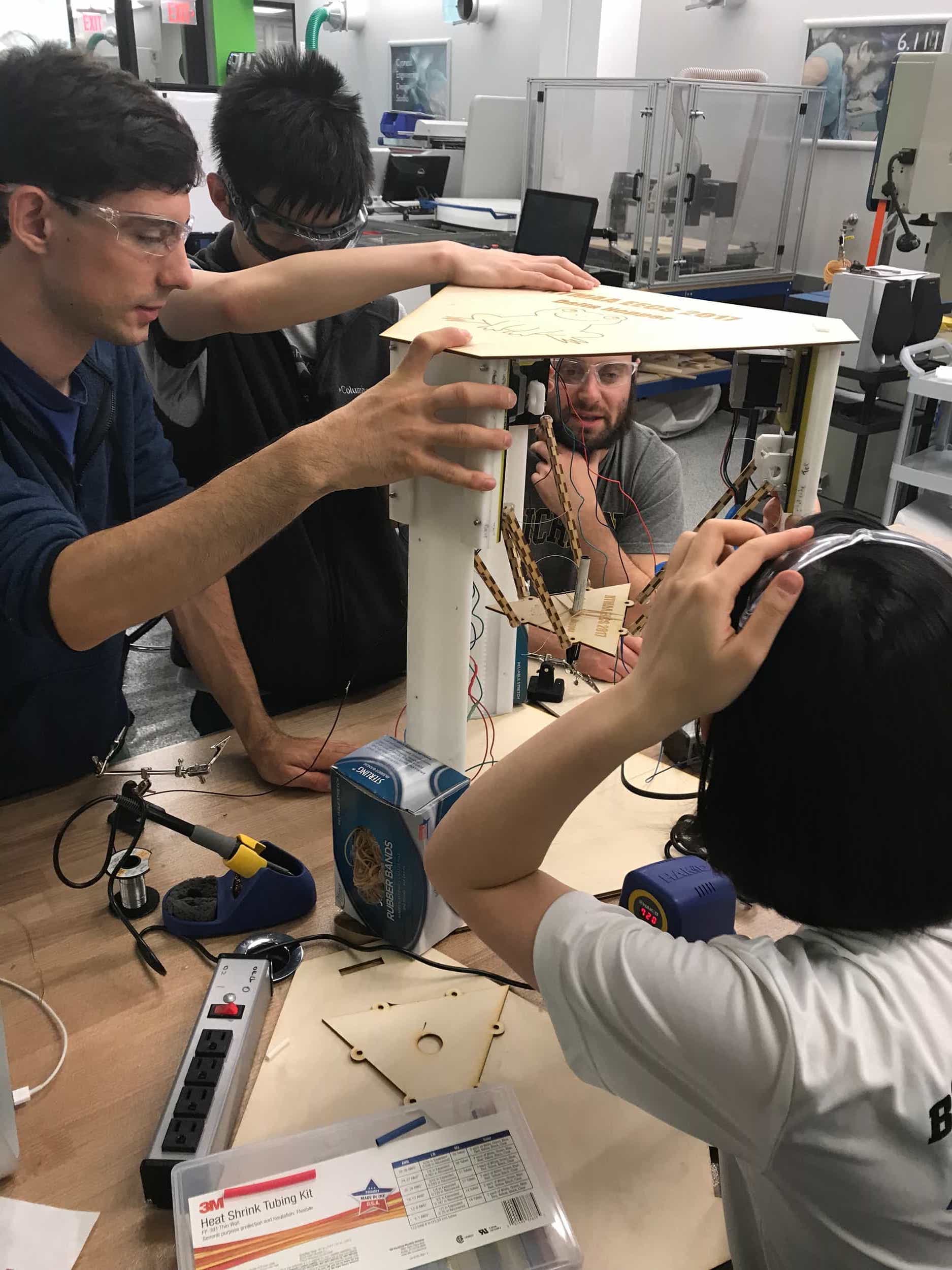
Attaching the end effector plate.
By 3 or 4 am, we had something that resembled a machine.
It's a machine!
And here is the video Natalie compiled of our Delta Hopper actually moving.