first bad idea
second bad idea
Make an Enigma Machine!
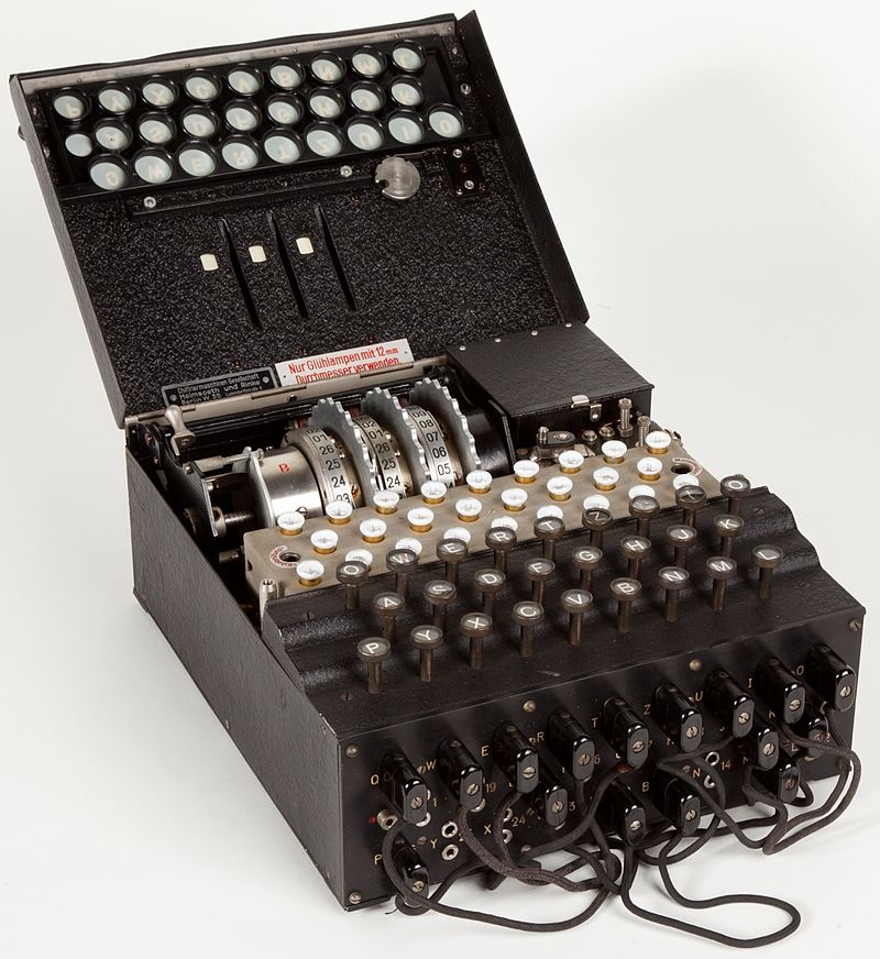
The Enigma Machine was a device used by the Germans in WWII to encrypt and decrypt messages. Here is a very consise and informational video about what the Enigma Machine: video link.
To summarize, the Enigma Machine generates its cryptrographic power by a series of wheels and a plug board. The wheels scramble any input, and on a key press the rotor will turn. One consequence of this is that 'A' may be encrypted as 'B' in the beginning of message by may be encrpted as 'C' later in the message. It all depends on what the initial settings of the rotor is.
(Historically, the rotor settings were distributed by paper. Everyday, a different setting was used. This constant changing of the settings meant that even if you were able to decrpypt a set of messages, a whole new scheme would be in place the next day. With that in mind, any effective plan to break the Enigma Machine would need to do it fast.)The next tier of encryption involved plugboard settings. Up to 10 pairs of letters could be swapped preceding manipulation by the wheels. This adds a lot of complexity. A massive team of code breakers (including Alan Turing) at Bletchley Park would break the Enigma Machine. Although it is an outdated method of cryptrography, the story of the machine remains impressive.

Building it
This project can be modularized into three major parts.
1. The keyboard input. The goal is to have a button for every key. The output should be mapped into 5 bits. This is so that a
microprocessor can easily process it.
2. The microprocessor. The goal is to receive the keyboard input and to perform mathematical operations on it. The output is the LED Display.
3. The LED display. The goal is to light up a single letter.
4. The housing. It is a simple box to encase everything.
5. The network interface. Be able to configure the microprocessor from a laptop through ftdi.
Parts 2,3,4 are completed. Parts 1 and 5 I did not finish in time.
Keyboard Input
There are 26 characters. The neat thins is that only one character can be pressed at a time, so the goal is to encode this input into 5 bits. My intention is to map every character into a 5 bit string. So A -> 00001, B-> 00010, and so on. My plan was to use an 74LS148 IC, which is an 8-to-3 encoder. Then by combining several of these, I could get a 32-to-5 encoder.
I didn't get around to making the actual physical button inputs. To test being able to receive inputs, I just set several the pins with another voltage source.
Input Processing
This acts as the message scrambler. Once the microprocessor receives the character input, it begins to simulate the phases of message encryption.
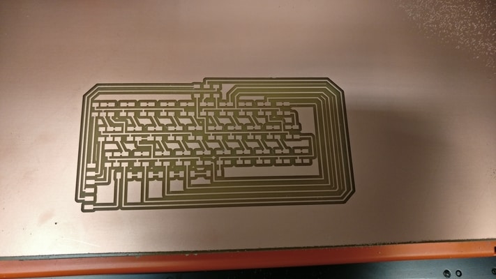
I designed all the boards using Eagle.
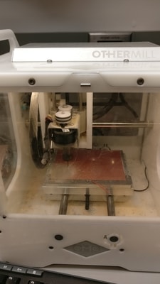
I tried to use the OtherMill for the first time, but it didn't turn out too well. I went back to using the Roland SRM 20.
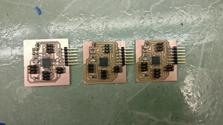
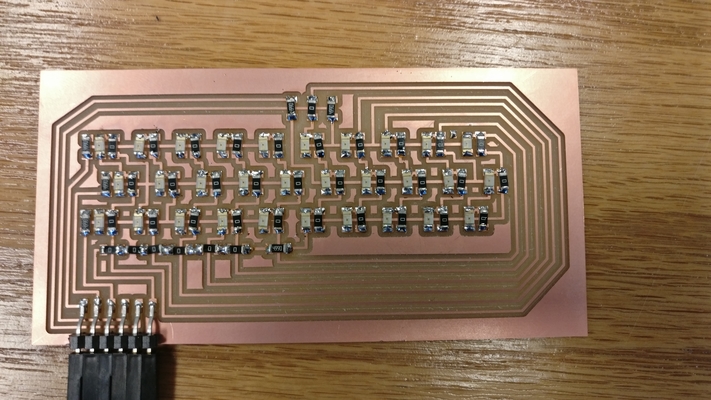
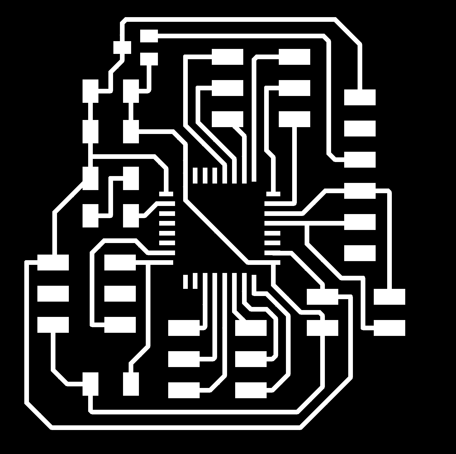
I premptively made 3 of the same board. The way I had made it, they were very general purpose microcontrollers with 6 digital input pins and 6 output pins. I also added a serial bus port should I choose to put multiple of them together. At the very least, I would need 1 one these to read the keyboard buttons and output to the LEDs.
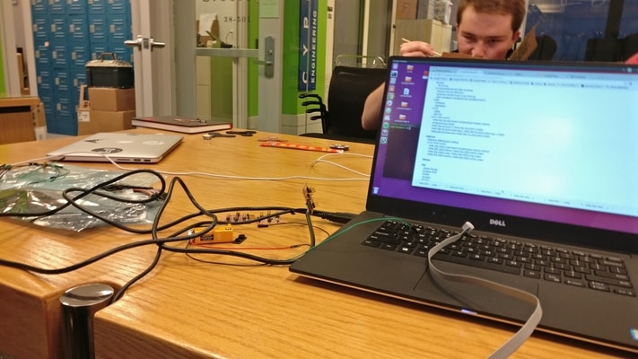
I ran into a setback trying to program my board. I had tried too use my usb progammer I made, but it couldn't communicate with the ATXMEGA16E5. It did fine trying to program boards with the ATTINY44 and ATTINY45. This would take a while because I didn't know where the issue was. I tried remaking the programmer and the boards but it didn't work. Then I remade the hello world board for the ATXMEGA16E5 and it still didn't work. I finally tried to use a different progammer type. I used the Atmelice Programmer. The exact setting is to use the atmelice_pdi.
I was able to program a simple encoder. The idea is to replicae the enigma exactly. Each wheel basically maps a letter into another letter.
The decoding process was more complicated and I wasn't able to get around to it. One thing to keep in mind is that on every keypress, the wheel ends to rotate. The intention was to use my laptop to interface with the board. I had wired the TX and RX cables and a serial bus connection, so that I could program the intial state of the board. The user would be able to see the current rotor positions and also be able to configure the enigma machine.
Letter Display
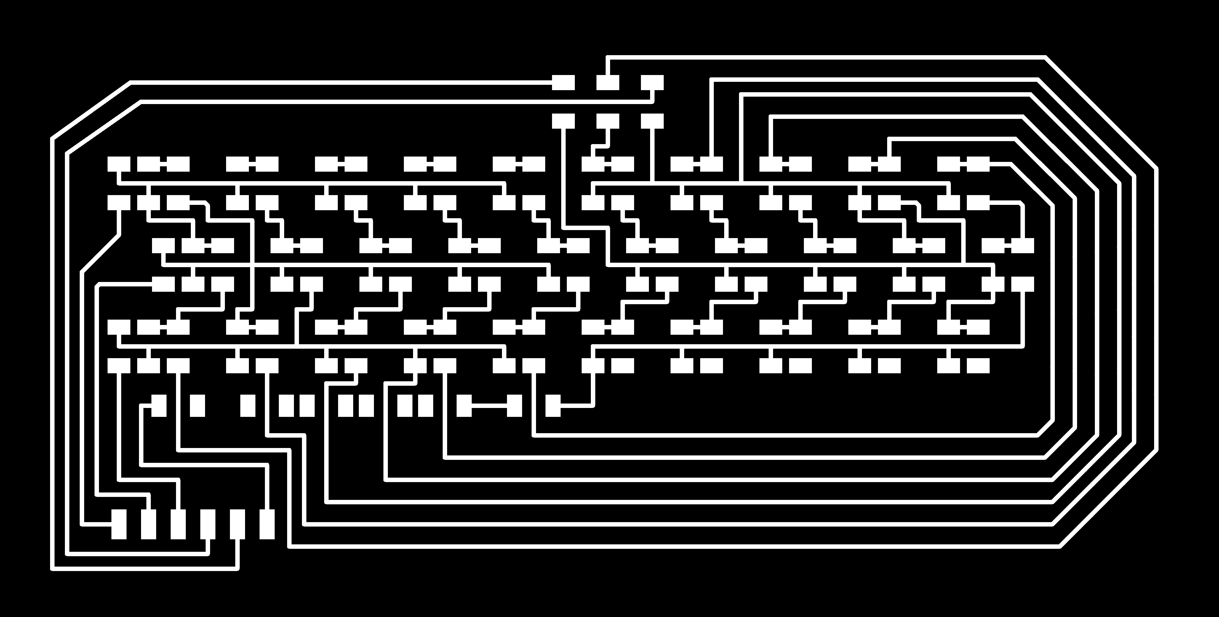
Once we know what the encrpted character is, we now need to light it. The trick here is to implement a charlieplexed circuit. With only 6 pins, we can control 30 LEDs, which is sufficient. I started by looking at the 20 LED charlieplexing reference from here. I would need to expand on it. I milled a board that implemented only the circuit.
My first attempt at the LED matrix turned out to be a disaster.
It turns out I had incredibly miswired the LEDs. After fixing the first one with a bunch of hacks, I was able to get the LEDs to all work.
Then I remade another board with the correct wiring.
This one works, and it is even aligned to the housing.s
The Housing
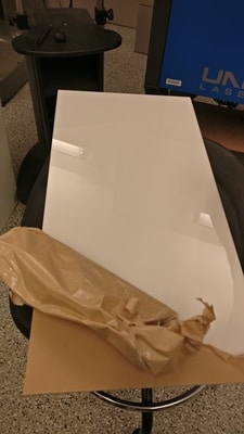
The box frame was made by laser cutting an acrylic sheet. TA Gavin showed us a cool resource to make a simple 3D box (source). The trick here was that I had to be very careful with the letter spacing. Of course, I chose a monospace font. The spacing would be important when integrating with the display and the keyboard buttons.
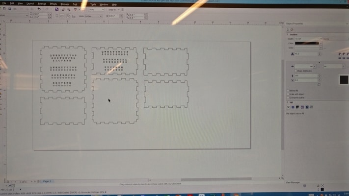
I used the box as a starting point. Then I overlayed the text in the correct position.
The process here is to remove the top layer and leave the bottom on there.
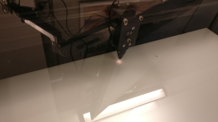
Here is the laser cutting in the process.
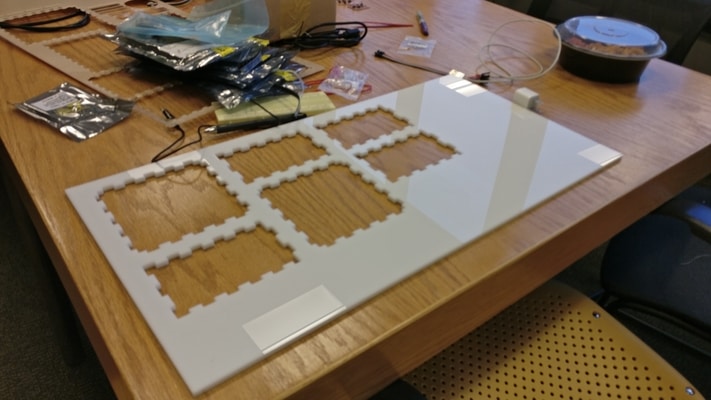
The top contains two parts, the lightboard and the keyboard.
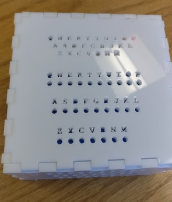
Here you can see a video of the LEDs rotating through every character. EVERYTHING IS ALIGNED! I'm actually impressesed that I was able to do this. Underneath the LED array is actually 30 units.
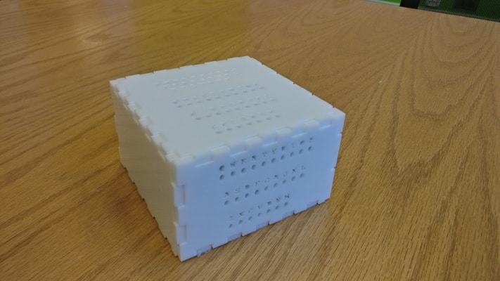
At the front, you can also see another keyboard panel. This is to implement the plug board.
Cost breakdown
Here is a link to a sheet . So most of the eletronic equipment doesn't cost that much. The only thing that surprised me was the cost of the acrylic sheet. The total cost is around 20 dollars, which is pretty good.
Files
board_traces.png
board_outline.png
charlie_traces.png
charlie_outline.png