Kenny Friedman, Final Project
Split Flap Display
Concept
For my final project, I wanted to make a split flap display. I got most of the way there, completing an early version of the display.
Here's what a professional split flap display looks like:
Results
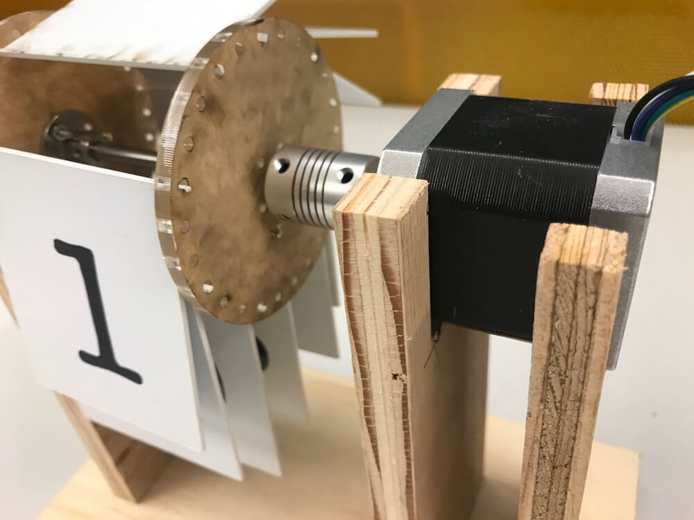
Here's what my split flap display looked like, the day before final project demos.
TLDR Results
I made a prototype split flap display (with more split than flap). I used the following tools/methods to create it: vinyl cutting, laser cutting, EAGLE/PCB design, embedded programming, output devices (stepper motor driver), and some future directions for communication and networking.
Construction Intro
This entire project took a lot longer than expected in just about every way. But that's the maker life! Let's dive in.
The construction involves deciding on a motor, making a structure around it, making an axel, making the wheels, making the flaps, making the numerals, and assembly. Not to mention the motor wiring and board, which I will discuss in the electronics section.
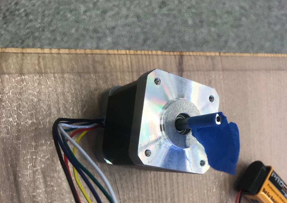
Motor
For this project, I decided to use a stepper motor. I explained the details and setup of this part in Week 10: Output Week.
Even though I already had this part figured out from week 10, I had major problems getting my motor working. In fact, the cause for most of my delays in the final week.
For multiple days, I couldn't get my motors working both clockwise and counterclockwise. I thought the wiring was wrong, but I now believe it was my board. The more I tested, the more problems I ran into. I eventually decided to "start over" and re-mill the board.
The rest of motor process can be seen in my Week 10 page.
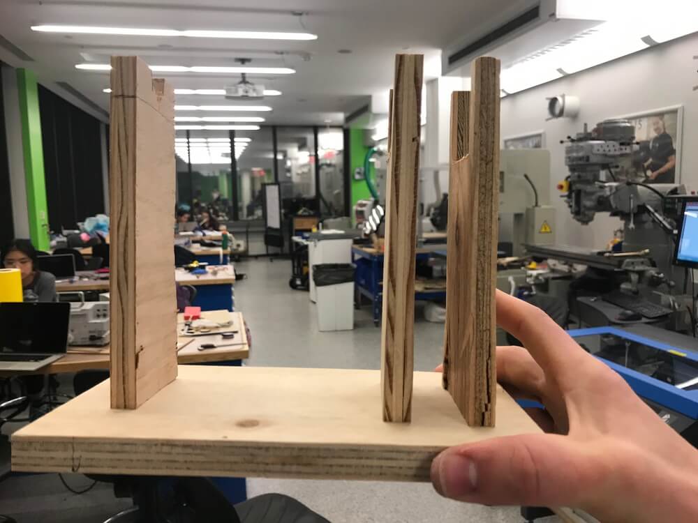
Physical Structure
The physical structure was a bit of a disappointment. I wanted to laser cut a press-fit kit to make a box, or 3D print a structure for the entire box. Unfortunately, I ran out of time.
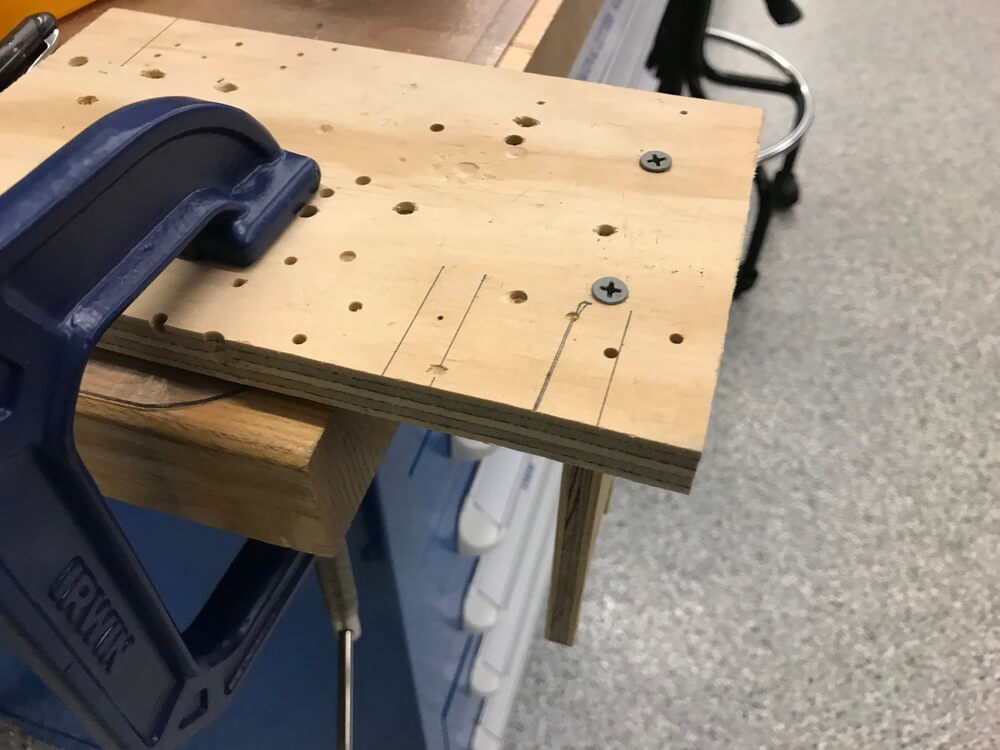
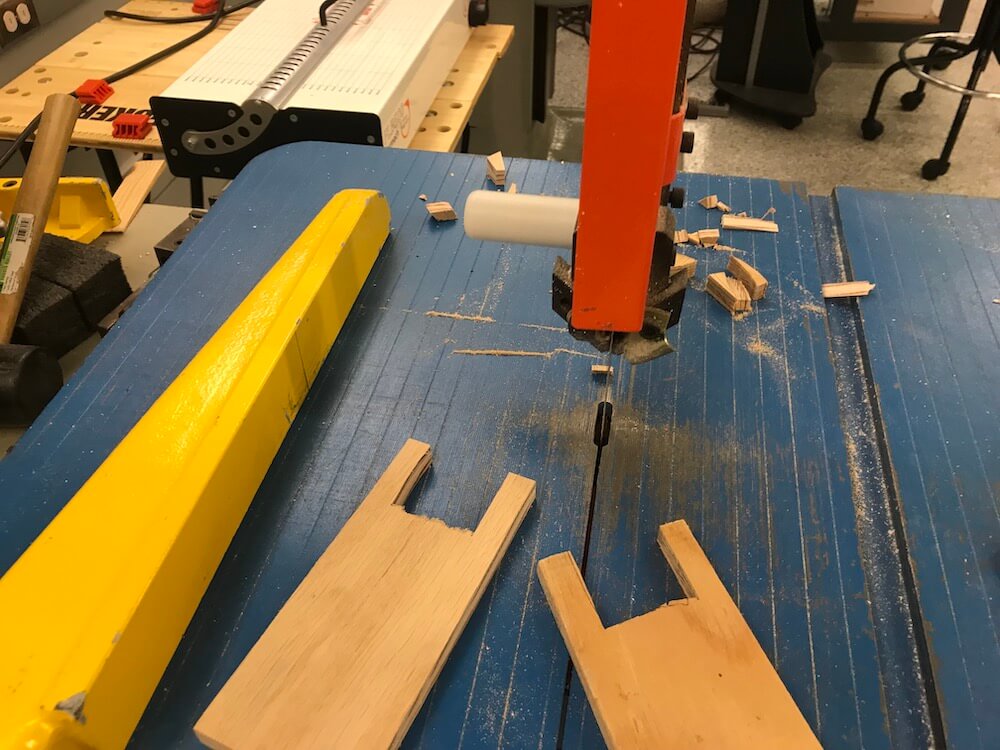
In a pinch, I found scrap wood and made a stand for the display. Section Leader Zack showed me the ropes for using the EDS bandsaw.
The structure is very straightforward. It's not the prettiest thing in the world, and it's not digital (the only part of my project that isn't) - but it does its job. I made it out of scrap wood, and used the band saw to take three 6" tall pieces of roughly equal width. I then cut insets in the three pieces. Two of them are 2" deep cuts, to hold the stepper motor. The third is a 1" deep cut to allow the axel to rest on a pivot, which will be described further in the next section.
In the future, I would love to make the physical structure out of press fit construction kit of cardboard or acrylic, similar to what we learned in week 2.
Making an Axel
The Axel contains the only parts I purchased outside of material I either created myself or was available in the fab inventory.
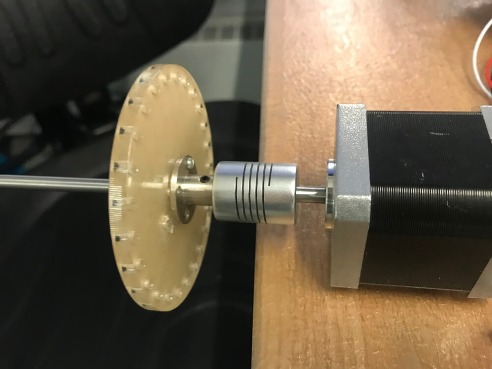
The stepper motor from the fab inventory has a very short shaft. It's cross section is a circle (there's no flat edge, like some shafts have). I needed a much longer axel, and I decided the best way to do this was to use the same size shaft (5mm diameter).
After a bit research, I found out that I need to use a coupler (a $5 part) along with a 5mm shaft (a $2 part).
Finally, I needed to connect the axel to the wheels. They needed to connect in two ways. The wheels need to connect horizontally to the axel, so they don't shift in place. They also need to connect radially, so that when the axel turns, the wheels also turn. The simplest solution to this is to use a universal mounting hub (a $10 part).
The axel, coupler, and mounting hub could have been 3D printed. In fact, 3d printing it on a high resolution printer would be the ideal way to accomplish this. But factoring in my time budget, it made more sense to purchase these parts, to focus on the other aspects of the design.

Wheel Creation
The development of the wheels for this project was one of the most fun. I was able to laser cut the wheels, which gives me sub-millimeter accuracy, and a very easy way to rapidly prototype changes.
For example, on an early iteration (I went through 6 wheel designs), I made the outer holes (where the flap inserts will go) too small. I was quickly able to modify them and re-cut. Out of all the tools I learned this semester, I really love the laser-cutter.
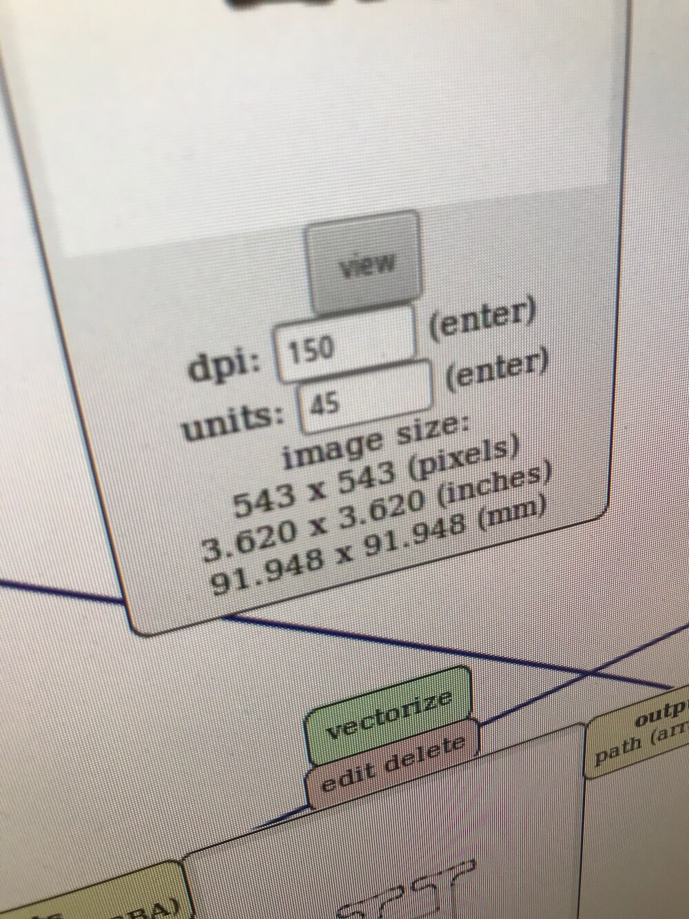
I made the designs for the wheels in Sketch, my go to vector editor for the Mac. I've used Sketch a lot before, so it wasn't new to me, but I did learn one useful feature. At first, I wasn't sure how to get the evenly spaced outer circles of the wheel. Eventually, I came across a well-hidden feature tool of Sketch called Rotate Copies, which lets you make multiple copies of a layer on a pivot point. Perfect!
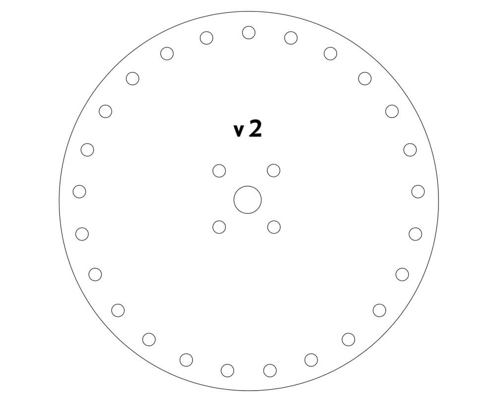
The inner hole of the design is the central axis that the axel fits through, while the four surrounding holes are for the previously mentioned
I laser-cut the design using 1/8" acrylic. But I think either thicker or thinner acrylic would have worked... this is one of those dimensions that no other part of the system relies on, so it's really variable within reason.
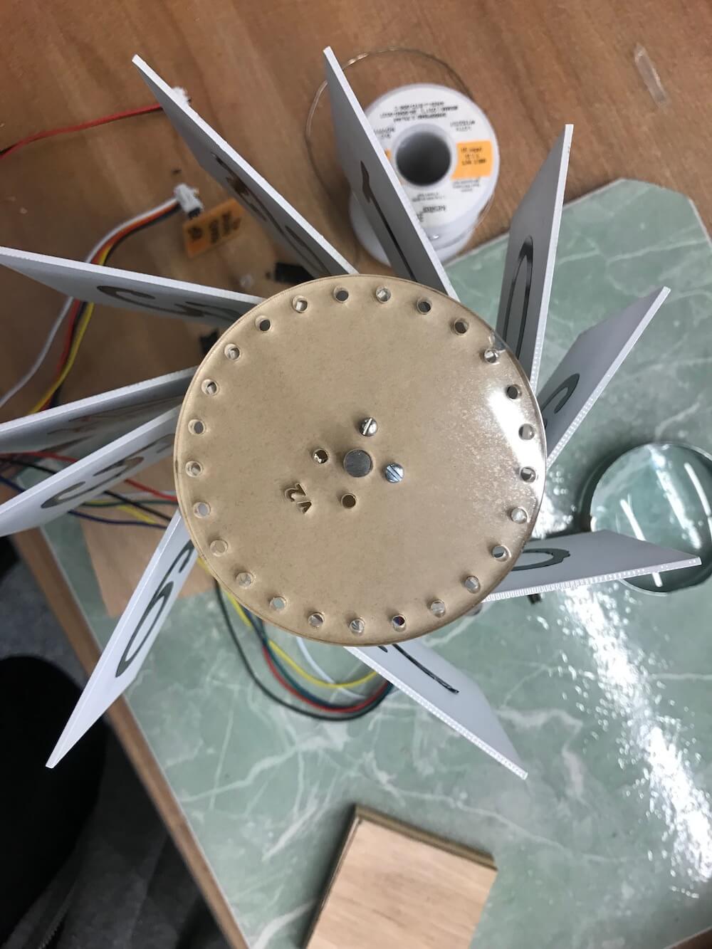
You'll note on the design below it says v2, this is actually v6, but used to differentiate between v5 and v6, which are nearly indistinguishable from sight. (v1 through v5 were all obviously different when held next to each other. The difference between v5 and v6 was sub-millimeter changes to the locations of the 4 mounting hub holes, because the hub didn't fit in v5.
Making the Flaps
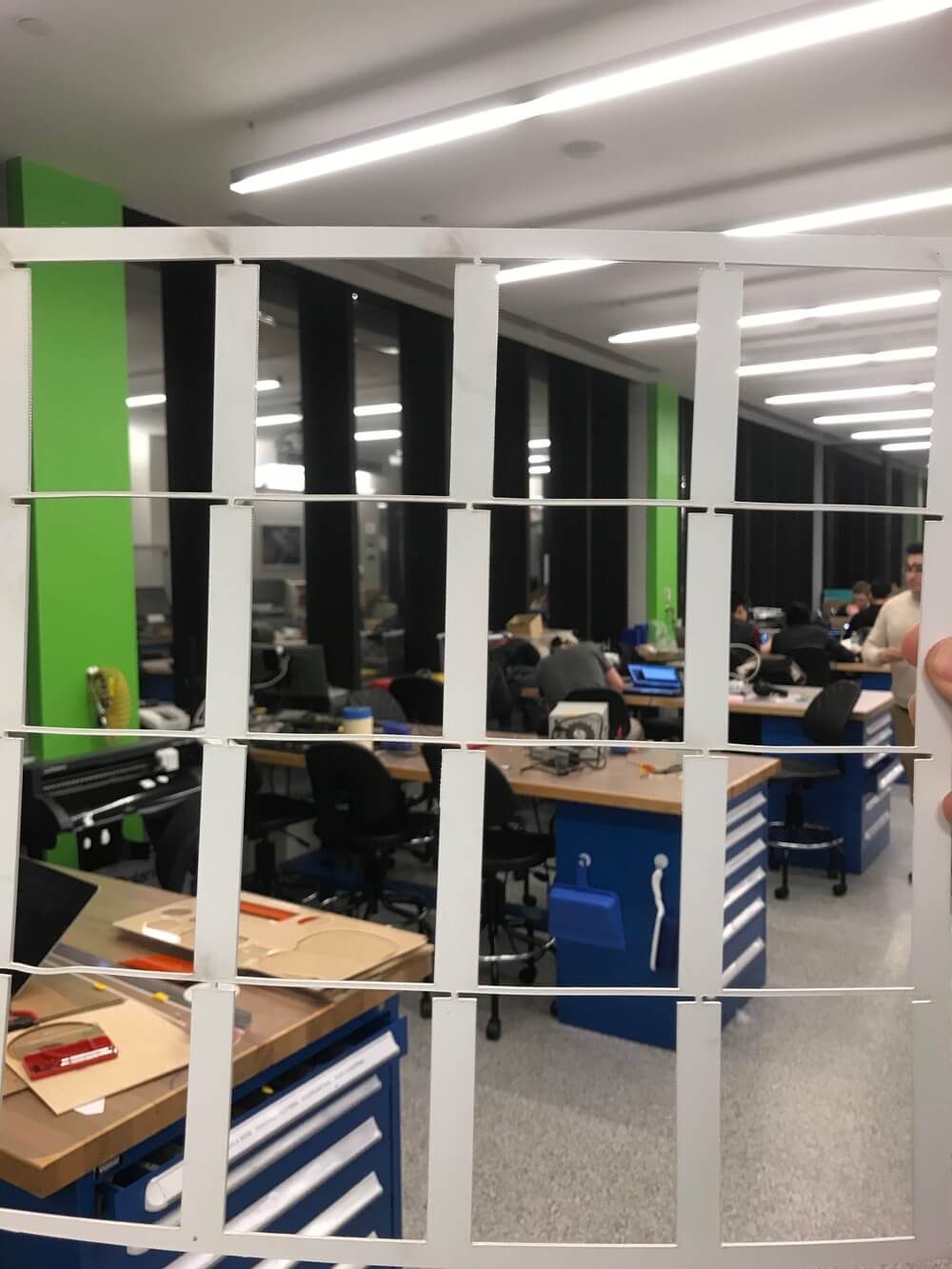
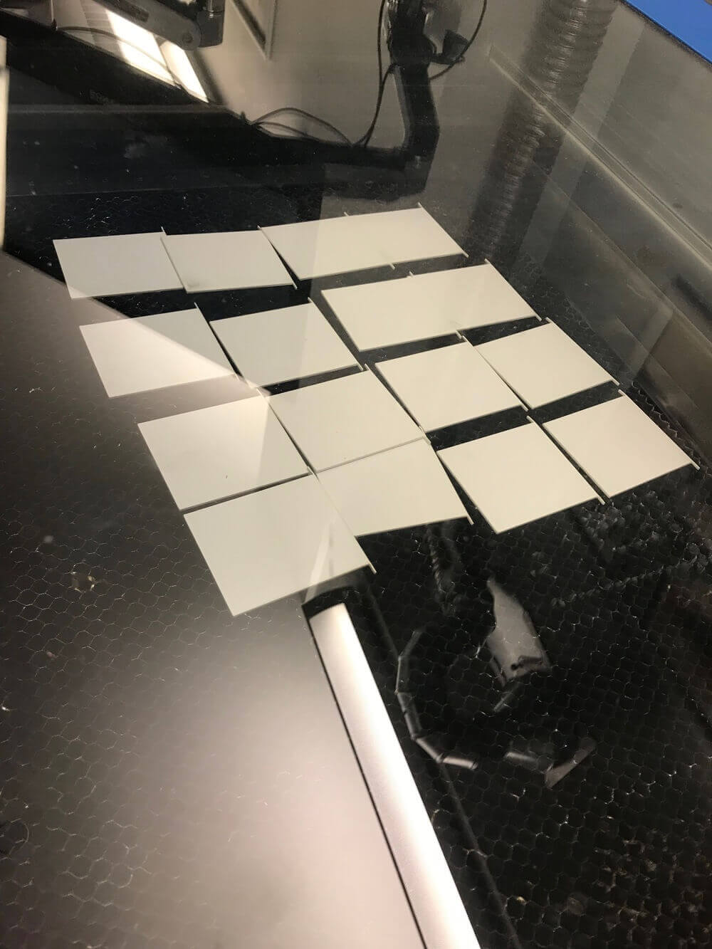
In the final iteration before final project demos, I ended up making the flaps out of polystyrene, laser-cut to the correct shape.
Early iterations of the display used paper, and later iterations used acrylic. The goal material would be thin enough to have many slices or "flaps" next to each other. It would also be nice for the material to be somewhat flexible, so that the nice slapping sound of a falling flap will look and sound pleasant.
I found polystyrene in the shop, and Shop Leader Dave told me that I was able to laser-cut the material. The trickiest parts are the top left and right corners. There needs to slots for the flaps to fit into the wheel. I decided that the easiest way for this to work was to keep the width of the side extensions roughly equal to the width of the material. That makes for the "roundest" possible square, which will allow for rotation when the flap falls to display the next letter.
One thing to note: because the flaps need to rotate within the side wheels, they can't be physically attached to the wheels. The only way the flaps stay in place is because of the horizontal lock of the side wheels, and the flaps that are larger than the inner length between the two side wheels.
One of the biggest problems is that the edges of the flaps are very, very brittle. Like a 1/64" mill bit, if you drop it at all, it will break. You can see an example of this in the final photo of this section.
Numerals
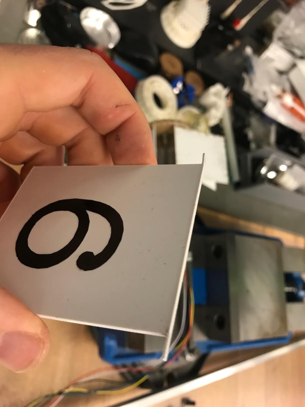
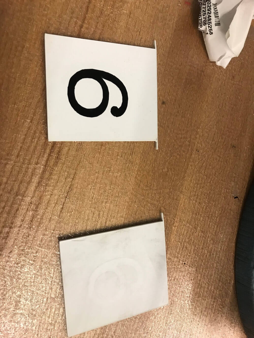
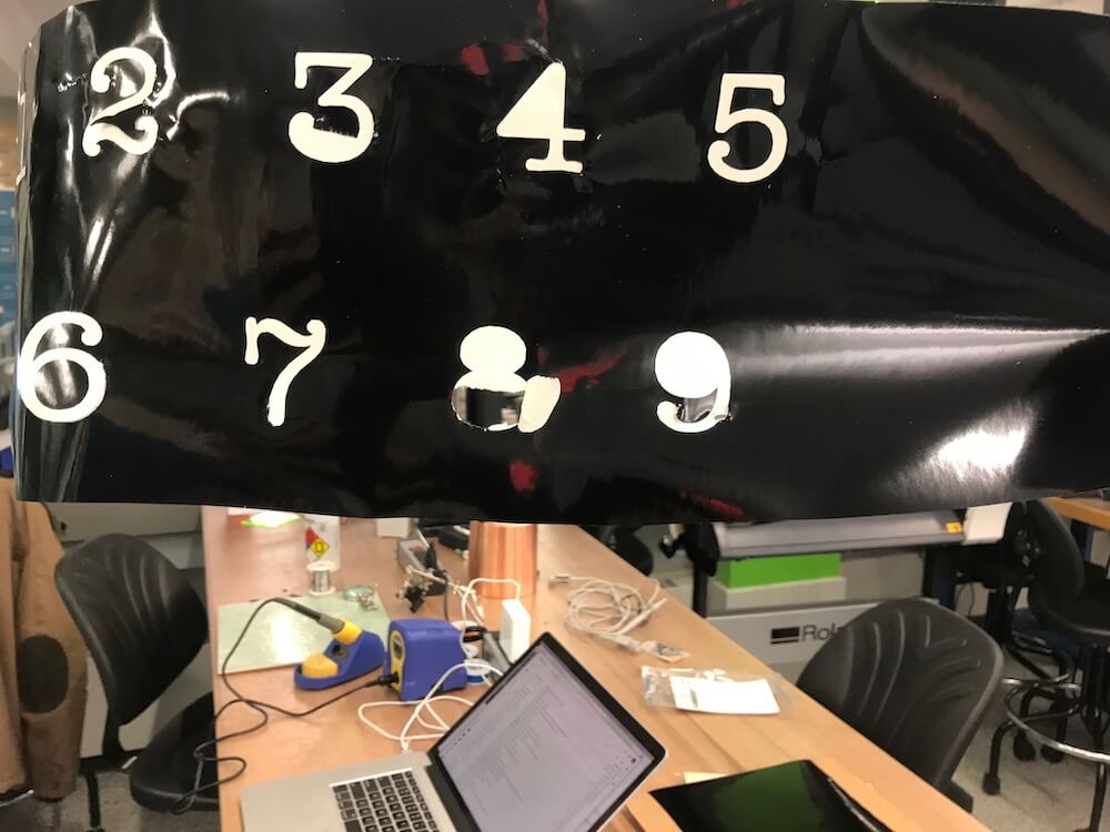
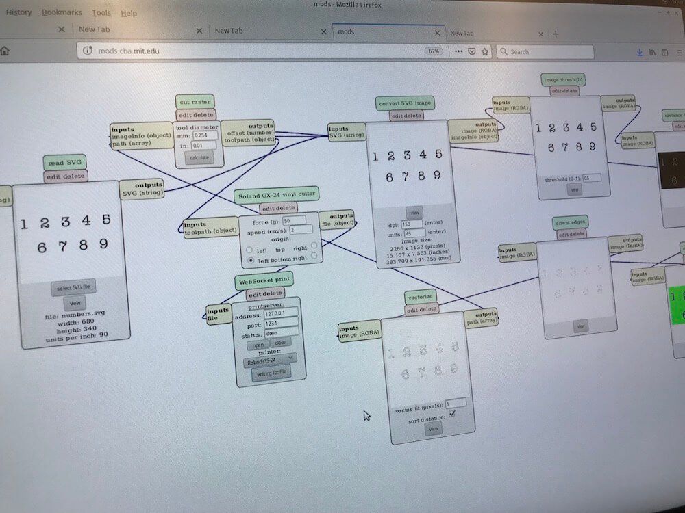
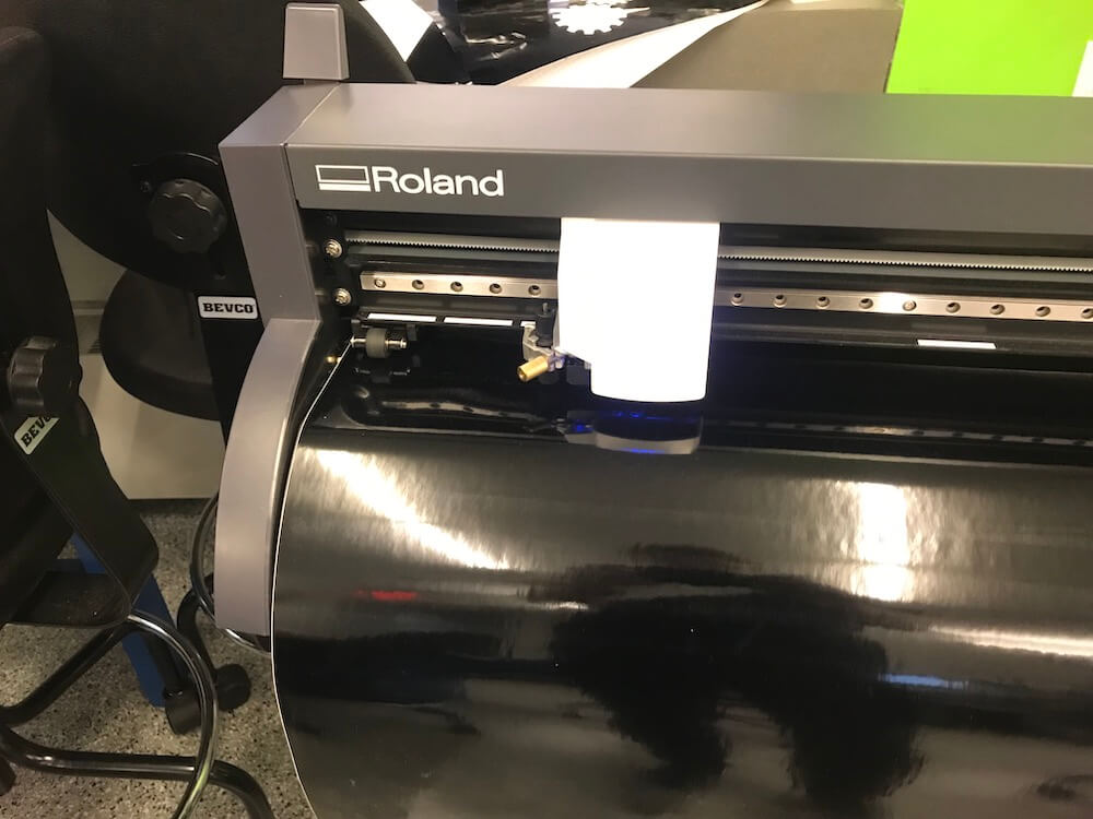
I used the vinyl cutter to cut 10 numerals, 0 through 9. This was very straightforward. The vinyl cutter appears to be a great tool - I'm glad I got a quick intro, and would love to do more projects with it.
Assembly
All the components listed above were hand assembled, the second non-digital aspect of the project. For a sense of the final assembly, watch the videos below!
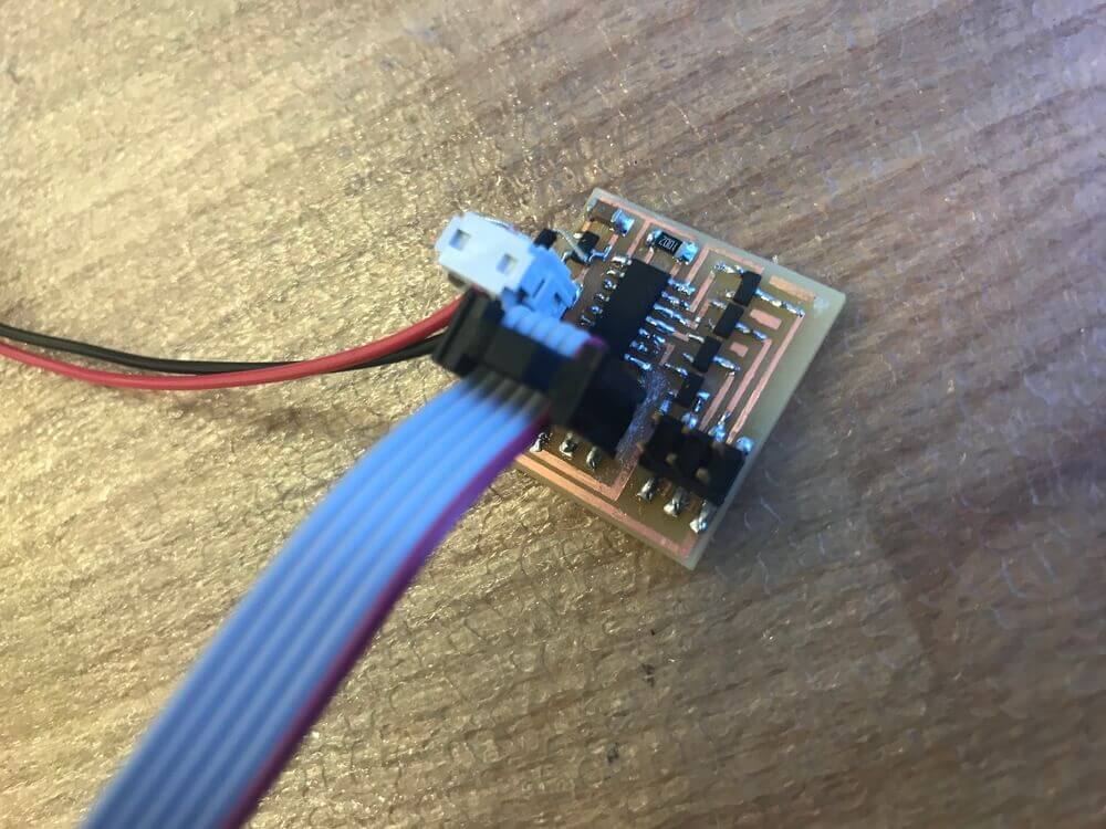
Electronics
Time to talk about electronics, a surprisingly tricky part of creating a split flap display.
As previously mentioned, I needed to do a lot of debugging to get the stepper motor to work.
The wiring of the uni-polar stepper motor was tricky enough, but I solved that in week 10.
For the final project, I wanted to move from basing my code from Neil's stepper motor C code to using the Arduino C IDE library. It uses higher level frameworks, which increase the size of the code, but supposedly make it easier to iterate and rapidly prototype.
However, I simply could not get the Stepper.h Arduino library working. There should be only 3 commands I need:
- Stepper myStepper(stepsPerRevolution, 8, 9, 10, 11);
- myStepper.setSpeed(60);
- myStepper.step(-stepsPerRevolution);
But I could not get this to work. In the end, I reverted to plain raw C, based on Neil's original code.
Where Do We Go From Here
I am very excited about all the skills I learned in this class, especially EAGLE, PCB Design, and PBC milling... which really felt like the missing tools on my EECS toolbelt. Here are many more ideas I have for things I want to do with this project:
-
Turn the "holding structure" from a one-time assembled part to a digital fab process (laser cutting wood, most likely) so that making more displays characters will be easier.
-
I would also 3d print the axel and the mounting hub, instead of needing to buy them.
-
Then, I want to create many more display characters, so that I can display a single message all in a row. With the final step being a digital process, making more characters should be straightfoward.
-
Next, I want to create a communication system (probably a network bus), so that a single "motherboard" style board can control all of the individual characters.
-
After that, I want to take my input week project, and connect it to the a typewriter, so that the motherboard-board will get input characters to ouput to the split flap display.
-
And then, I want some "computer smarts" in the motherboard, so that the system doesn't just display the characters typed, but is able to compute. For example, typing "2+2" would not display "2+2", it would display "4." In a future iteration, it would be cool for the system to run a LISP dialect... but that might mean writing my own lisp intrepreter for an ATTiny... which might be hard.
-
Finally, I will have a digital computer with a mechnical input and mechnical output... the original vision.
Results
To conclude, once again, here are the results:
Addendum
The final project presentations took place, and my split flap display worked right on queue. Here's a video from the presentations.