input devices
This week's assignment was to measure something off a sensor on a board we designed.
The sensor I'm using is a phototransistor, which is a light sensor. A phototransistor is, get this, a transistor where the current going from the emitter to the collector is dependent on the level of incoming light the sensor receives.
Before getting into making the week's assignment, I decided that I needed a serial to USB converter, so I made the FabFTDI board. This way, I no longer have to be in the shop to program the boards.
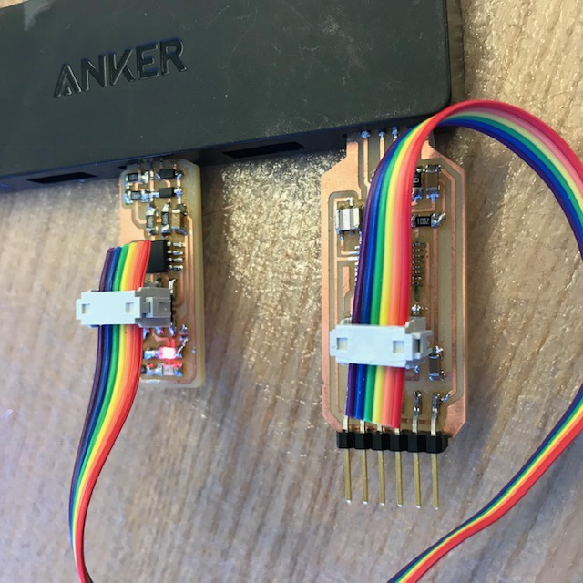
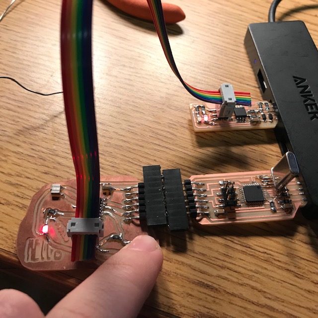
Here's a photo of the FabFTDI plugged in with my FabISP programmer. You may notice that I have pins coming off of the end of FTDI board instead of, I guess, holes? Anyways, this is because I didn't check which kinds of female headers we had stocked in the shop before I cut the design, and it happens that the male header fits better (or at least prettier). So I made a junky adapter to go between the FabFTDI and the target board, which you can see in the below picture, where I have one of my Hello World boards plugged in (upside down, actually, but it didn't matter b/c of symmetry of where the power is coming from, I think), re-programmed with a variation of the push-button-and-blink program from a few works ago.
Good things that I learned from making that board is that for USB purposes with this microcontroller (ATmega16U2)(neat note: allegedly this is what Arduino UNOs use for their USB conversions) you need either an 8MHz or a 16MHz external crystal resonator. The internal 8MHz resonator isn't accurate enough for high-speed USB. This is because you need 48MHz at 0.25% tolerance in order to use the 12Mbits/s USB, and the internal resonator has a tolerance of 0.5%. We didn't have a surface mount 16MHz crystal, so I soldered on a non-surface mount component, which looks kind of comically large. A good resource for this, aside from the previously linked FabFTDI board is this 2014 HTM(A)A page.
Aside from that, I made 3-ish boards this week.
The first board was a I'm-not-in-the-shop-but-I-have-a-phototransistor-let's-see-if-this-works board. I have/had a board from a few weeks ago that is non-functional because I accidentally ripped up a bunch of the traces. So, I removed some parts from it, added in wires, and wired up what is basically this board . I then loaded up Neil's light reflection synchronous detection hello world program. (side note: I don't quite get what synchronous detection is). Something that I've realized is that I've only been able to get red and green LEDs to light up and not the blue ones :(. This is because the blue ones need more power (you can kind of intuit this from the wavelengths of the different colors, but apparently it's a bit more complex than just that). The smallest resistor values I had on hand were 499ohm, and apparently that's still too large. I couldn't get the LED to light up until I swapped it out for a red. ):
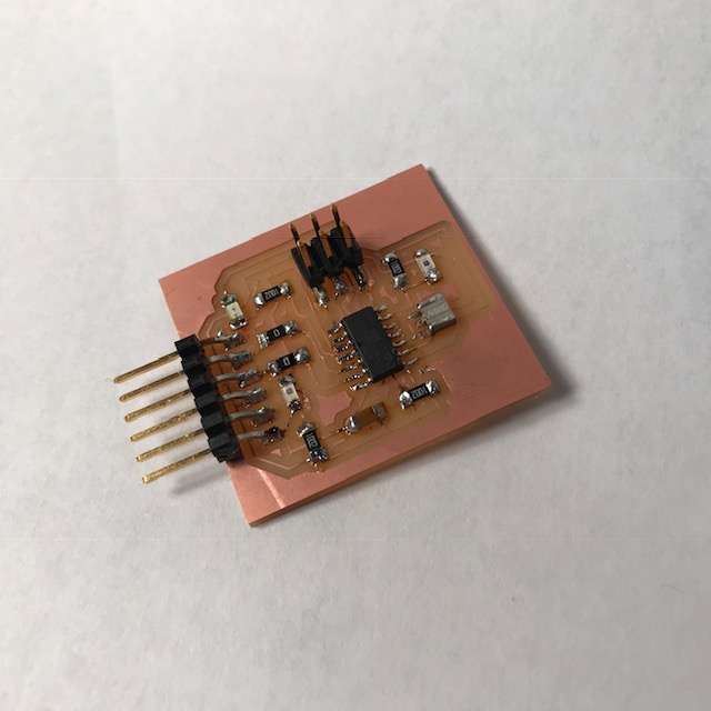
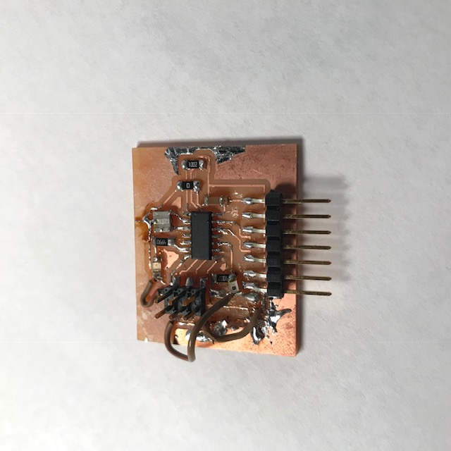
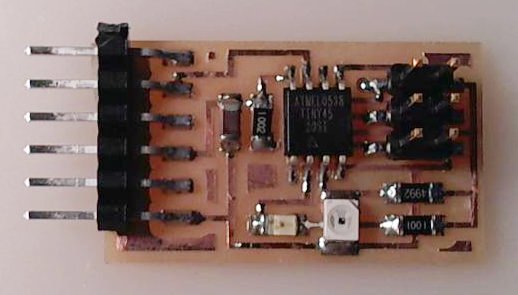
The next board I made was actually designed. It has two phototransistors and an LED. I also milled the already existing phototransistor board design (Neil's), in case this one didn't work, just so I'd have something reasonable to test code on. Neil's board is his asynchronous detection board. This one works off of looking at the reflection of light from the red LED, which is kind of like a hardware strategy of dealing with background light levels. (so this set up makes sense if you're trying to get reliable data of nearby behaviors, regardless of the ambient. My boards are not set up for this kind of sensing.
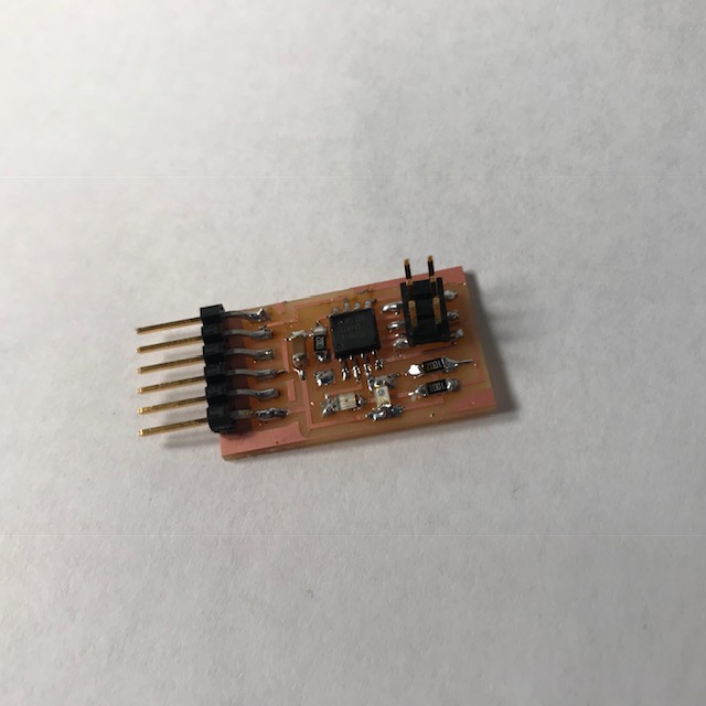
But, both the boards work, sort of. I can read something in from the phototransistors and then based off that value get the LED to do something, but I haven't been able to just get a serial display of the values coming off of the phototransistors yet :(