Week 10 - Output Devices
Notes
- Have to be safe
- Power supply
- Measure current
- PWM (Pulse Width Modulation)
- RGB LED
- LED array (CharlieComplexing) N pin for N(N-1) LED array
- LCD (Datasheet is only 2 page, which tell what are the pins) In the C code, there’s PROGMEM store the string in the flash instead of RAM. LCD_init() is start the comunication
- OLED used to be 100 dollar, is comming less than $10
- Video output (RS170 NTSC) have to have exactly timing.
- Speaker
- MOSFET (Gonna love) digital switch, need a resistor to protect
- Hardware PWM register: OCR0B
-
The output can be 0V , 5V, disconnected.
- Motors
- DC motor: key part(H bridge)
- Servo motor: 1-2 ms PWM to control angle (it consists of DC motor, encoder and control circuit)
- BLDC (Brushless DC motor) There’re triple-bridge. The driver’s power is propotional to Amp of the motor.
- Step motor (two sets of coil) Need two H-bridge. usually 1.8 deg per step
- Ac power Hocky Pucket
- Inflatable
- Pneumatically
- Hydrallic
Micro-controller max-current ~15mA
TODO
- Arduino output Black & White to AV (TVout)
- ATtiny44 generic pin
- ATtiny44 video output
- Arduino output LCD
- Arduino output OLED
- ATmega generic pin (next week)
TVout
Links
Problems
How to connect GND to RCA connector’s yellow (composite video) plug?
The RCA (derives from Radio Corporation of America) connector usually has 3 wires (sometimes 2 wires, video & audio). Yellow is composite video. And the white and red is for stereo audio (left & right).
By using the multimeter, it turns out the yellow wire is like this:
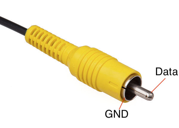
All the other-color wires have the same configuration.
Why using 1k & 470 Ohm resistors?
The VCC is 5V, then why using 1k & 470 Ohm to generate 0.3 - 1 V DAC output?
After searching in the Google, it turns out most of the TV’s AV input has a 75 Ohm resistor between Vid and GND. link
So using 1k will generate: 5*75/(75+1000)=0.348 V output. (Black)
using 470 V will generate: 5*75/(75+470)=0.688 V output. (Gray)
using 1k & 470 (in parellel) will generate: 5*75/(75+(470*1000/(470+1000)))=0.95 V output. (White)
What’s J2 power, IC2 in Neil’s board?
J1/J2/J3 is generic header like link.
In Neil’s CAD, the IC2 is a regulator (LM3480IM3-5.0/NOPBCT-ND), convert the voltage to 5V.
Due to the datasheet, it can convert up to 30V input voltage to 5V output.
What’s SPI? How to use I2C?
Tutorial on basics of I2C and SPI.
How to use external ADC (To speed up the reading of analog video input)?
Do I need external resistor/capacitor?
Tutorial on how to use external 12-bit SPI ADC (MCP3204).
For color image input, how to read phase & intensity?
What’s the frame rate of ATtiny44 video output?
60 Hz.
What’s the speed of PORTA?
Clue: Oscilloscpe says ~1 us for PORTA = pattern[col++];
What’s the computation difference between ATtiny vs ATmega vs ATxmega?
TVout test demo
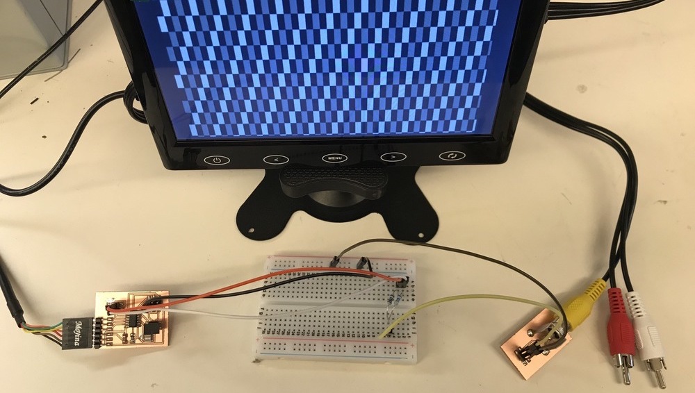
I ordered an small 7” monitor on Amazon (link) with AV (Analog Video) input.
To test the funcionality of the monitor. I tested the TVout library for arduino. Since I don’t have the 470 Ohms at home, I used (220+220) Ohms to replace. It will make the image brighter which is totally acceptable. It works perfectly! Very exciting!
ATtiny video output
I made a generic ATtiny44 with PA2/PA3/PA7 output. It has 2x2 pin hearder so that I could connect it to the breadboard.
Also there’re RCA jacks in the EECS shop, so that I made a small PCB board to connect the jack.
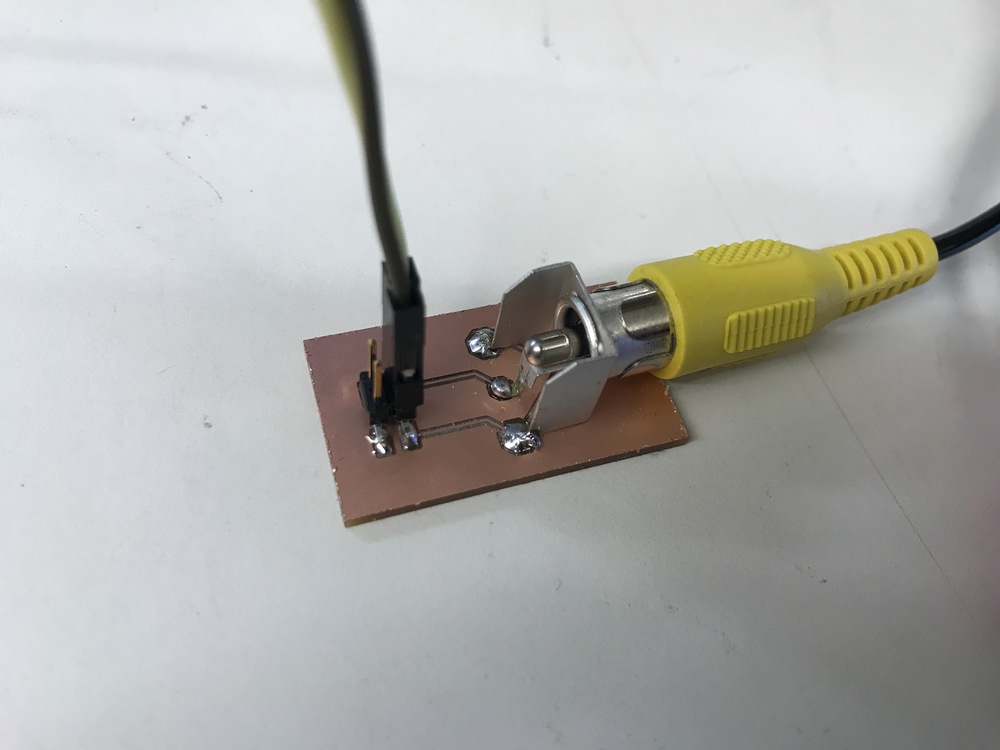
After soldering and connecting, I start to test the board.
Zack taught me how to use the oscilloscope! It very very exciting to see the singals with eyes.
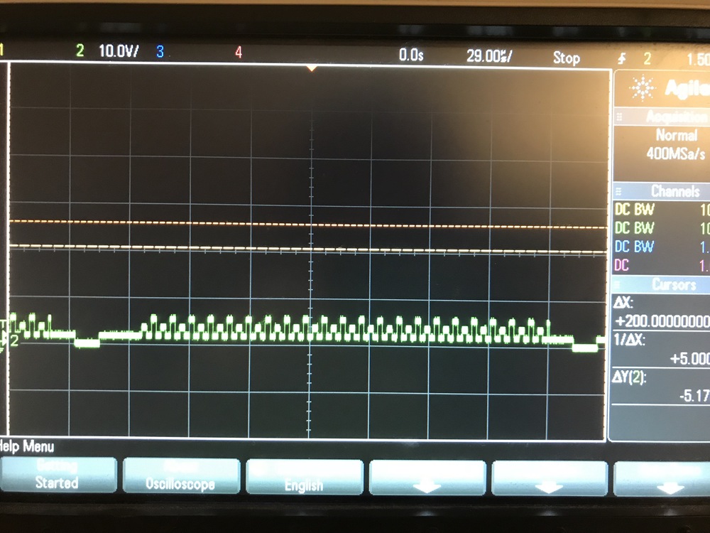
However, I ran into a problem, the duration of the sync & horizontal duration is not correct. I tried to change the value in the code to make it faster, but it doesn’t work well. So I posted on the gitlab issue:
Hi
Have someone tried the NTSC analog video output?
I used the ATtiny44 and was trying to run Neil's hello_video example code.
By using the oscilloscope, all the output value is correct (There're horizontal sync & vertical sync & black lines...). But the timing is too slow for NTSC standard. The sync should be 5 us but instead was 11 us. And the horizontal line should be 63.55 us but instead was 240 us.
I was using a 2x2 header for output pin and connect it to a breadboard for this experiment. Don't know whether this could be a problem? I test the breadboard on Arduino TVout and is working correctly.
Appreciate your help.
And Brian said
Did you remember to program the fuses? It sounds like you might still be running on the internal 8MHz oscillator rather than the 20MHz external resonator.
Ooooops.
Important: To use the external 20MHz clock, we have to run the program-avrisp2-fuses first.
I ran the program-avrisp2-fuses again, and it works!!!!
And to make the horizontal line to be 63.55 us, we have to change the end=87 + offset + (row / 20); in the do while. In my case, I change 87 to 49 and it’s perfect.
Upperbound: make it 52 will have some distortion on the first line. 53 wil not output any images.
Lowerbound: make it 47 will have some distortion on the first line. 46 will have no output.
Since each color change has a duration of ~1 us. I think the tolerance of line scanning is about 63.55 +/-2 us.