finalprojectfinal
-----------------------------------------------------------------------
project description
my final project goal is to build a chair that is “rigged” out. for a starter chair, i will be focusing on installing a thermal heating device to one of the armrests to act as a mug warmer to keep my seasonal hot chocolate beverage warm on cold, cambridge nights. i am also notoriously bad at drinking my beverages in a timely manner and my drinks get too cold to drink consistently. the warmer should be able to warm up a cold beverage automatically once a certain temperature has been reached.it is a chair meant to add additional lounging/seating area in my room with the added benefit of being able to place a drink on the armrest to keep warm on cold, winter nights.
- someone has installed a heating device into a vest
- someone has also put in a heating device into a table - my project has a different 3d design element and programming requirements for the heating element. i would also like a visual stimuli of when the drink is cold, warming, and hot.
i design everything from the chair to all of the electronics associated with heating the the mug. so the shape of the chair (initially it was supposed to be topology optimized, but due to some unexpected results for that computational analysis, it was not able to be performed this iteration).
| Material/Component | Price | Origin Reference |
|---|---|---|
| 4x8 3/4" plywood | $40 | n51 |
| Copper Vinyl | $0.01 | arch shop |
| copper board | $0.20 | arch shop |
| attiny84 | $1.48 | arch shop/digikey |
| (1) 1uF capacitor | $0.05 | arch shop/digikey |
| (5) 10k ohm resistors | $3.00 | arch shop/digikey |
| (2) 1k ohm resistors | $0.02 | arch shop/digikey |
| (1) 499 ohm resistors | $0.01 | arch shop/digikey |
| (1) 0 ohm resistors | $0.01 | arch shop/digikey |
| (1) thermistor | $2.50 | arch shop/digikey |
| (1) n-channel mosfet | $1.13 | arch shop/digikey |
| (1) LED RGB | $0.53 | arch shop/digikey |
| (6) 2x2 headers | $4.00 | arch shop/digikey |
| (1) 2x3 headers | $0.60 | arch shop/digikey |
| ceramic heating element | $4.00 | amazon |
| voltage/amp wall plugin | $11.00 | amazon |
the total cost for this chair is: $68.54
the majority of the cost comes from buying the plywood material as well as the wall -plugin.
the chair itself, the mug holding disk, and all of the electronics boards
the processes used include: milling on the SRM-20 (electronics boards), milling on the C.R. Onsrund (chair pieces), 2d designing each of these elements, electronics design/production/programming
how do armrests fit into a chair design? what are the necessary volts and amperes needed to properly heat up a drink? what happens when a mosfet that is too small is placed on a board producing a lot of heat? is it safe to have a heated mug on a armrest?
the construction of the chair (did all the pieces fit together? is it what i imagined the 2d design to be in 3d?), does the heating element work to get the drink hot? does the heating element turn on automatically when the drink needs heating?
warm drinks everywhere!also greater understanding of translating thermistor temperatures and understanding how volts and amps play a role in heating elements
3d design
the design of the chair was a combination of being inspired by the lawn chairs scattered around MIT campus, a concept i had in my head, as well as an attempt to create a cozy armchair (out of wood (cushions to be added later). the process of designing included first creating a 3d model of the chair in rhino. i learned from the “make something big week” that going from 2d to 3d is a little harder than going from 3d to 2d, though it still has its limitations. the 2d to 3d transfer is difficult because it is difficult to visualize the pieces together and easy to get angles and pieces slightly not the right size. 3d to 2d is difficult, because once the 3d model is deconstructed and laid flat on the template size, it could be a super hard game of tetris to get everything to fit. my initial design had to be modified to be able to fit on the 4x8’ piece of plywood.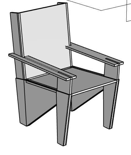

with my rhino file complete, i made sure to assign the different groupings for points, cutouts, and pockets. with some help from the shop tech in n51, i created a mastercam file for the milling process.
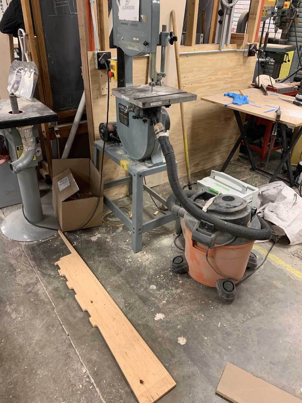
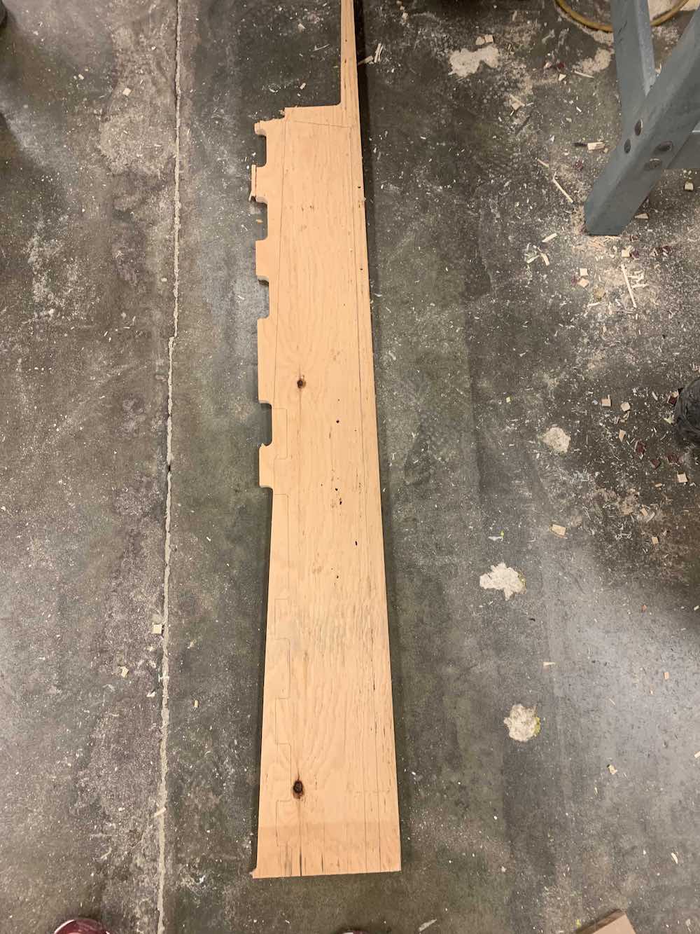
the milling process itself came with several complications. the first of which was that i was misguided in the tool that should have been selected for the milling of the cutouts (they had told me to use a 1/2” short flat, but that just started to rip up my plywood — a quick stop to the milling had to be done), and there was a problem where for some reason my milling lines were at an edge where after milling a section, it disconnected from the bigger 4x8’ piece but moved everything slightly.. (so everything on my milled pieces were slightly offset and needed a lot of post-processing). this also caused an entire piece of chair to just not be milled (because where it was supposed to be milled had been detached from the larger 4x8 — so that had to be done manually afterwards. the biggest challenge for that was the press fit joints — the bandsaw didn’t have the clearance/diameter to achieve those, so a different square drilling tool was used. see pictures below of these occurrences.
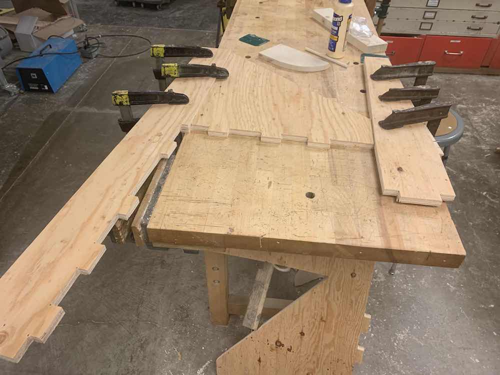
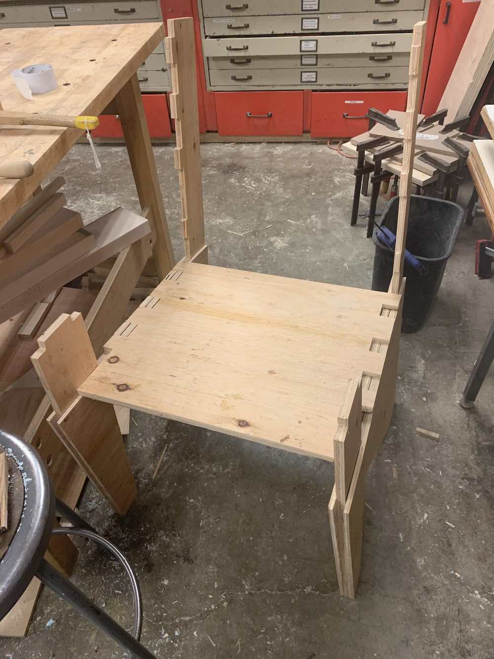
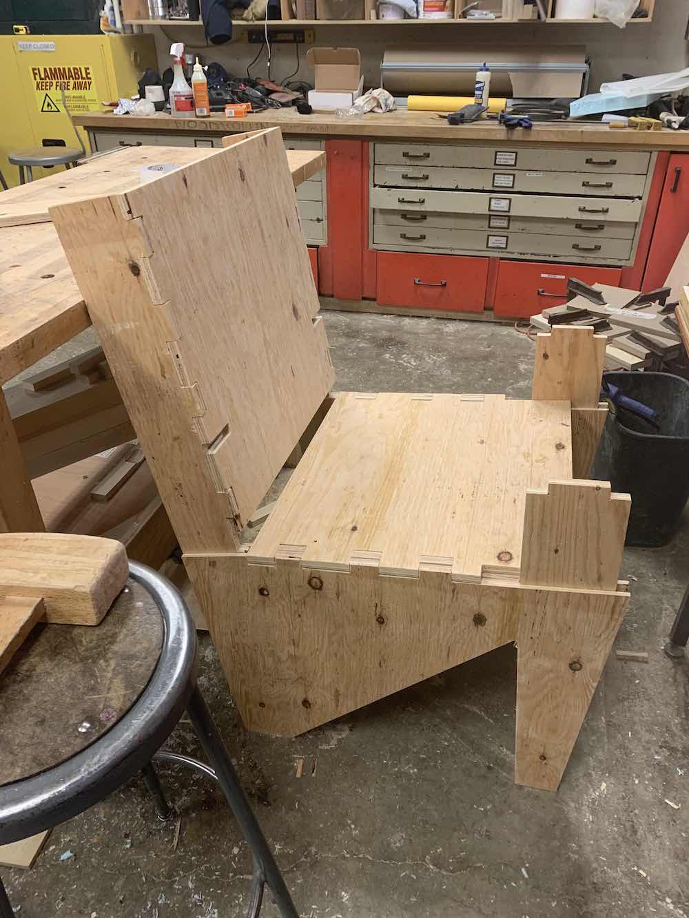
eventually, i could crack along trying to fit my chair together. i had a good tight fit on my press fit joints. glued together the legs where the pockets would envelop each leg in the front and back. and we had a chair! (much more post-processing was involved aka cleaning up the press fit joints and sanding, etc).
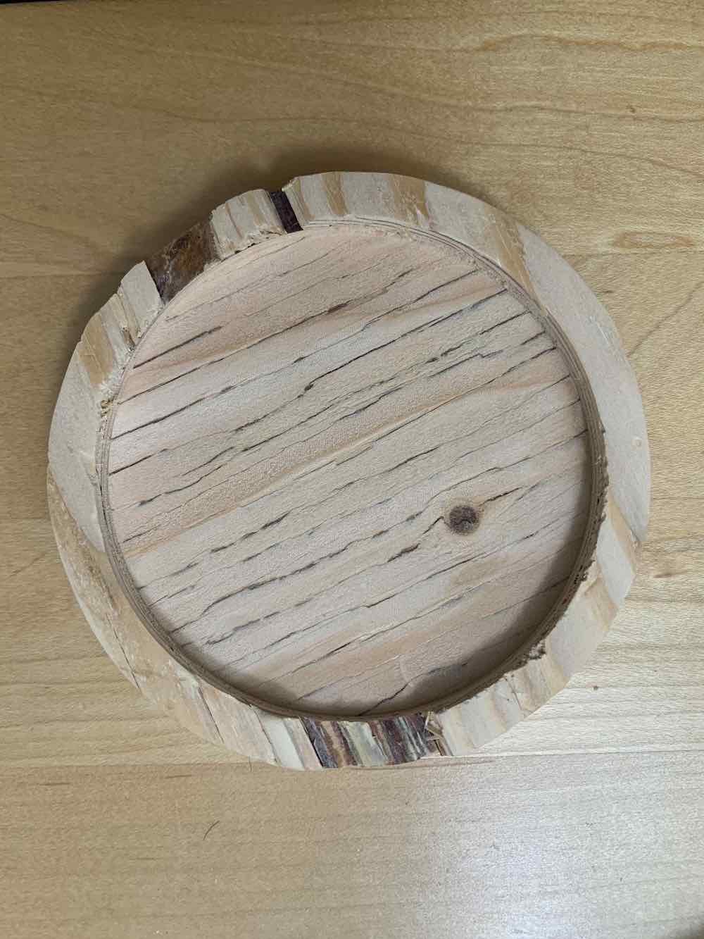
i also milled out the elements that would house my mug warmer. a circular disk with a pocket to hold the electronics.
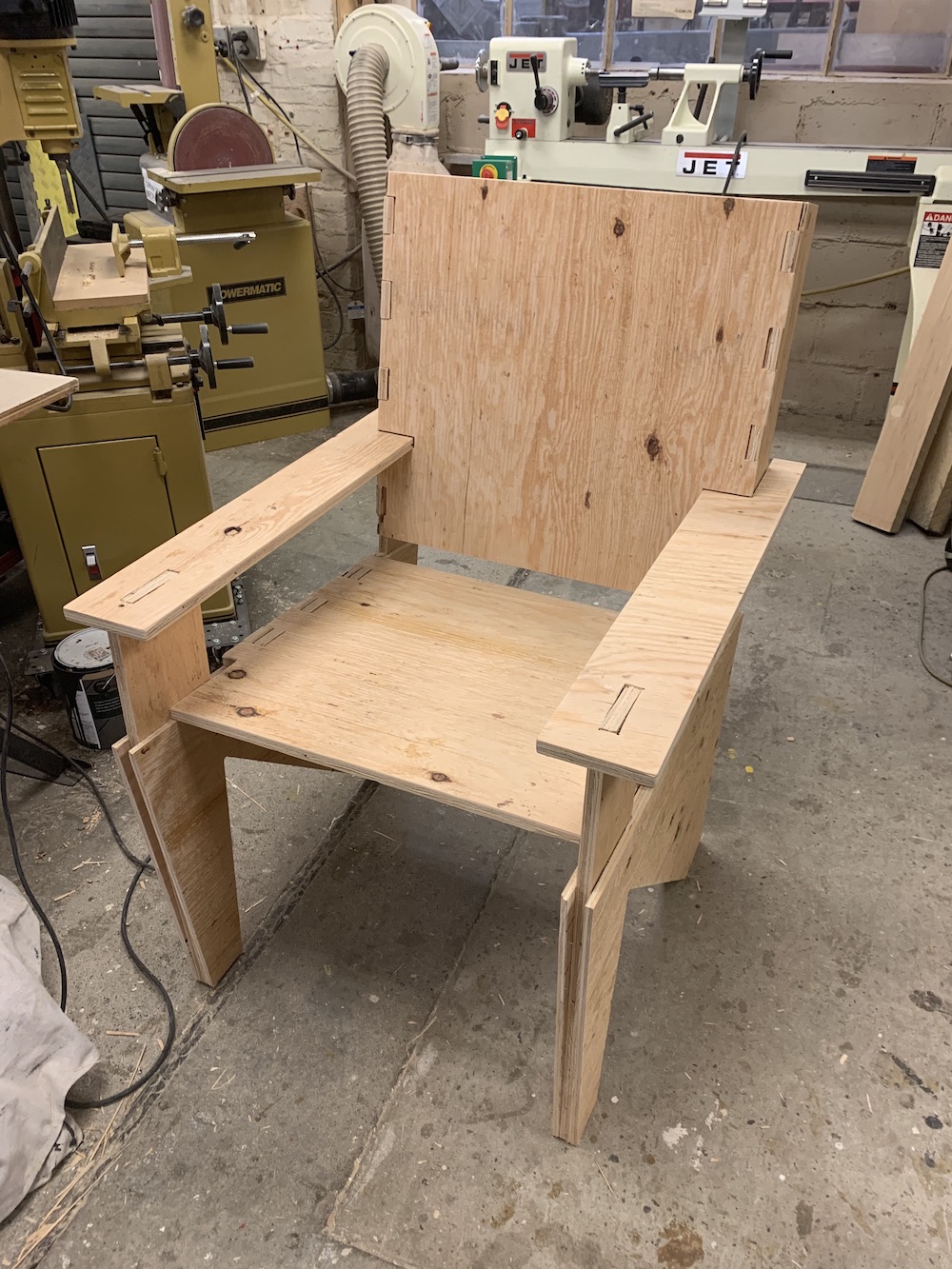
the chair was slightly.. larger than expected.. but i really like it!! i feel throne-like and once i add cushions, it’s going to be such a cozy reading chair, with the correct angles that align to my favorite book-reading posture (not to worry, the armrests are parallel to the ground).

electronics
the electronics design has gone through several different iterations forthe electronics portion of the final project i have been working on for weeks — trying to use each of the weekly assignments to make progress, but mainly in the last two weeks trying to get ahead by making prototypes of my final board and debugging problems. this turned out to be a great strategy, because, boy, i had a lot to debug.
iteration 1:
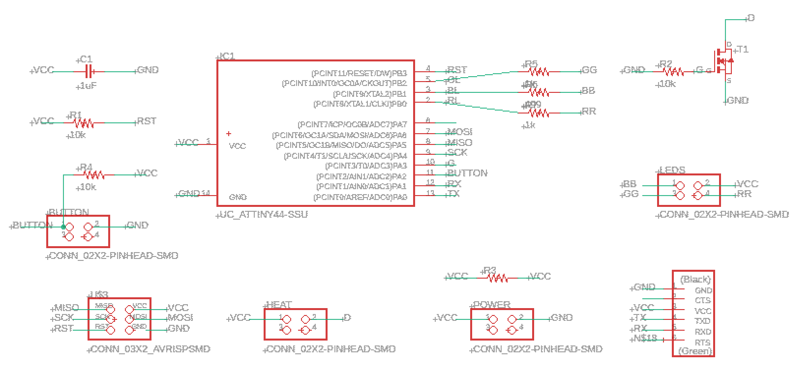
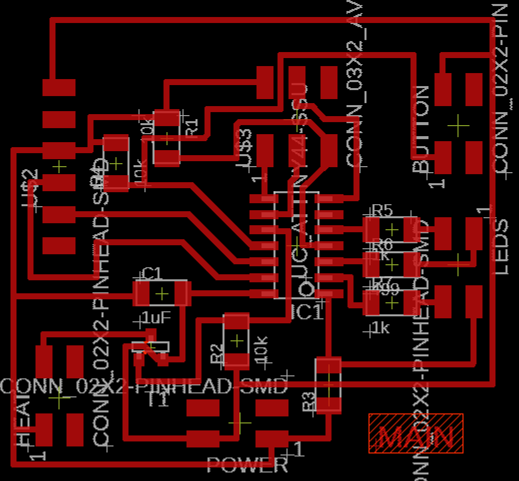
main board:

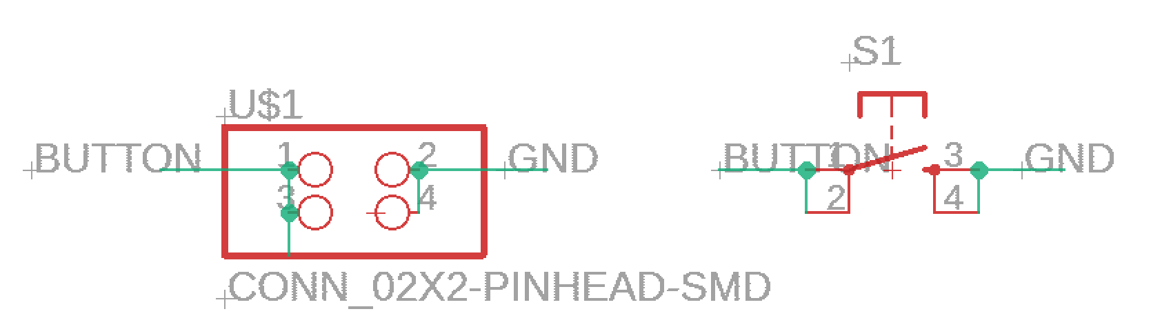
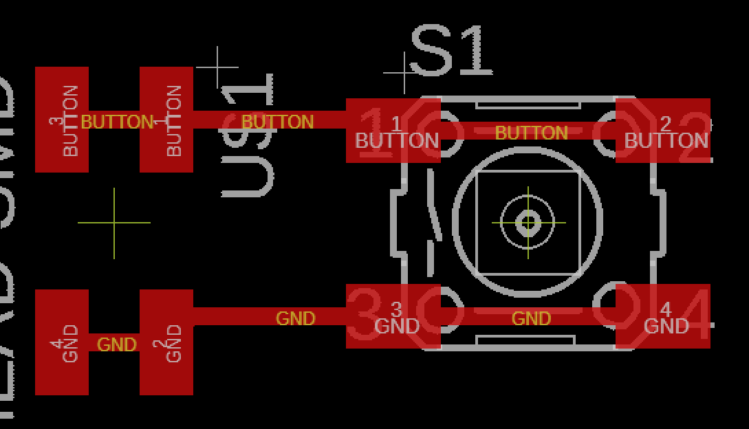
button board:
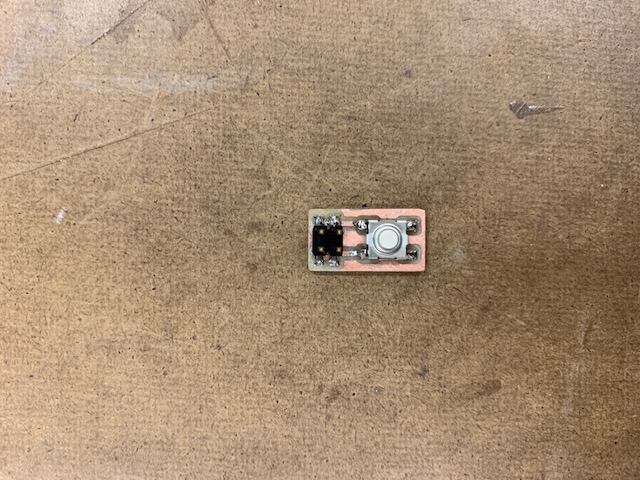
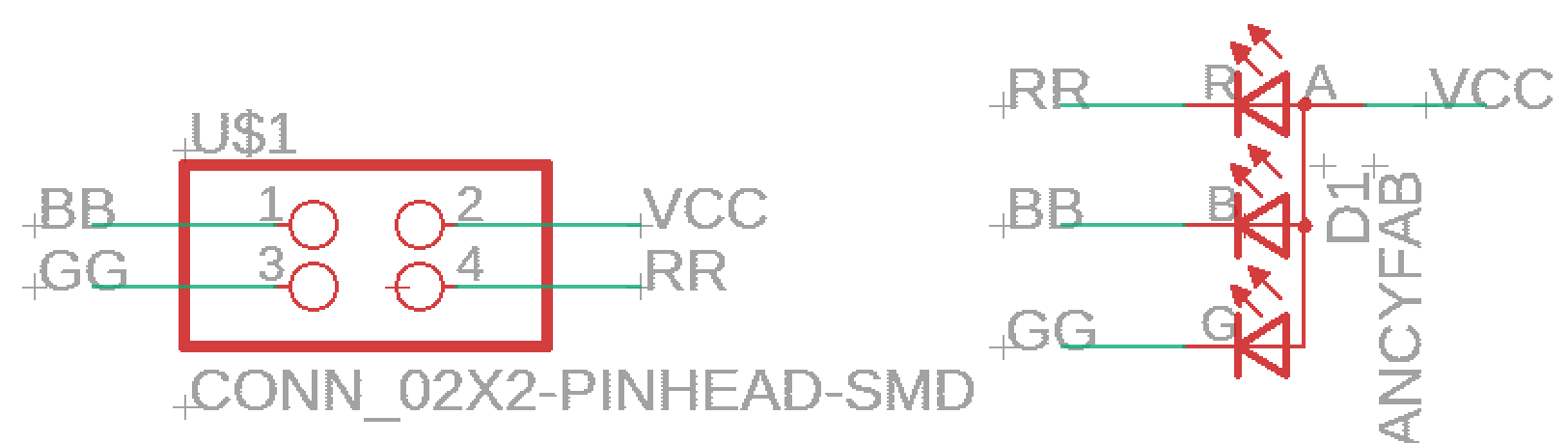
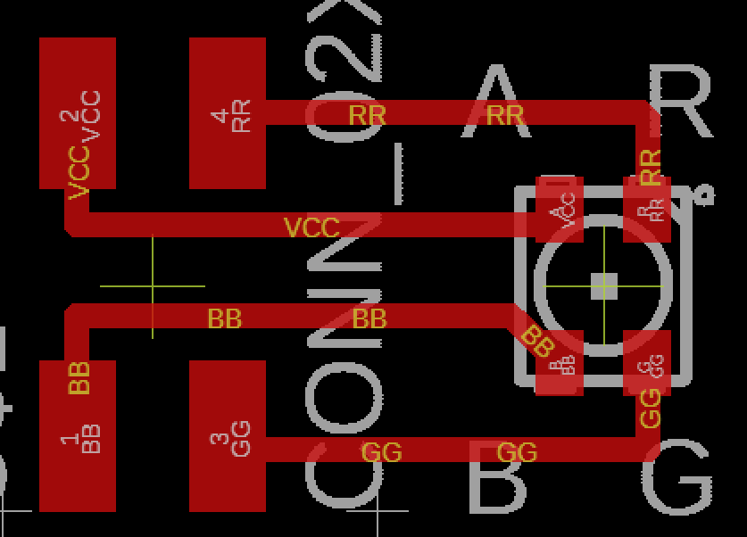
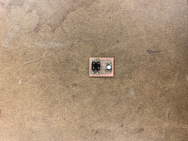
led board:
power board:
after it was milled and soldered, i attempted to program the board. first, i wanted the button and RGB led to work, because i've done that before, and wanted to make sure my board worked in general -- and success! the goal of this board was to try to get the heating element to work. his is where all the problems/solutions happened. on the board, i installed a mosfet to act as a switch to the heating element. i wanted to be able to call on the pin to only turn on the heating element when my button was pressed.
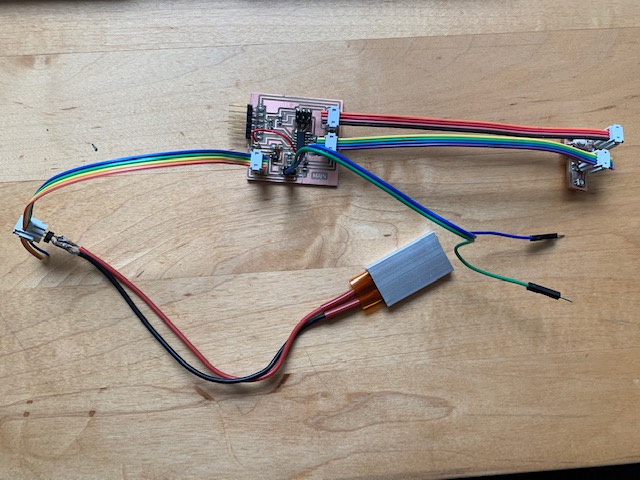
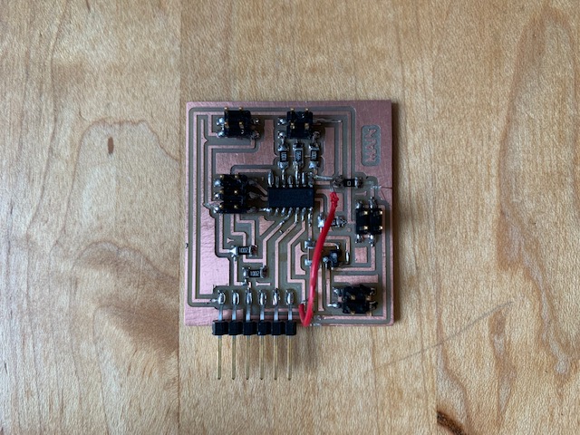
the first iteration of problems was that my heat element was designed for 12v while the microcontroller is only designed for 5v. plugging in the external power source at 12v to the board fried my attiny44 -- had to be replaced and redesigned. just to continue testing purposes, i replaced the attiny44, and broke the voltage connection between the heating element, external power source, and the rest of the board. this should have worked, but not enough amps were getting to my heating element. this i learned, was due to the incorrect mosfet being used. during testing with a voltmeter, when the mosfet was being bypassed, the heating element would heat up!! the mosfet i was using didn't have the amount of amps available to send the 3-4 amps of current needed for the heating element to get as hot as i needed it to be. the external power source was still plugged in, and my mosfet eventually burned -- a little scary honestly. a bit of the burned mosfet can be seen in the picure above (in the middle underneath the red wire).
the next step is to re-mill the board with the power source detached, the correct traces, and add a thermistor. testing of the thermistor has already been conducted in previous weeks, so hopefully not too much will have to be done. I do remember almost having an issue of memory when programming the thermistor using Arduino, so maybe I will also upgrade to an attiny84.
iteration 2:
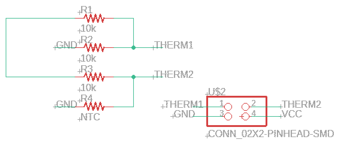
in the second iteration i wanted to combine the implementation of the thermistor, led, heating element, and external power source. i upgraded to an attain84 due to some previous memory limitations i was coming across in week 8: inputs, when i was working with the thermistor. the goal was to get the thermistor to read temperatures and automatically turn the led either blue or green and turn the heating element off or on (through the mosfet switch).
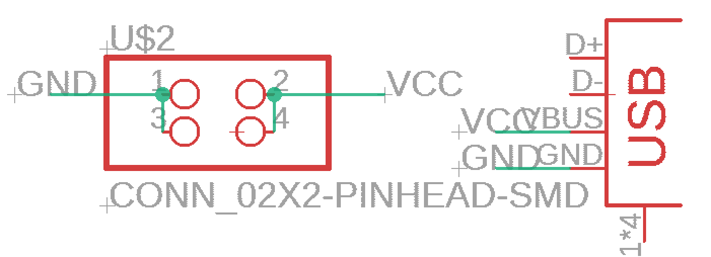
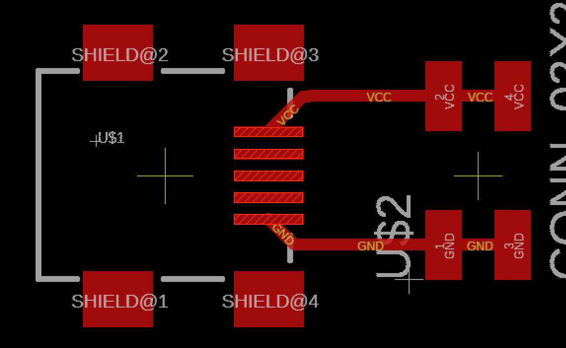
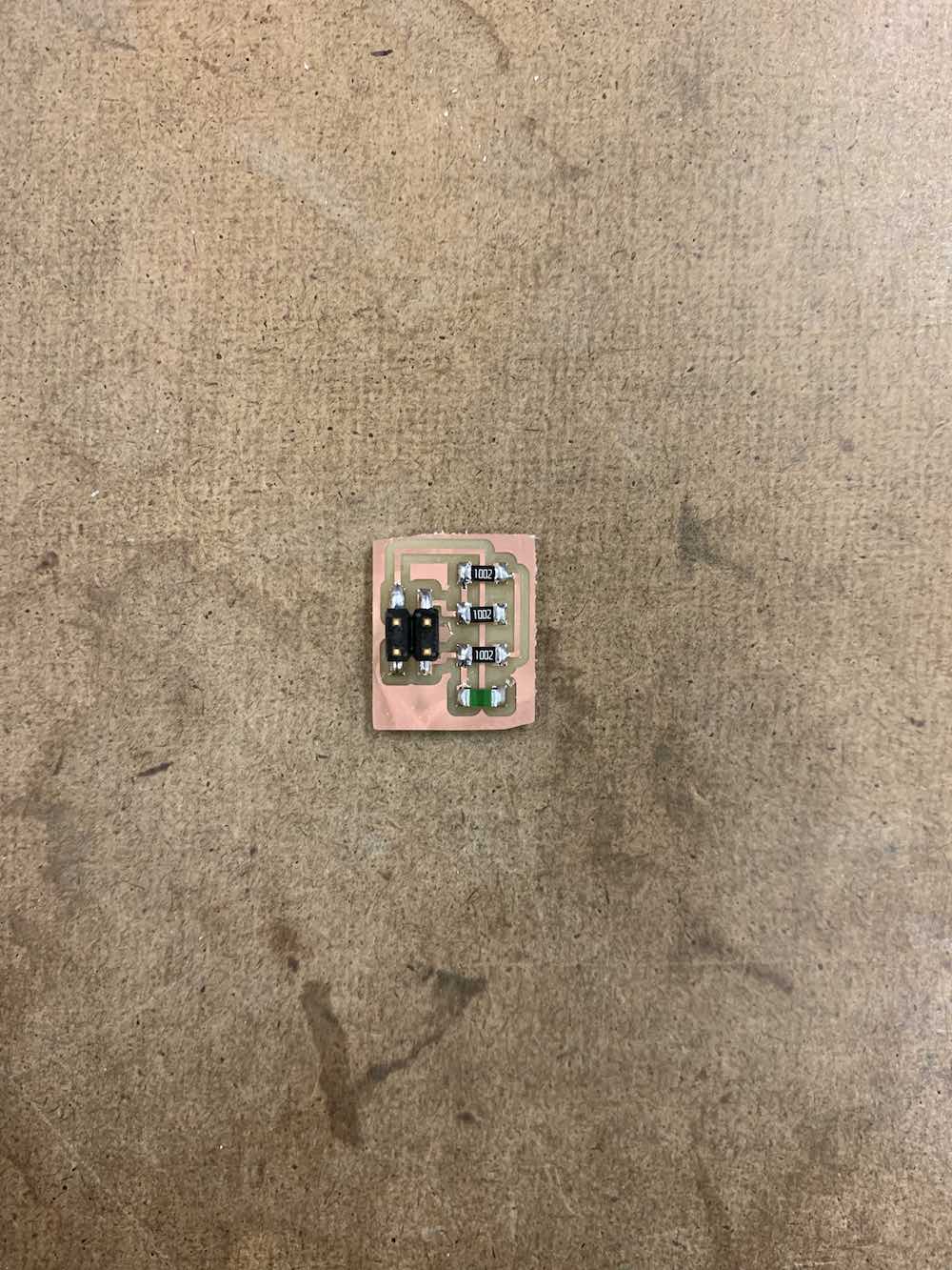
the thermistor, led, heating element, and power source were all connected to the main board using 2x2 pin headers.
main board:
led board:
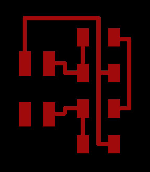
themistor board:
heating element:

power source:
programming
i used arduino to program my board. the code used to program it is shown below (there were several different testing iterations before this one that was able to get results).
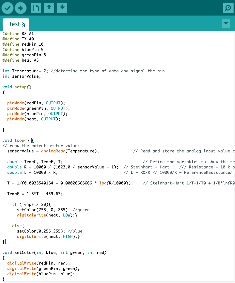
the code is essentially asking to get a read on the thermistor, get a temperature value (which was tested in the input devices week, but i was having some problems with this initially, but i was calling a wrong pin that eventually solved my problems), and then based on whether the temperature value was above or below room temperature, it would automatically turn on the heating element and change the led color.
some things that i learned in the two different iterations in trying to get heat is that in the first iteration, i had the heating element connected to the 5v source ftdi from the computer — this resulted in very little heating. looking back at the amazon details of the product, the heating element actually needed 28 w of power, which translated to 12 volts and 2-3 amperes depending on how hot i wanted my drink to get. the next think i learned was about the mosfet. i was initially under the impression that the values describing the mosfet were in relation to the amount of voltage that was going into the mosfet (so in my first iteration, i was assuming 5v coming from my computer), but in actuality, it is the amount of volts and amps it is able to hold without getting too hot (learned that the hard way).
the way in which the heating element is programmed is that if the temperature is less than 120 degrees, then the heating element will turn on to warm the drink, otherwise, the heating element will turn off when warmed. my room temperature wavers around 70 degrees, and the heating element remains hot for several minutes before cooling, so the degree difference is enough to keep the drink warm. I didn't want to make the allowable temperature higher, due to safety concerns.
final project
reflection
overall, i think my final project was a success! I was able to create a sturdy chair where i’ll be able to lounge in my room with a good book — and now a hot beverage. the side element of the heater is actually able to warm my beverage!! (re: the surprised look on my face — the real reaction — of my warm drink after being on the warming element).
I do think in future iterations, i will work on a better execution of the assembly as well as more pizazz in the light show occurring when the drink gets cold and hot.