Computer-Controlled Cutting
Press-fit construction kit
Concept
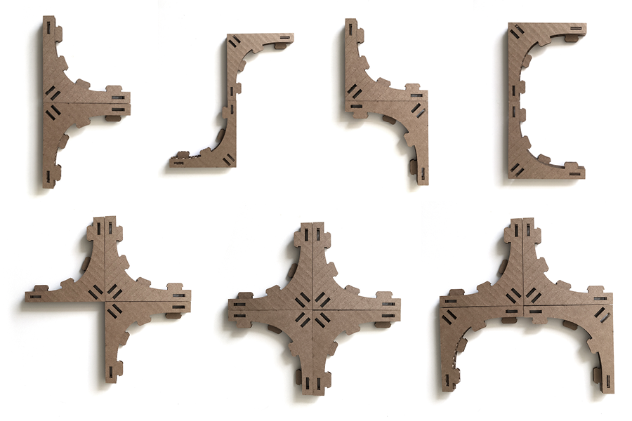
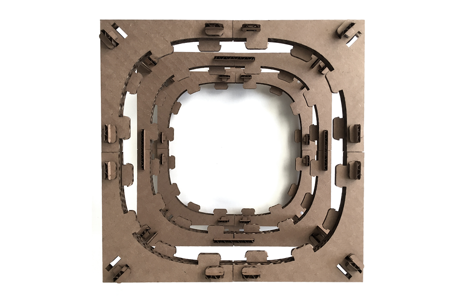
Here I was interested in making a construction kit for a simple, reconfigurable stressed skin structure. The kit contains parts for building a frame, and then covering it with a curved surface. The main L-shaped module can be attached to itself in various different ways, enabled by the different types of plate connectors that attach to either the corners or ends of the module.
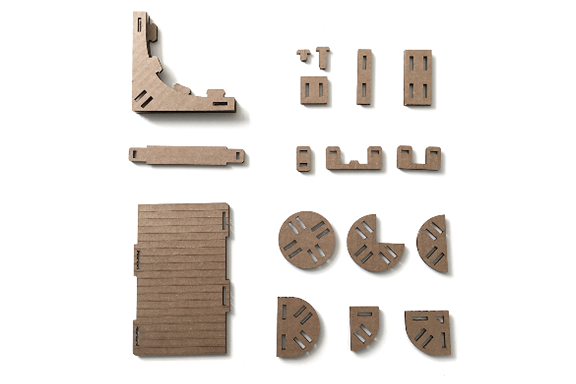
Assembly
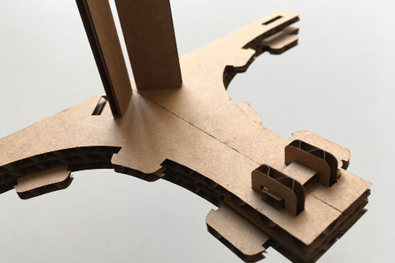
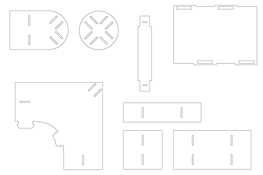
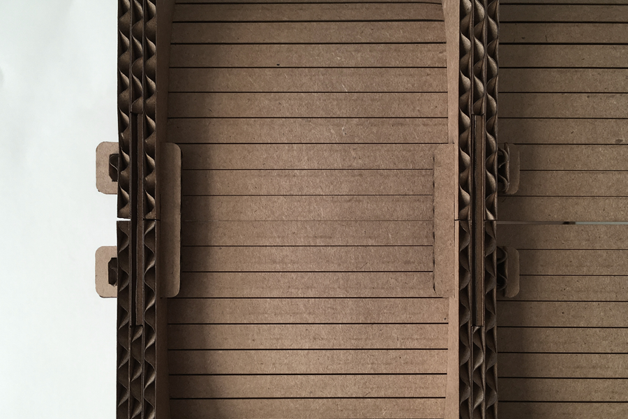
The L-shaped module is made from three laminated layers of cardboard, where the center layer has hollow areas that allow space for a plate connector. Here you can see different connection variations that the kit allows, plus the plate connector that slips between the outer layers of the modules.
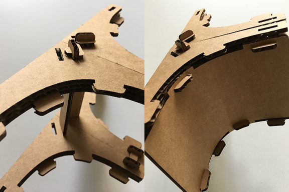
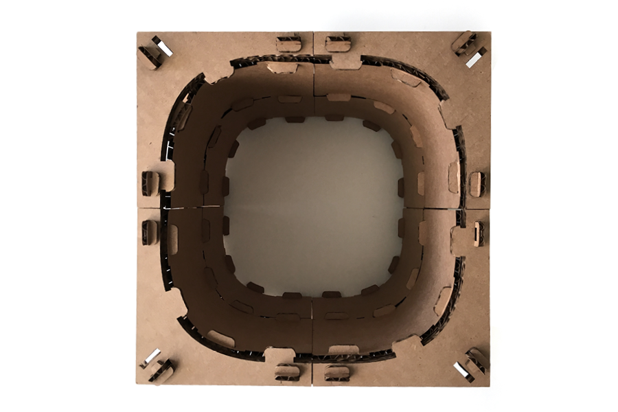
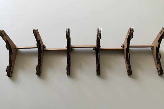
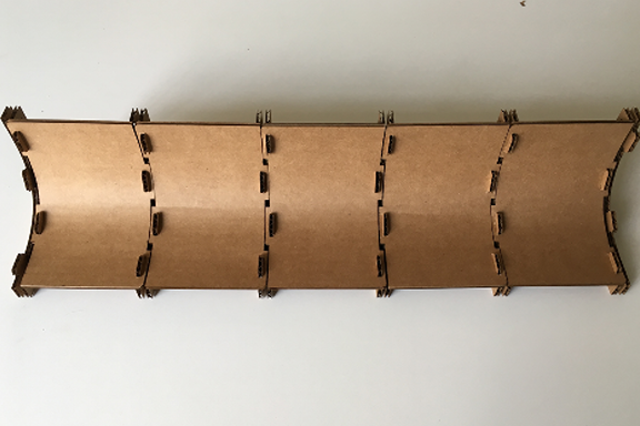
After the L-modules are connected in the desired orientation, these attach to a rib connector that hooks two layers of L-modules together. This constitutes the simple frame that is then covered with a skin panel. The skin panel stiffens the frame, and is scored on one side to allow curvature.
Parametric Drawing
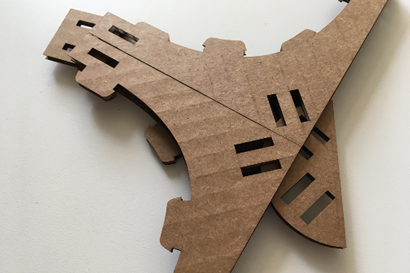
The part shapes are generated from a number of parameters, primarily driven by the material thickness, L-module size, and radius of the circular plate connectors. The entire assembly system is based on a generic pin connection detail that is applied to every location where a rib member connects to any of the L-shaped modules.
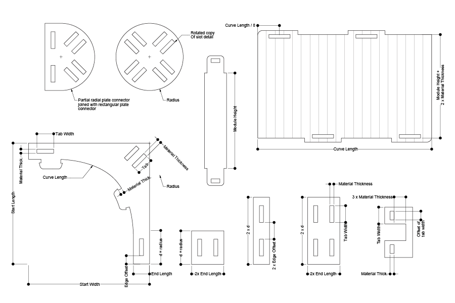
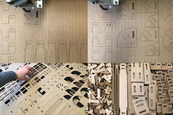
Tolerance and Material Orientation
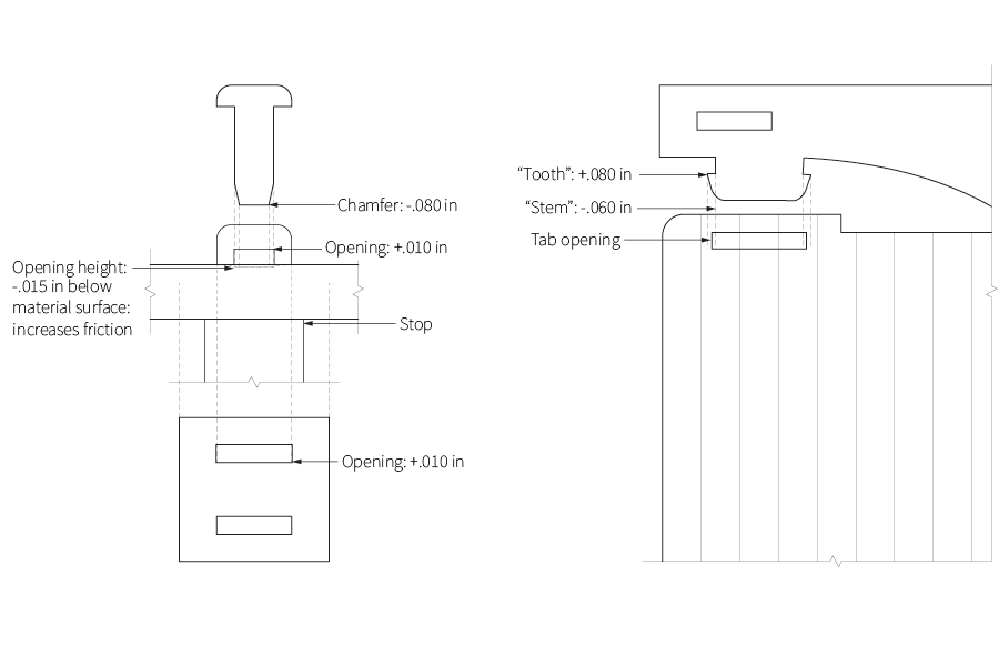
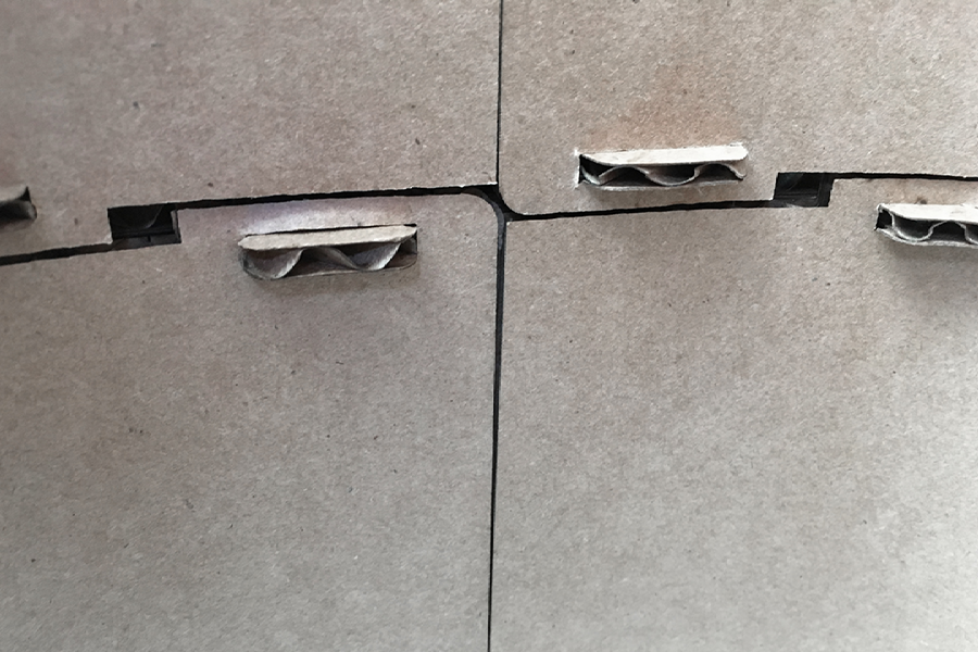
In the cutting process, most of the tolerances in the connection detail are made to help the assembly process be somewhat loose, with the exception of the opening that receives the pin. This slot is lowered by .010in to create some friction between the pin, the stop, and the outer surface of the laminated cardboard assembly. The orientation of the parts on the cardboard sheet was also important, since this allowed for greater strength in the L-shaped module. Other parts, such as the pins, tabs, and skin, also required a specific orientation on the cardboard.
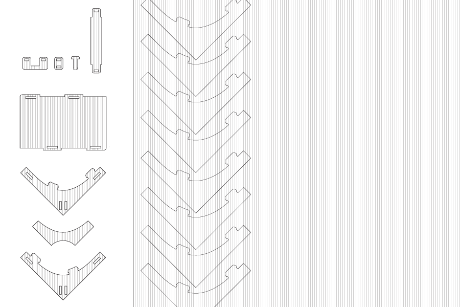
Variation
The kit can be assembled multiple ways, two of which are demonstrated here. In both assembly types, the frame is assembled first, then the skin is added all at once in the final step. The result is a fairly rigid assembly.
Detail
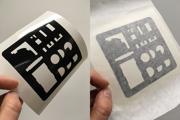
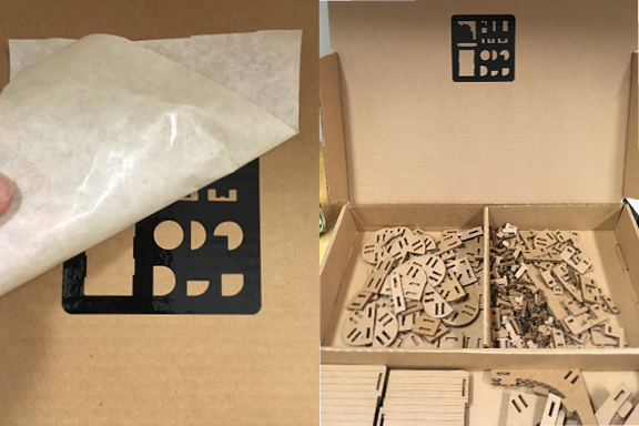
Vinyl Cutting
On the vinyl cutter, I made a simple diagram of the part shapes that are contained in the construction kit. If I repeated this, I would take care to weed the details on the adhesive paper rather than on the original vinyl; I intended for there to be more detail here.