Electronics Design
Designing the Circuit
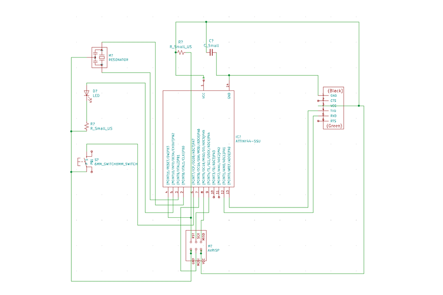
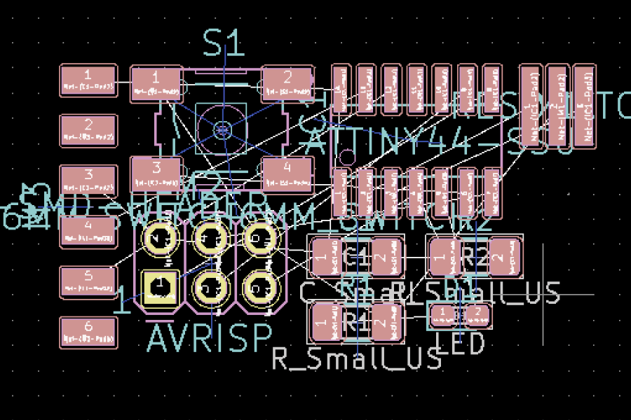
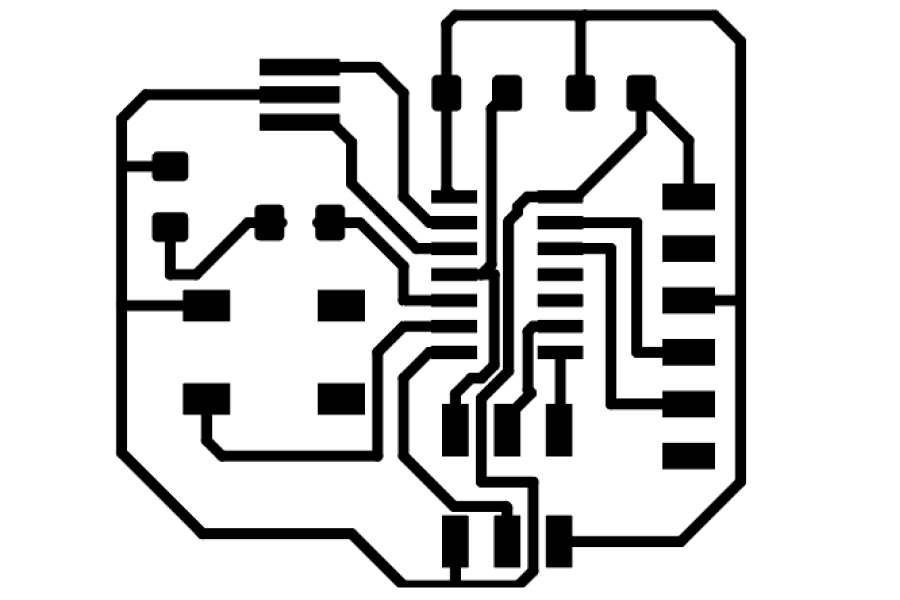
This week I used KiCad to design a circuit based on the given schematic, to which I added a button and and LED. Since I am still very new to electronics, I kept this a simple as possible while I tried to absorb the new process. After importing the Fab library into KiCad, I used this to generate footprints for fabricating the circuit.
Making the Circuit
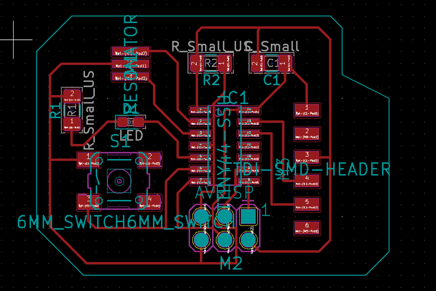
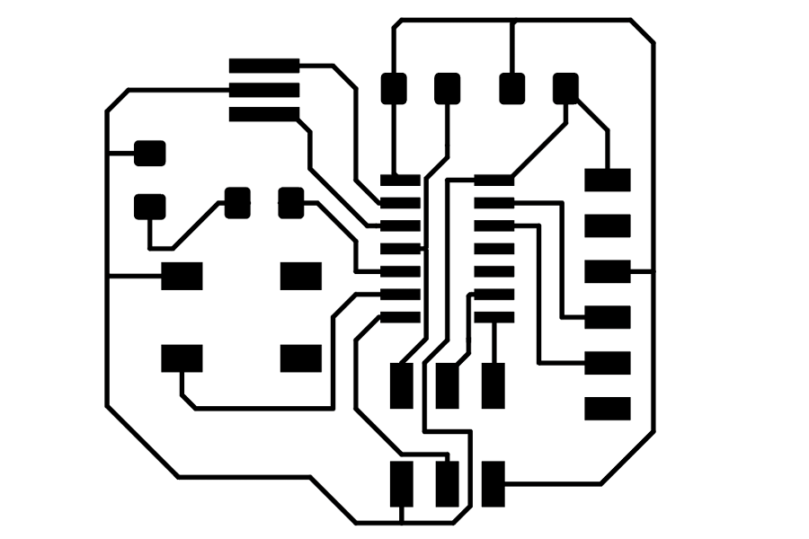
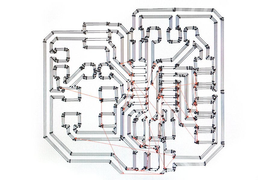
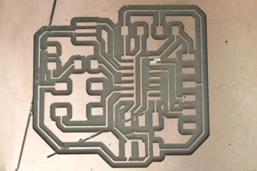
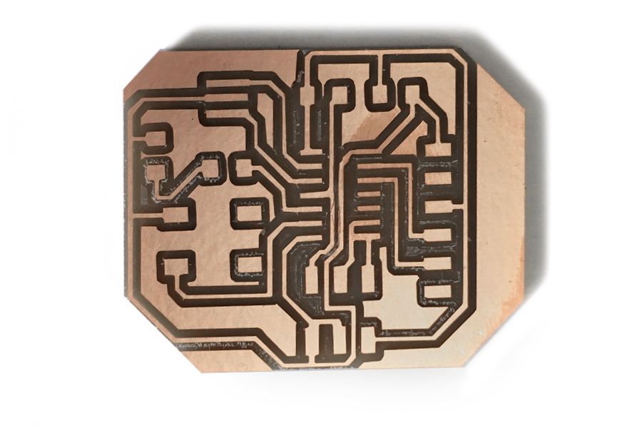
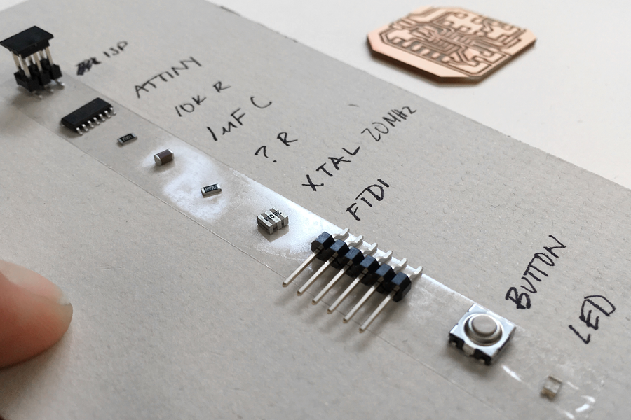
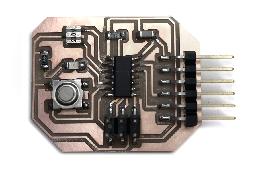
I milled a first version of the board, but discovered that the width of my traces was probably too thin. In fact, some of the traces appeared to be broken, or milled all the way through. I did a second pass in KiCad, changing the design rules for the with of the traces. The updated file milled properly. Similar to last time, I organized all of my components and soldered them to my board.
Programming
When I arrived at the programming step where I planned to the Arduino interface, I realized there were problems with my board. The setup initially appeared successful, but then there was a failure in the communication of the devices. Using help from the TA and a multimeter, I discovered there were a couple of shorts on my circuit, where the elbows of the ISP were accidentally touching the traces that run underneath.
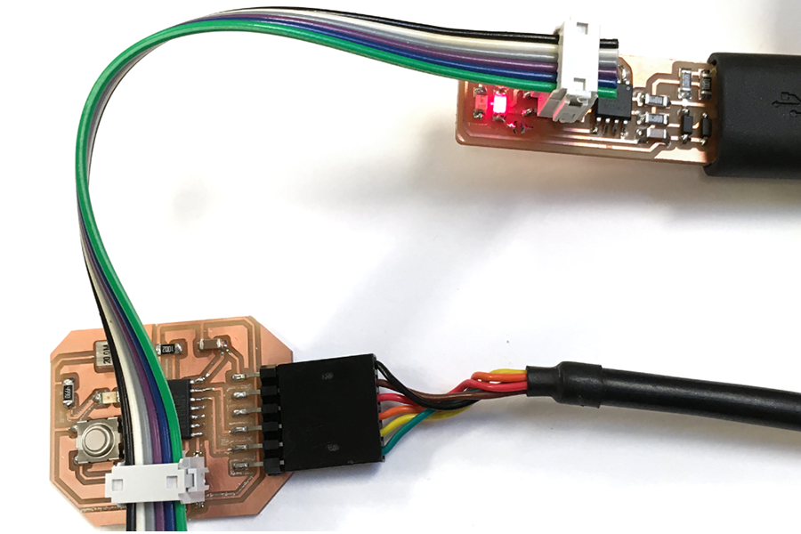
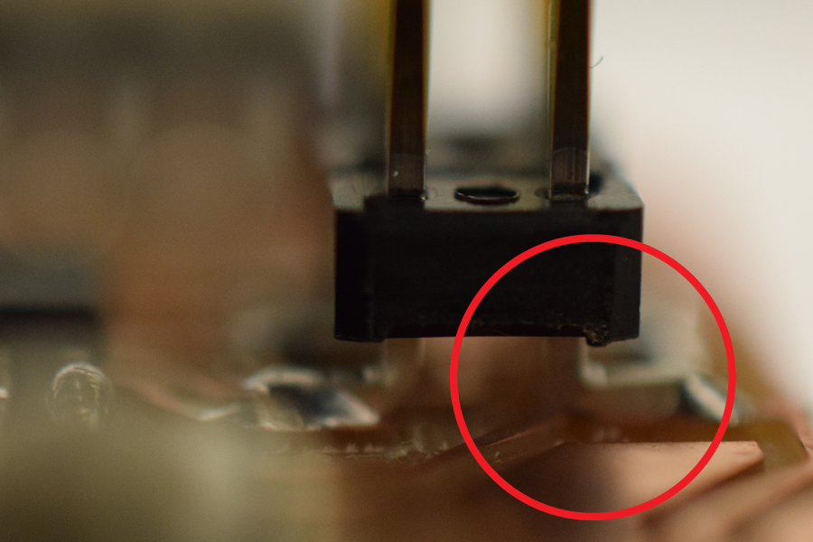
In the next steps, I will remove the ISP and reattach it, hopefully fixing the shorts and successfully programming the board.
