
Embedded Programming
Troubleshooting
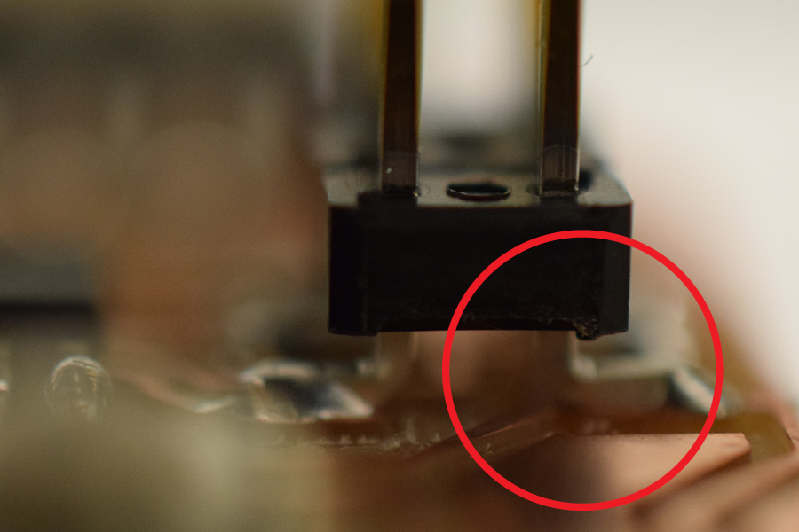
This week I picked up where I left off at the end of electronics design week with continuing to troubleshoot whatever had gone wrong when I was building my circuit board. Initially, I thought the problem was limited to just one short caused by the elbow of the 2x3 header touching one of its nearby traces.
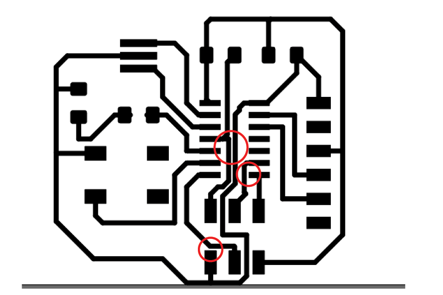
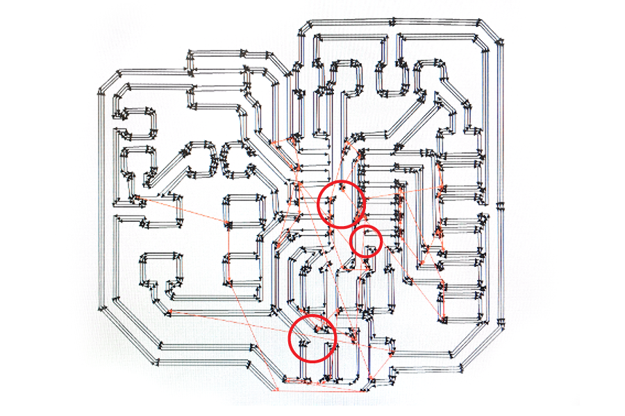
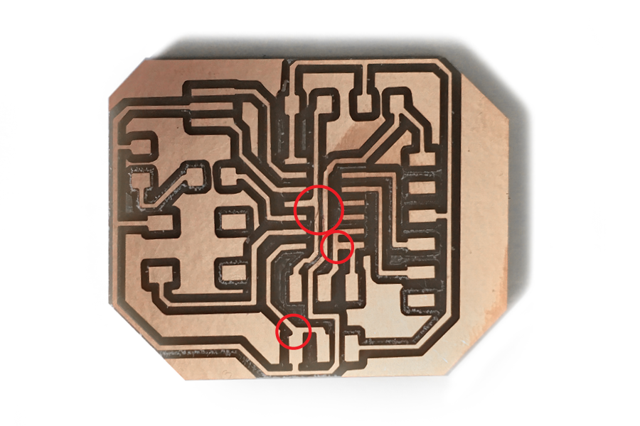
Upon closer inspection, I realized that there were more problems; together, they were all caused by inadequate distance between traces in my original SVG file. Since the file looked fine, I didn’t realize that some of the traces and footprints had merged together when converted into a milling tool path, I assume since the spaces between some of the items on my board were not large enough to accommodate the width of the 1/64 end mill.
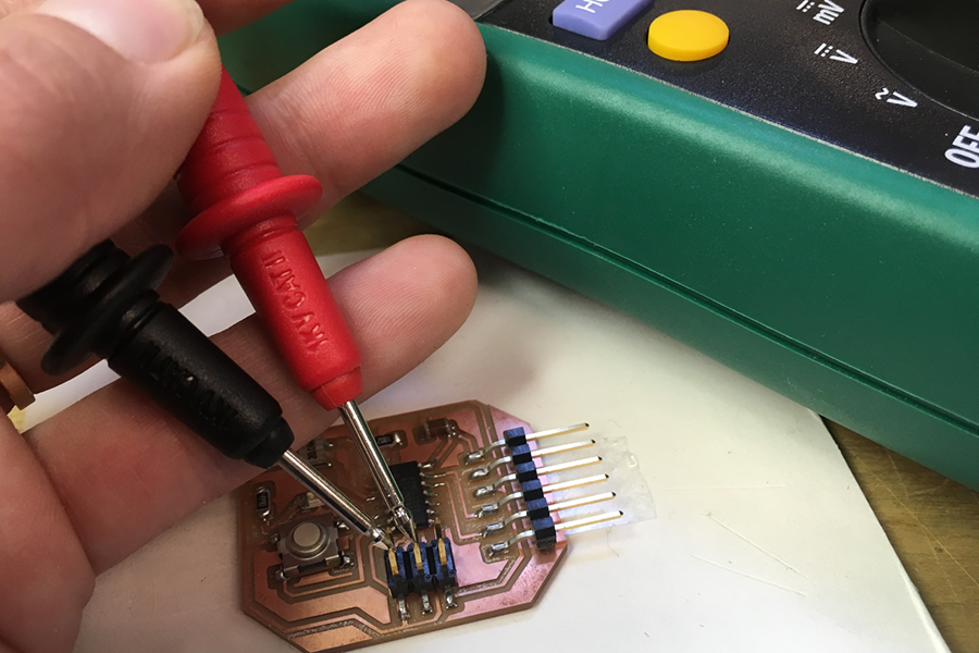
After milling, I identified one of these problems and cut out the incorrect connections with an x-acto before assembling my board. However, troubleshooting with a multimeter later revealed there was a short between two of the pins on the 2x3 header; I removed this component, fixed the traces, and reattached it, only to discover that there was an additional problem.
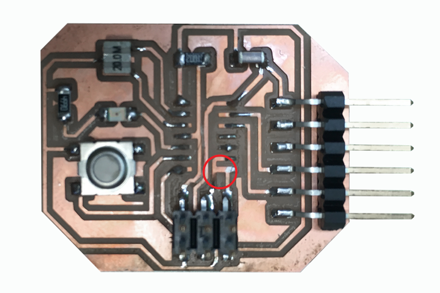
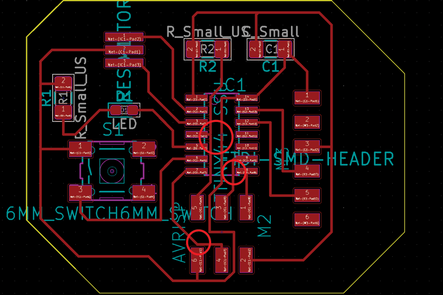
This required removing the ATTiny and performing another repair. Looking back on my earlier process in KiCAD and the SVG file I generated, the three problems are I had are fairly obvious. After everything was reattached, everything appears to be ok.
Programming
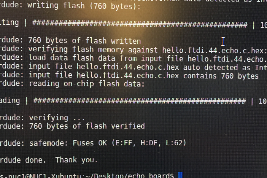
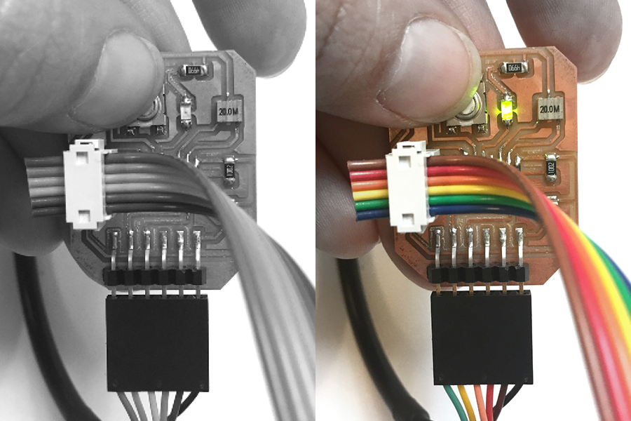
After all of the troubleshooting, I was finally able to run the Arduino "Blink" sketch on my board.
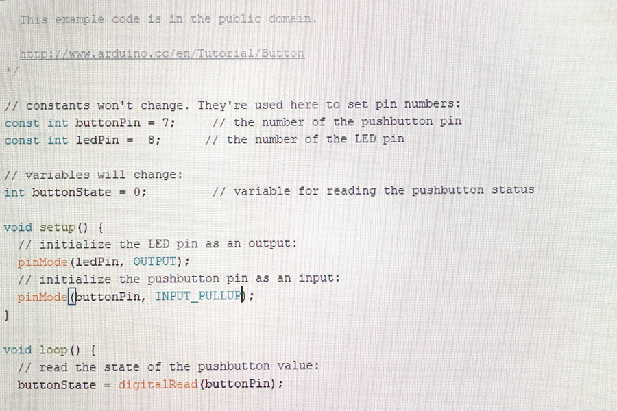
blinksketch