Molding and Casting
Design
During Make Something Big
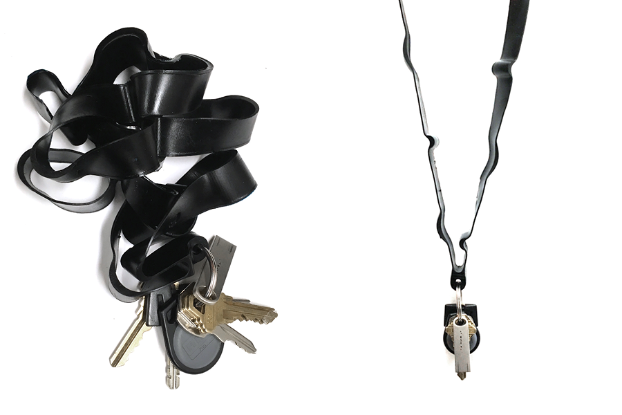
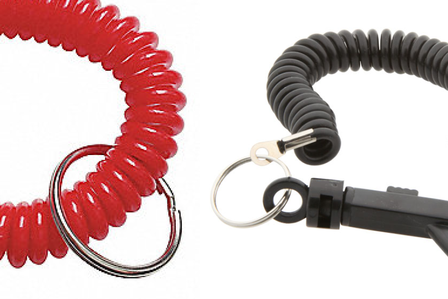
week, I used sheet material to generate objects with solid volume. In an attempt to do the inverse of this, this week I decided to use the casting process to produce a surface-like object. I wanted the cast material to have some memory
for the coiled shape, giving the lanyard some tendency to contract when not loaded with any weight (keys).
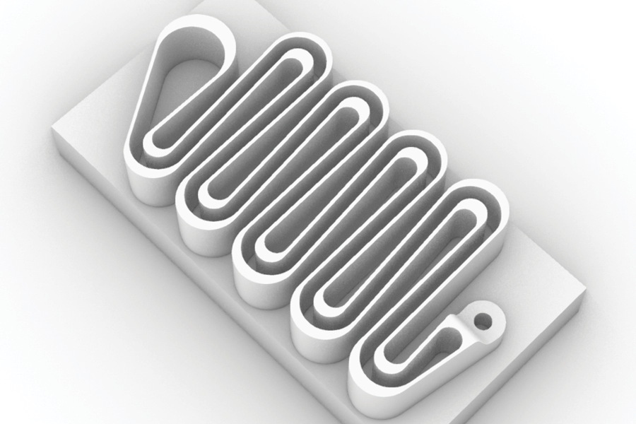
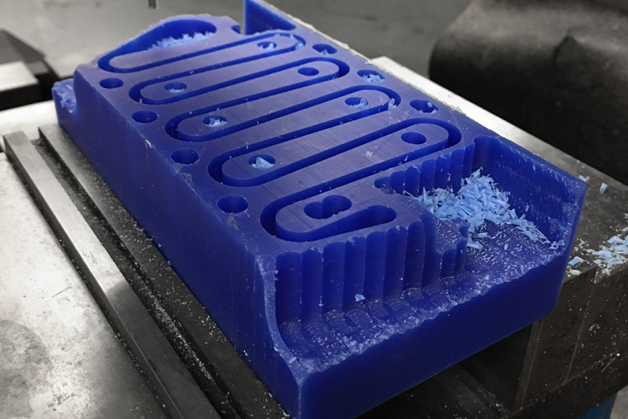
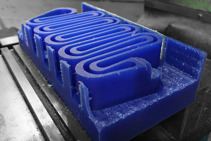
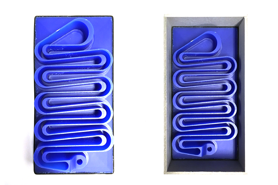
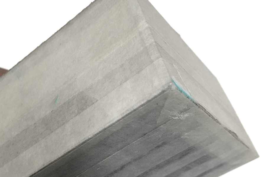
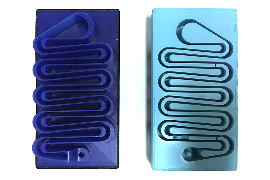
Milling the Mold Positive
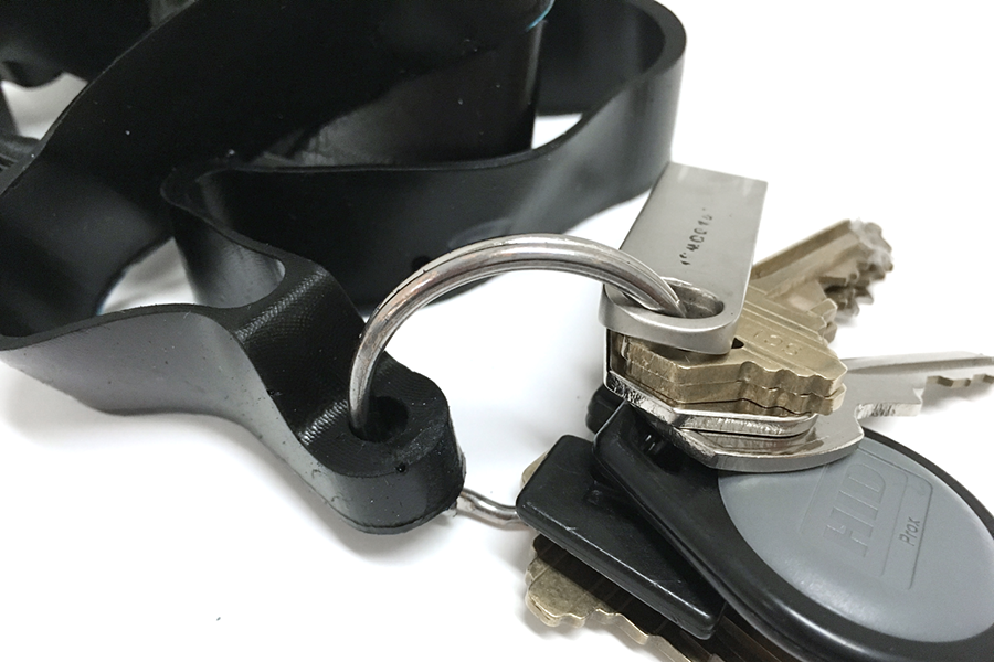
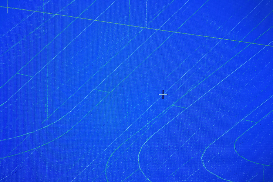
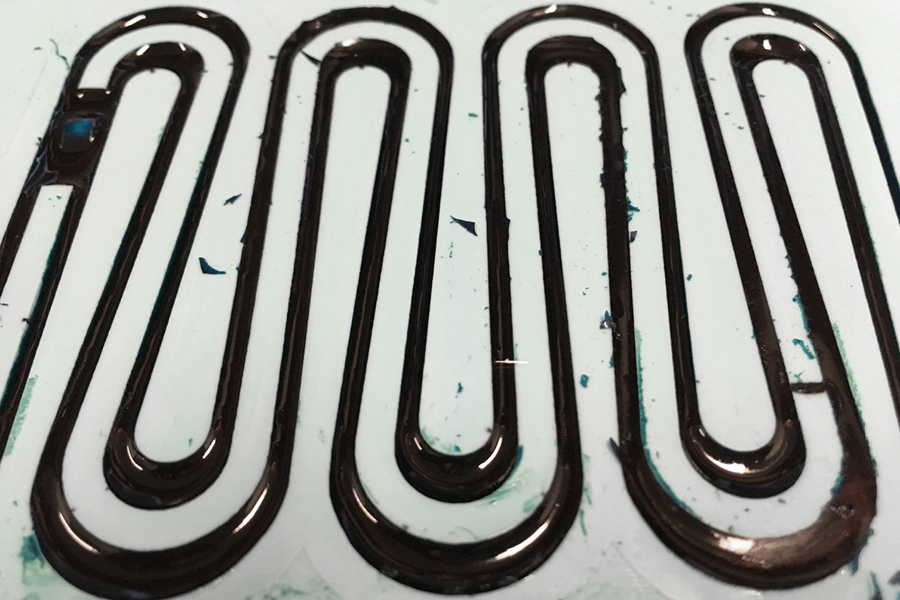
To do this, I coiled a lanyard-length line into the bounding box of the cast, leaving a minimum spacing to accommodate the width of the bits in the milling process. When de-molded, the geometry should produce a single closed loop that I can clip to my keys and wear around my neck. The entire mold has a draft angle applied, since I was worried about removing the thin material from the mold at the end.
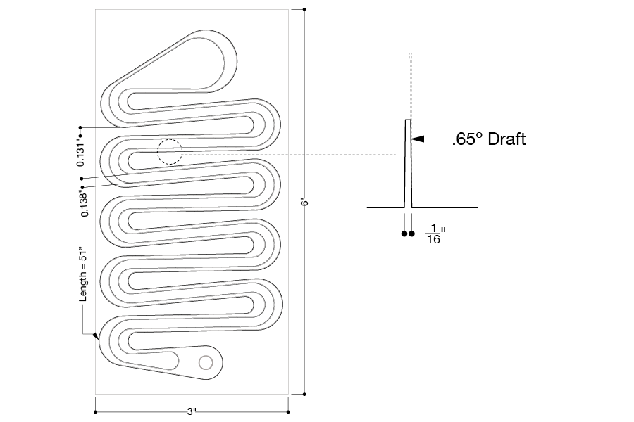
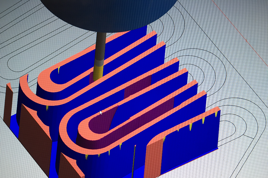
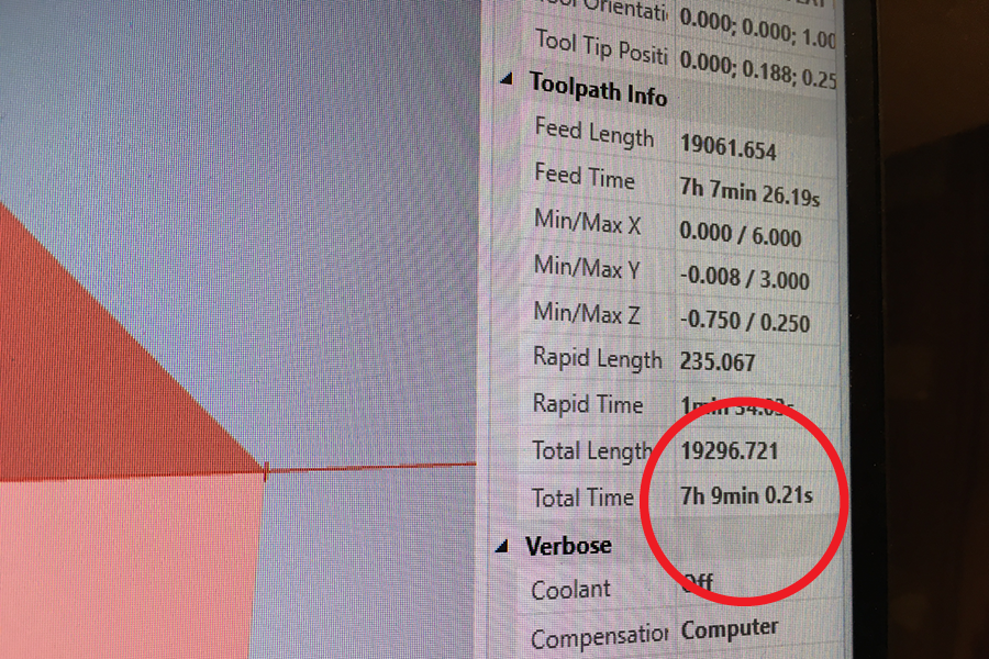
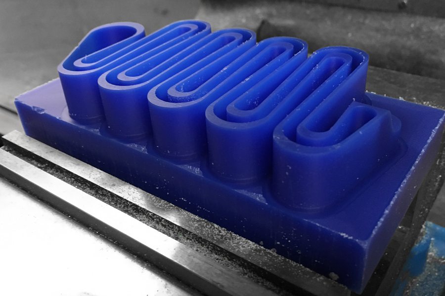
Because of the draft angle, there was some discussion about that the best tradeoff between milling time, surface finish, and geometric resolution. Initially, the final tool-path (which maintained the steep draft angle nicely) was extremely dense, resulting in an extremely long milling time.
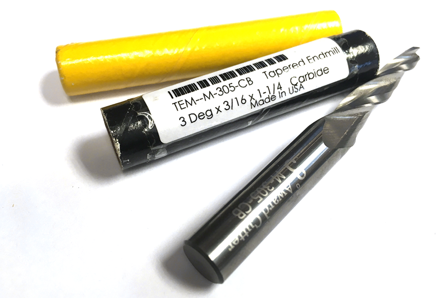
As an alternative, it would have been possible to mill the geometry with a tapered bit; however, the angle of the taper was about 2 degrees greater than what I had originally modeled. To use this method, I would have had to add more space between the surface folds in my geometry, and the tape
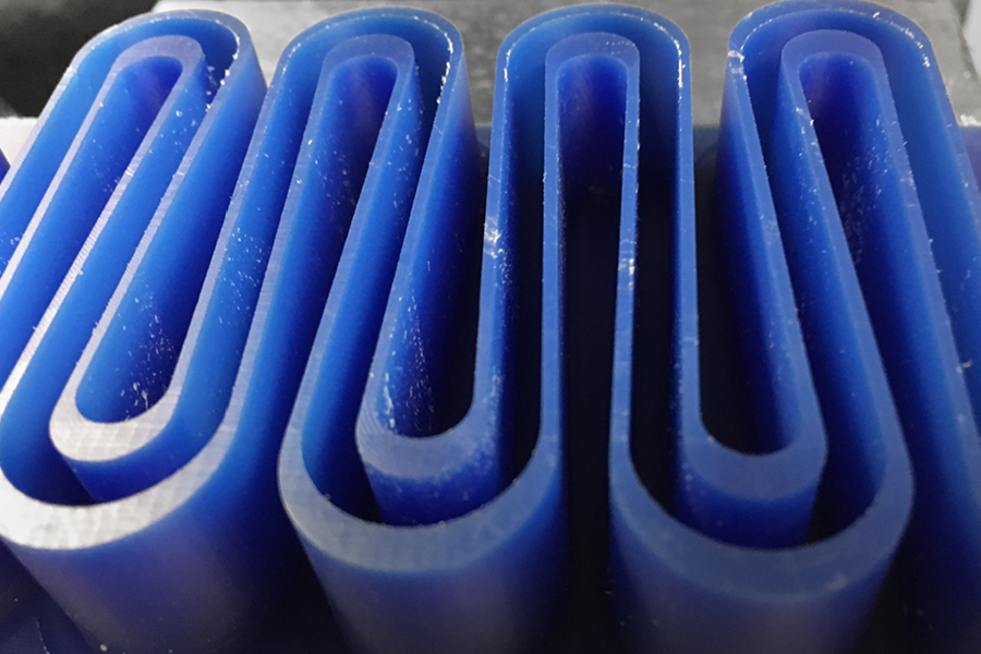
would be disproportionately thick on one side. Eventually, it made sense to settle for a courser surface finish to save time and maintain the original model geometry.
tapinessof the cast
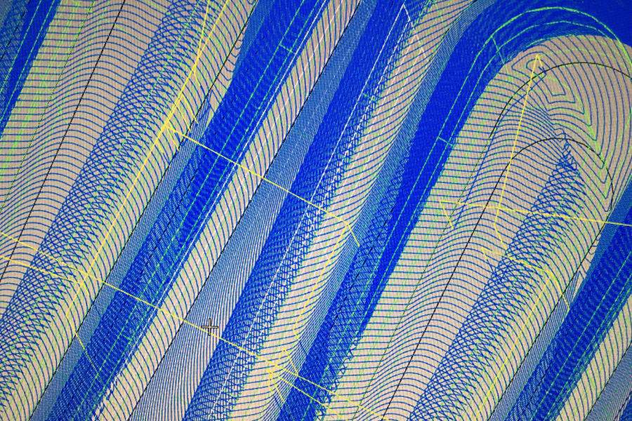
In MasterCam, the milling process used three tool paths:
- Rough cut: 1/4in flat end mill
- Contour: 1/8in flat end mill
- Scallop: 1/8in ball end mill
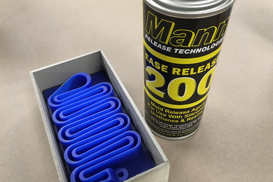
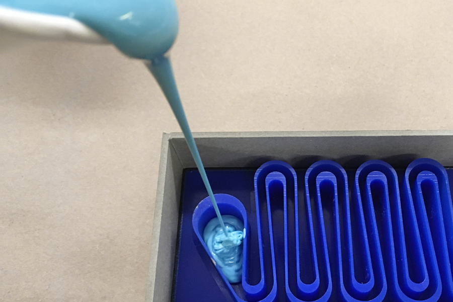
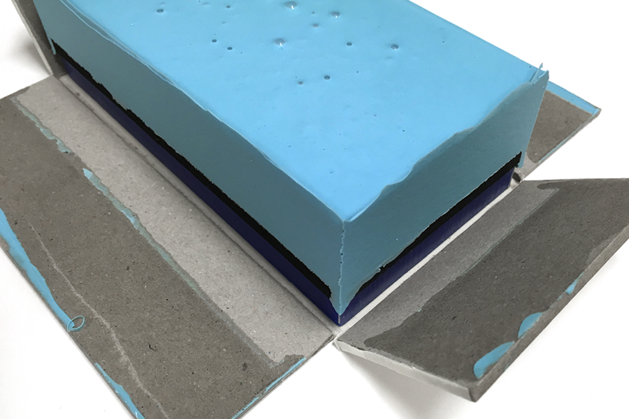
Casting the Mold Negative
Since I didn’t leave any edges around the boundary of the wax positive, I built a chipboard box around the wax, using a strip of adhesive-backed foam around the edge to seal the seam between the board and the wax to prevent leaking. I also fully taped around the bottom of the mold, just in case any oomoo wanted to leak out of the edge. I also applied mold release before pouring the oomoo.
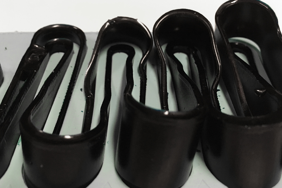
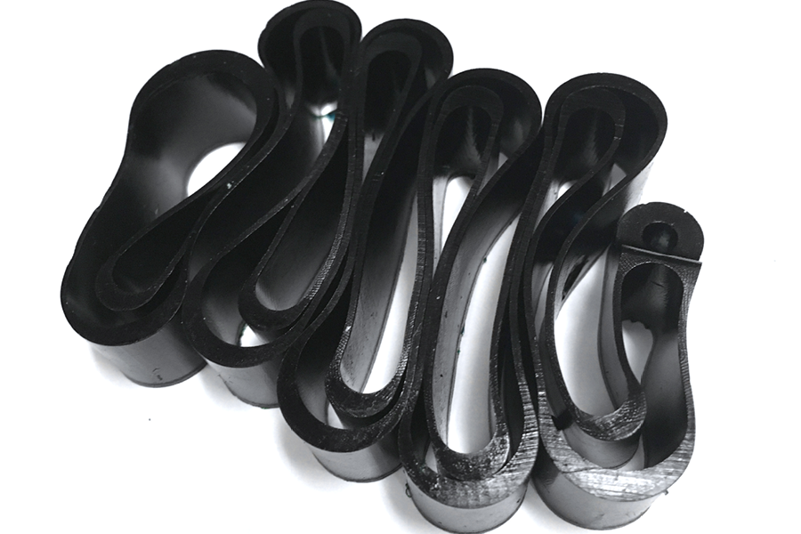
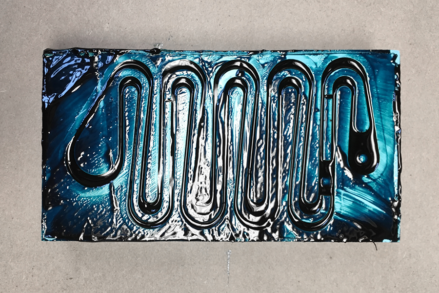
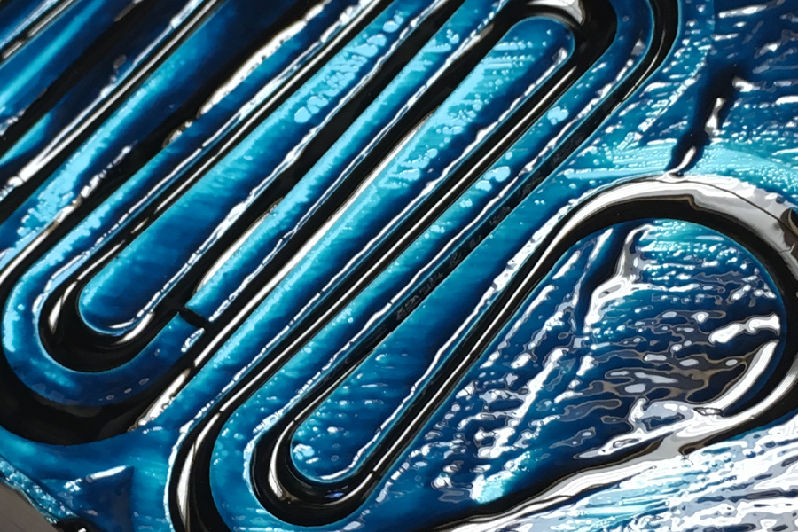
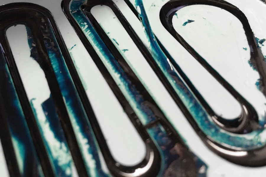
Casting the Object
I decided to use a relatively hard polyurethane rubber (Smooth-On PMC 746) for the final cast so that the result would be a flexible tape. The pigment is supposed to be green, but I added too much so it looks black.
Demolding