blinks on demand :
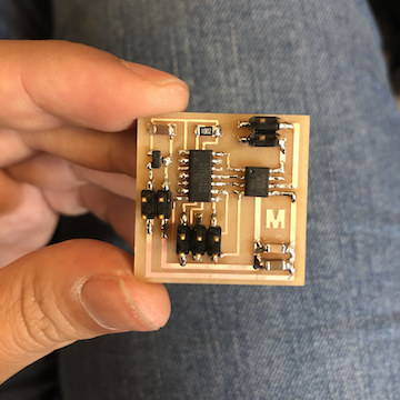
ok, well, while I should probably just play w this board, I really want to make the other board
make the motor move, thus accomplishing the assignment for the week and allowing me to continue
playing / prototyping w the motor moving forward...
I looked throughout the past year of students, and it seems none of them programmed a DC motor via
Arduino, so I was thinking this wasn't going to happen for me this week. But I kept looking online,
and searched for "controlling dc motor circuit board arduino ide hbridge". I mostly didn't understand
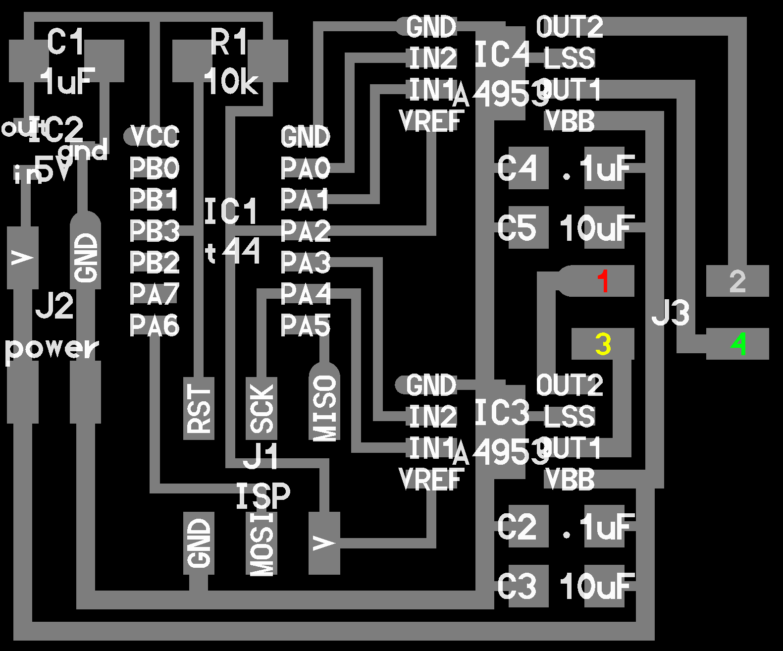
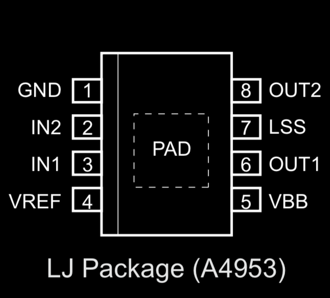
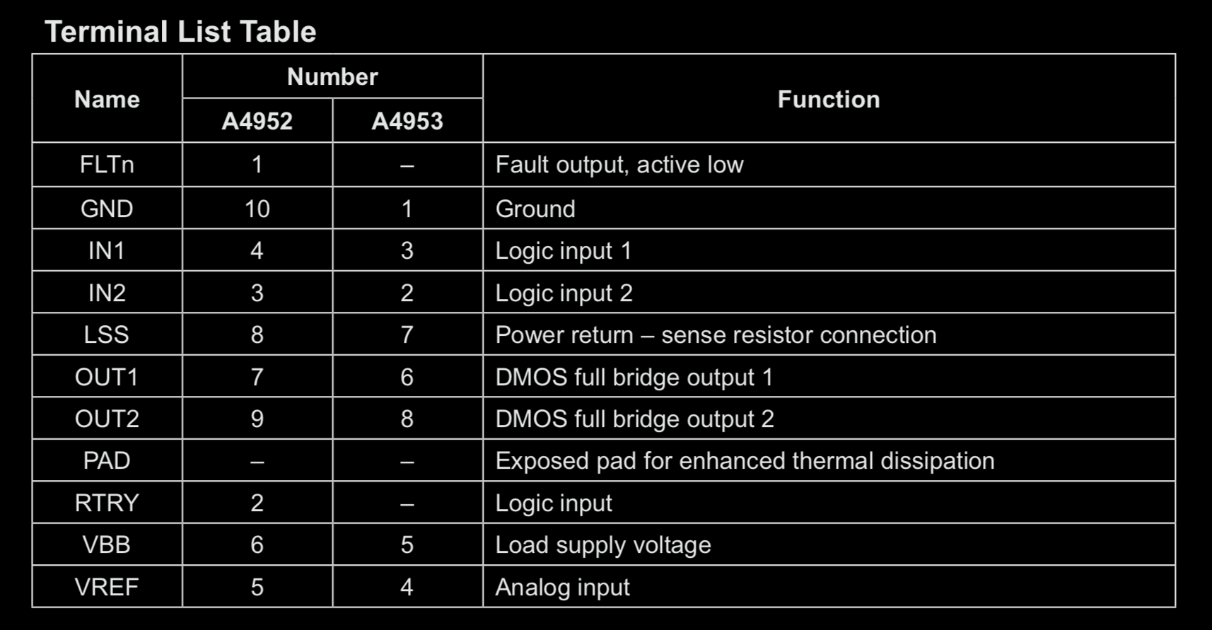
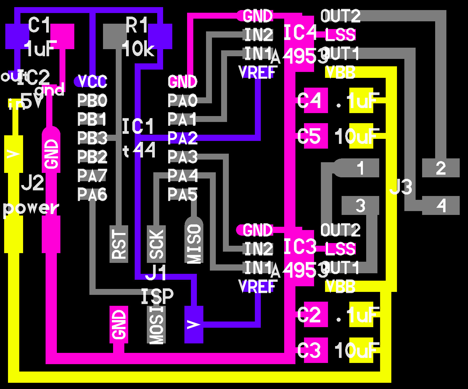
how to communicate to the motor via the hbridge. It looked like Neil's code was initializing those
pins, but I wasn't sure how to do in Arduino..
This page was what I looked at :
tutorials point.
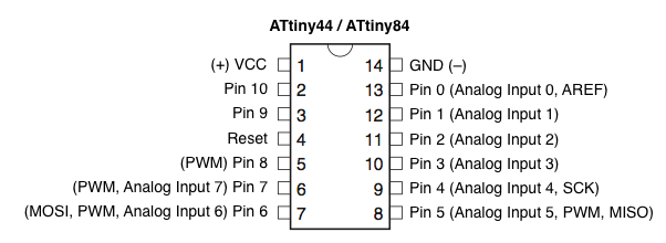
pwm pins attiny45 :
it seemed like, if i was going to go w arduino, i needed pwm and only certain pins can do that :
thankfully / luckily, pin 6 (PA7, or Arduino Pin 7) was empty and thus i chose to assign that
to PWM.
this was my code - my pins are updated according to arduino / attiny shift:
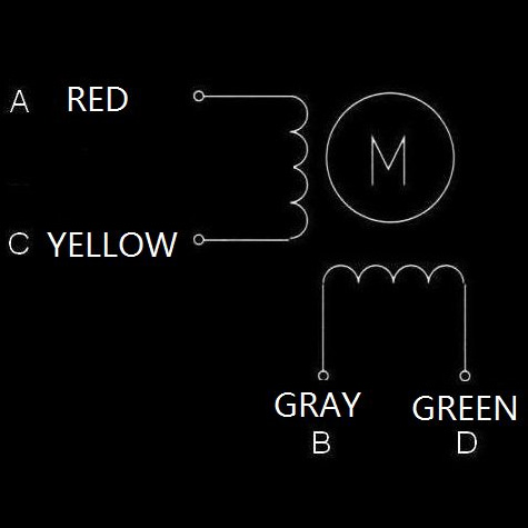
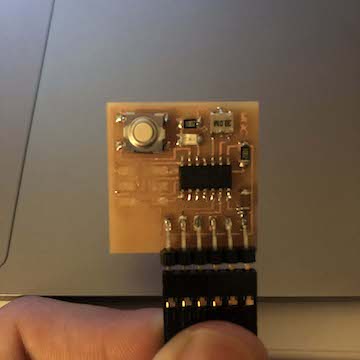
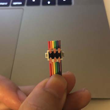
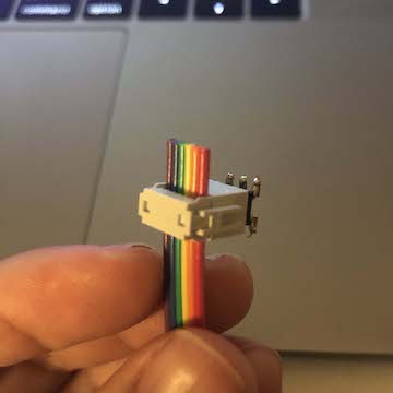
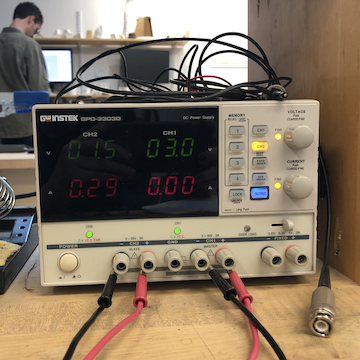
Like the echo-hello board I needed to power the motor board via the battery. As soon as the USBTiny
lit up, I knew I had the battery in the correct orientation. But I also wasn't sure about the orientation
of the motor... The motor wasn't working, and I wasn't sure if it was the board, the code, or the wiring.
So, I tried a couple of different orientations,and all of a sudden the motor starts moving!!!

!!! :
Again, I'm not sure if I'm setting this up right. I need to look into PWM more in depth. I
think something funny is going on though because rather than stop for one second, the motor
would pause for a long time before running again. I only really got it to go about three times.
i hope to visit one of the TA's for office hours, and get a better understanding on the code
i copied. but here is some more information on the code from arduino's website:
pinMode(pin, mode) : pin (the arduino pin numnber to set the mode of) /
mode (input, output, or input_pullup)
decription : configures the specified pin to behave either as an input or an output
- - - -
analogWrite(pin, value) : pin (the arduino pin to write to. Allowed data types : int.) /
value (the duty cycle : between 0 (always off) and 255 (always on) Allowed data types : int.)
decription : writes an analog value (PWM wave) to a pin. can be used to light an led at varying brightness or
drive a motor at various speeds. after a call to analogWrite(), the pin will generate a steady
rectangular wave of the specified duty cycle until the nect call to analogWrite() (or a call to
digitalRead() or digitalWrite()) on the same pin.
- - - -
ahh this is helpful
pulse width modulation, or pwm, is a technique for getting analog results with digital means.
digital control is used to create a square wave, a signal switched between on and off. This
on-off pattern can simulate voltages in between full on (5 volts) and off (0 volts) by changing
the portion of the time the signal sends on versus the time that the signal spends off. The duration
of "on time" is called pulse width. To get varying analog values, you change or modulate,
that pulse width. if you repeat this on-off pattern fast enough with and LED for example, the
result is as if the signal is a steady voltage between 0 and 5v controlling the brightness of the LED.
- - - -
digitalWrite(pin, value)pin (the arduino pin number) / value (HIGH or LOW)
description : write a HIGH or LOW value to a digital pin. if the pin has been configured as
an output with pinMode(), its voltage will be set to the corresponding value : 5V (or 3.3V on
3.3V boards) for HIGH, 0V (ground) for LOW. If the pin is configured as an INPUT, digitalWrite()
will enable (HIGH) or disable (LOW) the internal pullup on the input pin. It is recommended to
set the pinMode() to INPUT_PULLUP to enable the internal pull-up resistor. If you do not set
the pinMode() to OUTPUT, and connect an LED to a pin when calling digitalWrite(HIGH), the LED
may appear dim. Without explicitly setting pinMode(), digitalWrite() will have enabled the internal
pull-up resistor, which acts like a large current-limiting resistor.
- - - -
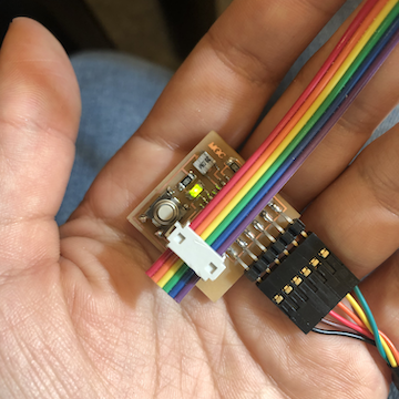
Regardless, I'm pretty happy with the results. Hopefully I will see someone for office hours
sometime this week and start adding things (like a button / switch?) to play w this motor
and finally begin to prototype my moving mechanism!

correct delay() :
I put an issue in the issue tracker asking about why my motor would be so off (instead of 3 seconds,
it was going for 2 minutes / instead of 1 second, it was going for 1 minute), and Anthony responded
that I probably had the internal clock set incorrectly. I was previously programming my blink board
with indeed had an external clock of 20 Mhz, and this indeed was the problem.
During office hours, Anthony pointed out other problem with the code. For whatever reason, I
thought the PMW had to be assigned to an "empty" pin, but actually, you have to assign it to
a pin that is indeed doing something. He said it probably wasn't an issue, though since I was
setting the pins to LOW / HIGH...
Although the delay() was now working by adjusting the clock setting, the code was meant to turn
the motor one way and then the other, and at the moment it turns one way, skips the other way,
and then turns the same way. So there is still some debugging to do.
One other note : After trying the motor a couple of times, the initial code I was using
actually stopped working. The motor would work when we put a battery to it, but not via the board.
Anthony lent me another dc notor, and I believe this one had a resistor whereas the other did not?..
Anyways, this motor is working whenever I connect it to my board.
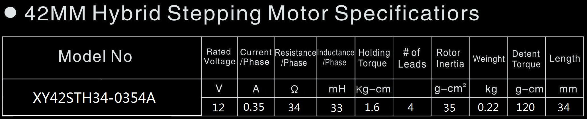
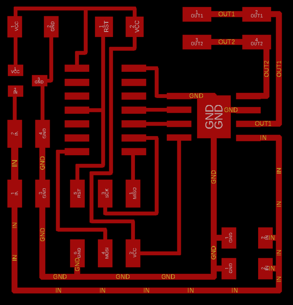
Anthony told me this board could power motors up to 40 V, but that the driver would heat up a lot,
so I should provide more surface area ground to dispell heat vs v thin traces. I dont need
a super super fast motor, but I do think I'll need something more powerful than this current motor.
Here is the code Anthony adjusted w me (removed pwm and both breaks which were written incorrectly):
woohoo :
Turns out, I was assigning the wrong pins, that is why only one direction worked.
Here is the corrected code. I'm not sure if my PWM is doing anything if its not connected
to the motor driver.....
Here is code to make the motor
e forever - though you could just do this by connecting
to a 9V battery.