initial idea :
09 / 19 / 19 : what type of conveyor belt will i make?
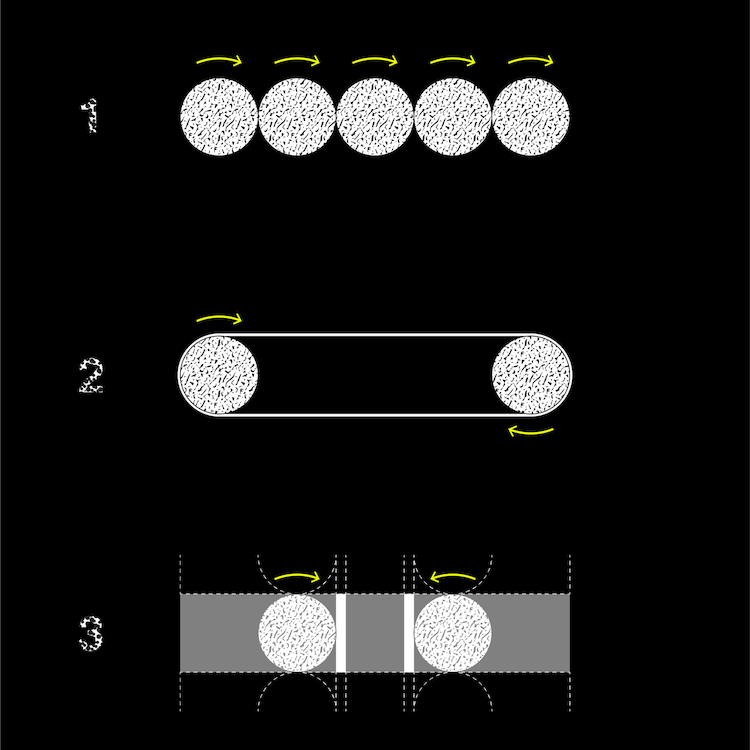
conveyor types :
Before beginning to design anything, I realized there was a need to clarify what kind of
conveyor I would be making, as there are various types.
I was able to identify three types I was potentially interested in making :
1 ) the roller conveyor : rolling dowels in continuous rotation allow objects to move
across their surface
2 ) conveyor belt : two rollers in continuous rotation allow a belt to move across them
3 ) plate conveyor : plates are pushed via short vertical dowels in oppositional rotation
*diagram 3 is in plan*
julio's conveyor belt : (source : hbo)
As previously stated, Julio Torres' HBO Special,
"My Favorite Shapes" was my initial inspiration.As such, I decided to look at
what kind of conveyor his was. His conveyor curves from the back of the stage to the front,
but it doesn't seem to be one continuous piece, which I am interested in.
close up of julio's conveyor belt: (source : hbo)
What I really like about Julio's conveyor is that even though it has curves, the conveyor reads
as continuous throughout. From my initial research, I found that often, when conveyor belts
curve, they introduce a different kind of conveyor type, making the conveyor's form read as
broken up into various modular pieces
Julio's conveyor belt initially confused me because even though it looks like a Type 2,
classic conveyor belts cannot, in their conventional form, take curves. Yet the entirety of
Julio's conveyor belt reads as homogenous. It can't be a Type 2!
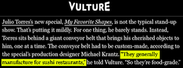
vulture article :
here
After doing some research, I discovered the belt was manufactured by a company that often
works for sushi restaurants, which I would say falls into
Type 3.
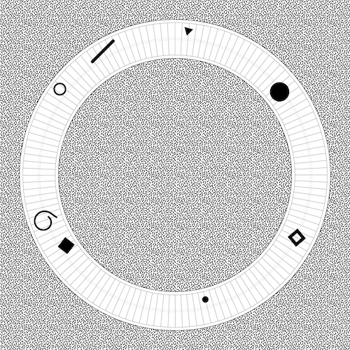
sushi belt's circular / crescent plates : (source : wall street journal)
I didn't initially think Julio's conveyor belt was a plate conveyor belt, and I especially
did not link it to sushi conveyor belts because those typically have a recognizable circular
plate that allows for plates to take a curve, kind of like a baggage carousel.
Knowing I wanted to make circular, continuous form, I decided to pursue Type 3, though
I would try to design a plate that, as in Julio's conveyor belt, did not reveal it's mechanism.
09 / 26 / 19 : what shape will my conveyor belt be?
conveyor shape :
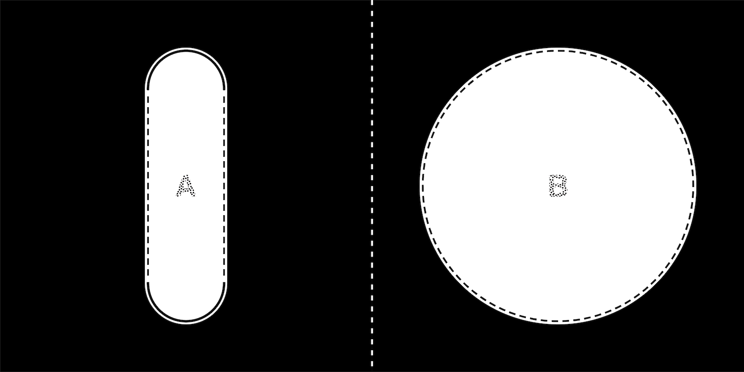
Initially, I was interested in both a kind of pill shape and a circular shape. In general,
I wanted a looping conveyor belt.
Researching the different types as well as just thinking about what the different profiles
provided helped narrow my choice.
shape a : pill
SHAPE A : meant non/continuous curvature. That is, you have two straight segments,
and half donut shapes at the ends that connect the two. This reminds me of the very typical
sushi conveyor belt.
shape b : circle
SHAPE B : being a circle, meant continuous curvature. In this sense, I wouldn't have
to conceive of the plate as taking a curve, rather the plate is curved, though this is curve
would be quite subtle. Shape B also begins to become spatial.
circular conveyor belt forms a small "room"
With the correct proportions / dimensions, I could imagine someone being inside this circle,
presenting the objects on it (like Julio does in his show), while people walk around it.
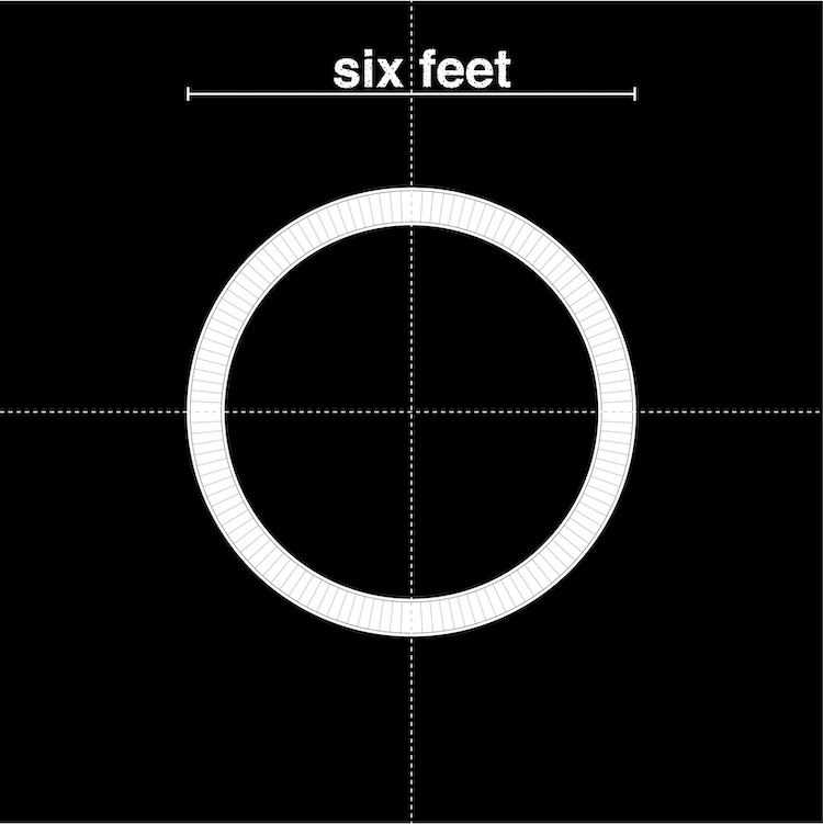
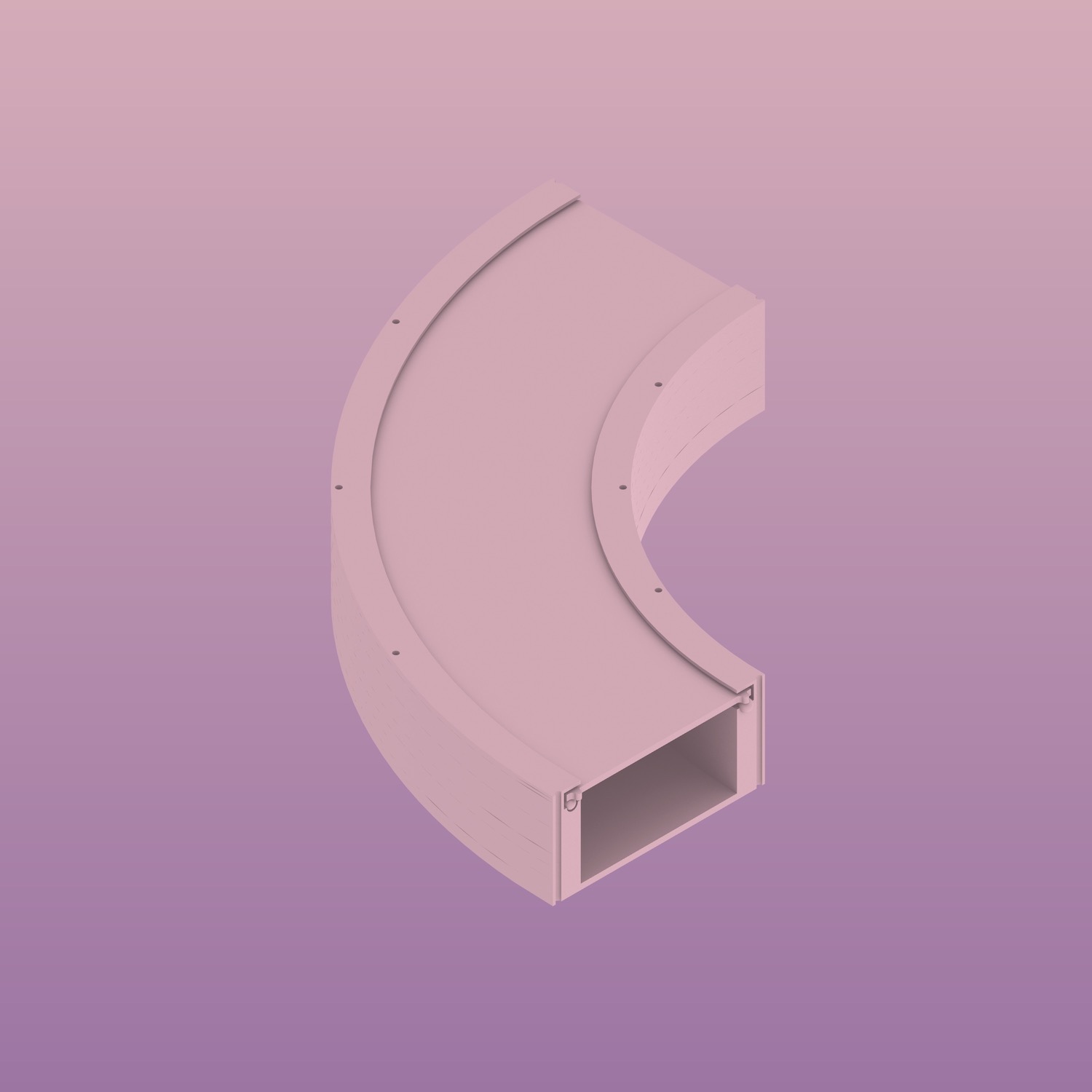
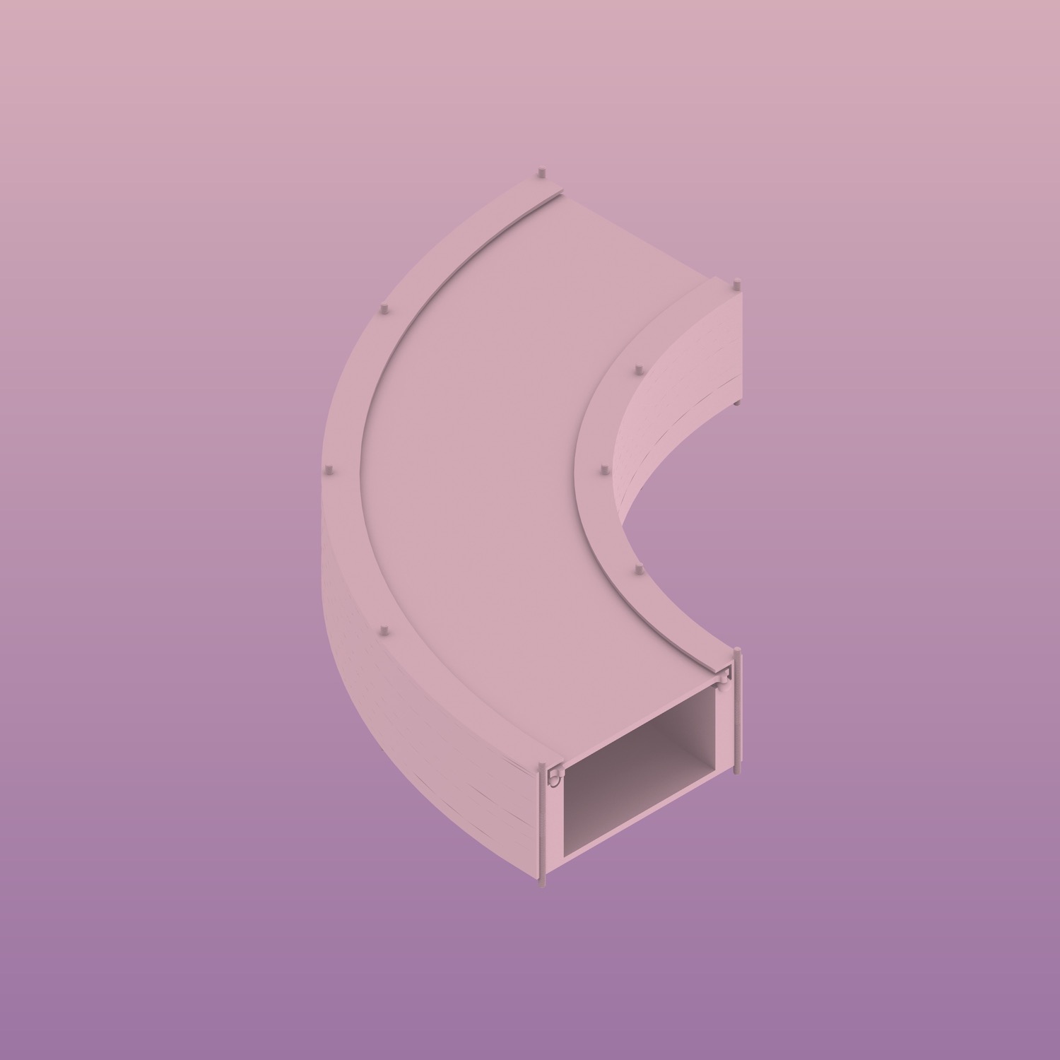
belt made of 4 modular parts
Although I want one continuous conveyor belt, due to it's size (hopefully an outer diameter of
around 6 feet) it's possible it will have to be fabricated as smaller parts that, then, in
their assembly are camouflaged into looking as though it is one continuous circle.
Thus, I am thinking about dividing the circle into 4 quadrants.
09 / 27 / 19 : how will my conveyor belt move?
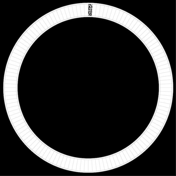
one plate :
Now that I've vaguely defined the overall dimension / proportion / shape of my conveyor belt,
I think it is time to diagram how one plate would move along the circle.
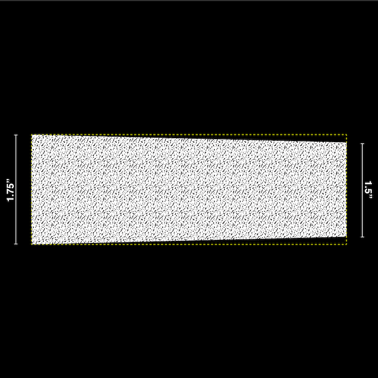
single curved plate : plan
As mentioned previously, due to the circular shape, the plates will have a slight though
continuous bend.
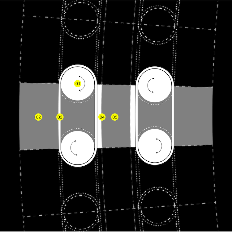
diagrammatic kit of parts :
In order for the plates to move, the belt needs to incorporate the following :
1 ) rotational gear : unsure of how many need to be motorized vs connected to
motorized gear *note that gears across one another rotate in opposite directions in order
to push plate in and away
2 ) plate : above, hiding mechanism below
3 ) gripping band : connects gears / where surface of moving band begins to move base plate
4 ) base plate : connects plates to one another and allows plate to sit in conveyor belt base
5 ) rail / channel : in which base plate sits
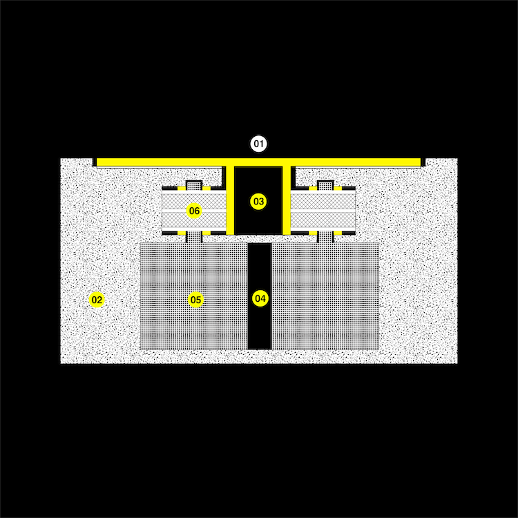
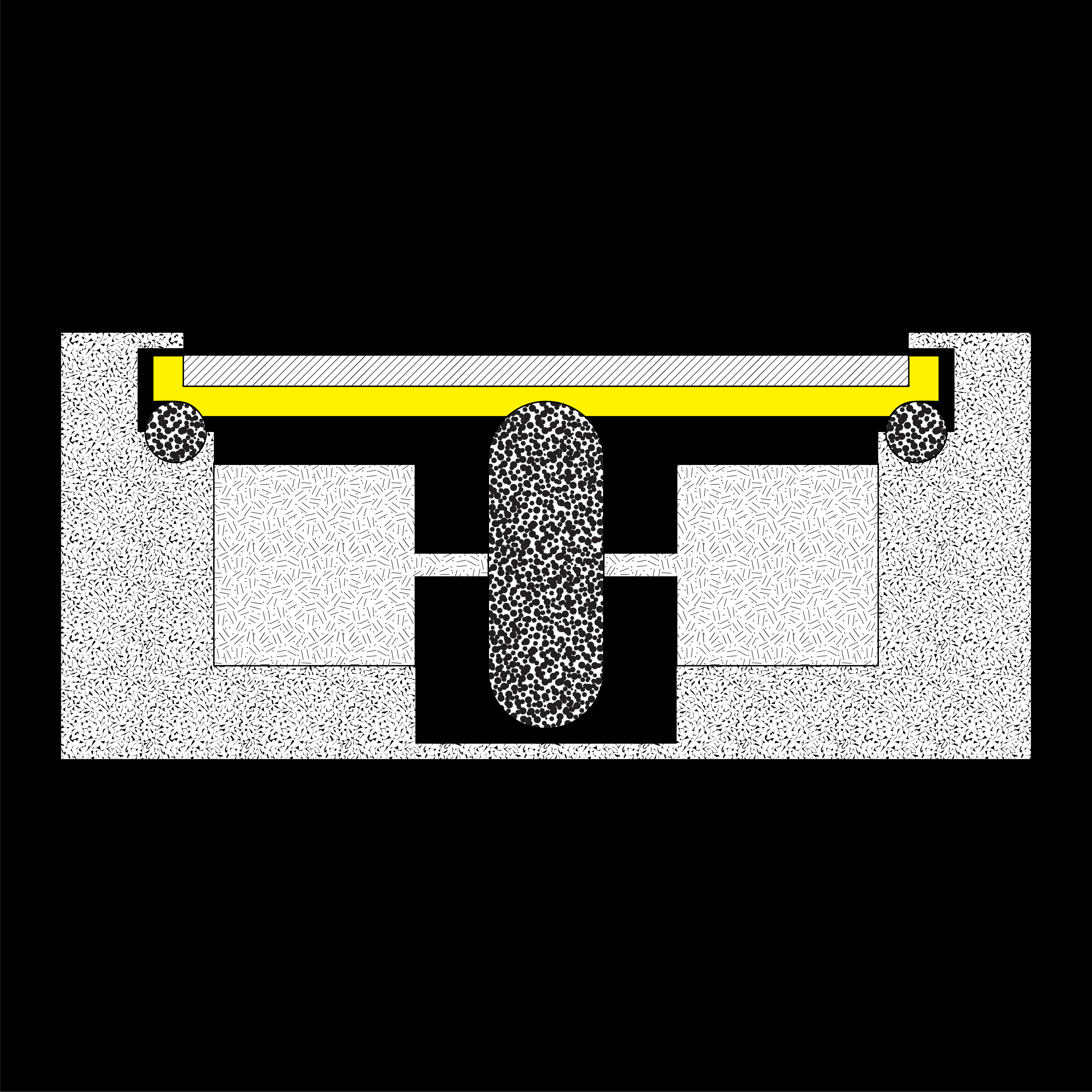
diagrammatic section :
1 ) plate : 5" long / 2 ) base : outer diameter of 6' / 3 ) rail /
channel : holds plate / allows movement via gears / 4 ) lower cavity : to
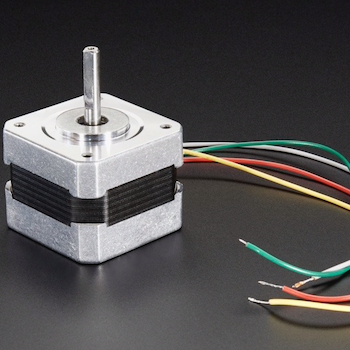
store motor / wires / etc / 5 ) motor : currently modelled as "Stepper Motor NEMA-17"
/ 6 ) gear with bands : upper bands connect pair / lower bands connect neighboring pair
I can't say whether any of this is actually true. Sounds like it might be time to prototype
some gears?
10 / 04 / 19 : a simpler mechanism
simplified section and other ideas : ty paloma !
I asked to meet with Paloma to talk about my final project. I had gotten a quick "yes, go ahead"
from Jen and Neil, but I had yet to discuss specifics with anyone.
Paloma's advice was to simplify the moving mechanism. Yes, the conveyor belt is quite large
(which she suggested considering making smaller, but I do feel strongly about making it 6' wide)
but it can be thought of kind of like.. a toy train that just moves in one circle - in that
sense it's not really even turning.
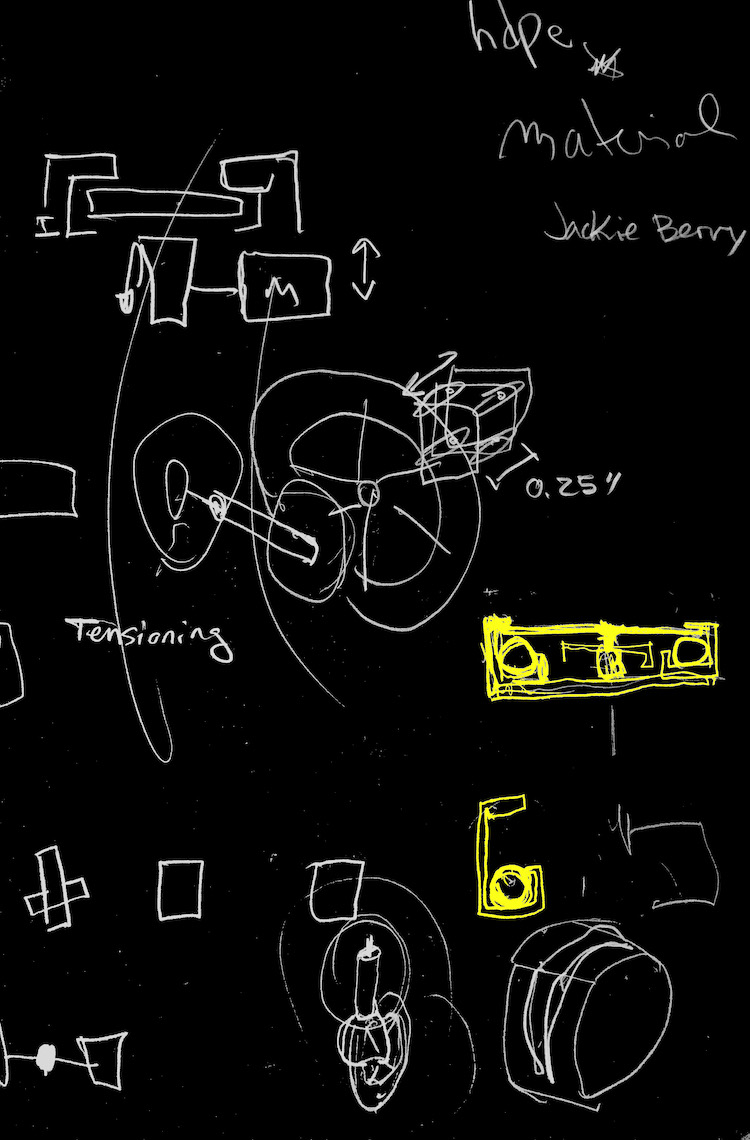
new conceptual section with lip + ball + wheel :
Paloma also mentioned that I would want to incorporate:
1. lip detail : that kept plates from popping out of the belt
2. ball detail : in order to reduce friction, and thus, heat
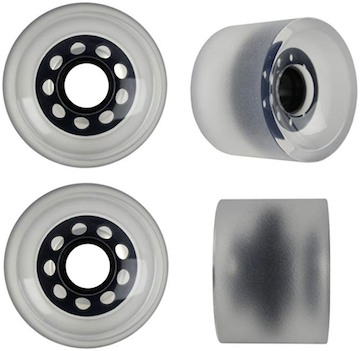
3. wheel mechanism : that would pull the plates along the circle - though her friend who was
at office hours (whose name I missed), suggested this wheel be stationary. Paloma mentioned
this wheel could be a rollerblade wheel or I could make my own.
Along these lines, Paloma suggested taking a look at
Jackie Berry's final project, which included rubber cast wheels, which was super helpful.
Jackie's mini robot also included a
adafruit
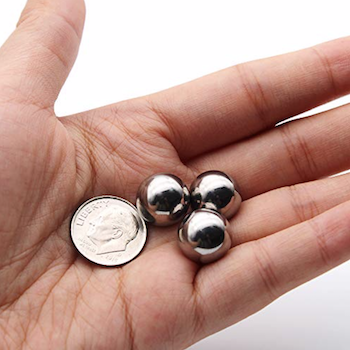
3/4" metal ball caster, which then pointed me to looking at metal balls for the other
detail.
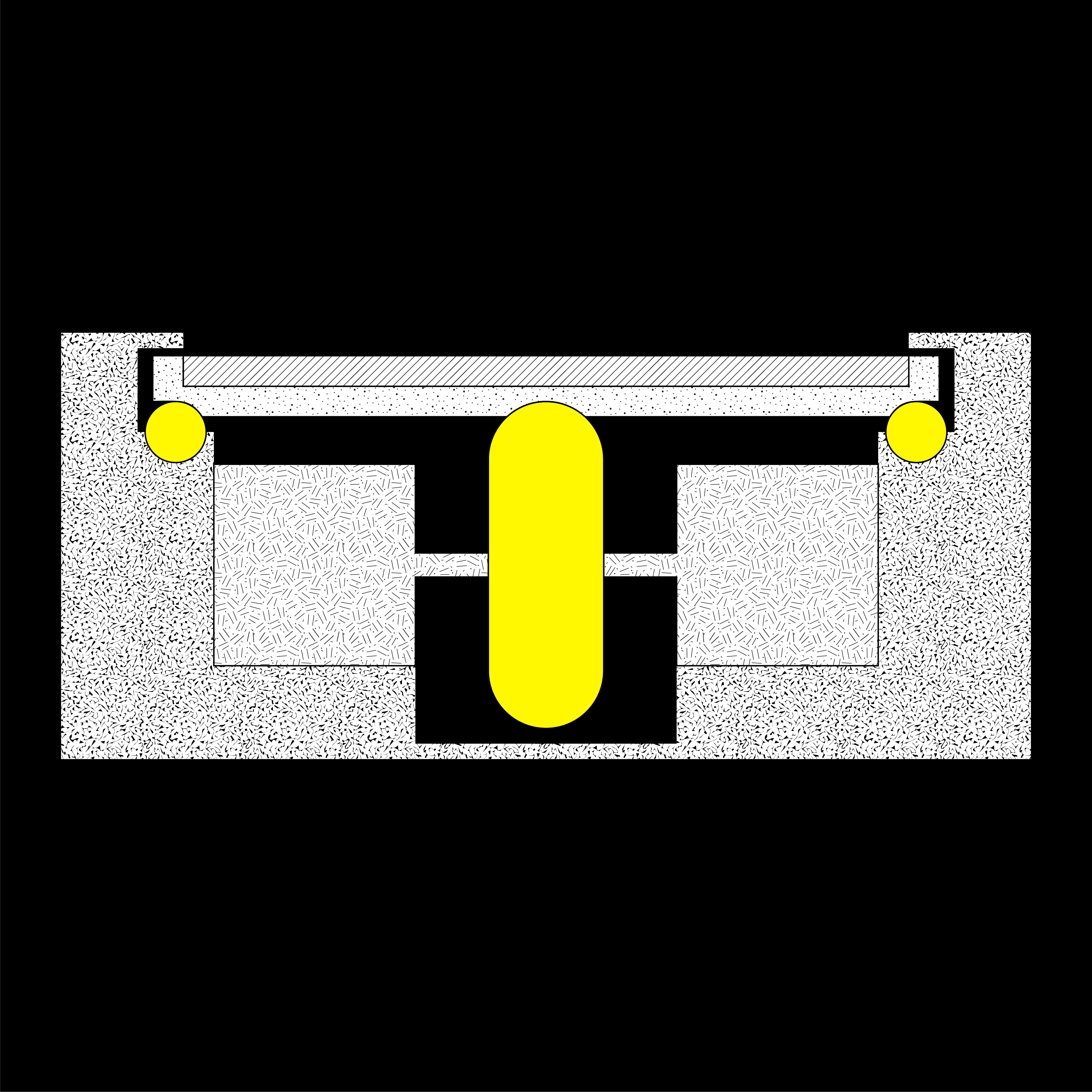
10 / 15 / 19 : preparing for first prototype
new section drawn :
According to Paloma's feedback, I redrew what could be the section for the conveyor belt.
A lip holds the plate in, small 1/2" stainless steel balls allow for the plate
to move with little fiction, a stationary wheel is motorized / held by two stepper
motors.
The last detail, I'm most unsure about, but I figured two stepper motors supporting one wheel
could either 1) be twice as strong, or I could switch motors for different directions, always
using one motor as a kind of ball bearing. That is, I am using two motors to motorize the
wheel but also to support movement of it - not sure if that makes sense.
*Paloma did not suggest a stepper motor, as stepper motors deal with a kind of precision I
don't really need for this project. BUT, alas, I had purchased a couple after seeing the
3D printed motorized sphere in class. I was impressed with the little amount of sound it made -
sounds it also someting I am worried about - and how fast it moved (thought I wont need ULTRA
speed and I wont be carrying huge items). Admittedly, it was a naive purchase, but I don't
think it would be totally inappropriate to use it?...*
plate holder detail :
A detail I added was a kind of plate holder. I'm not sure what material this would be,
but it seems like the plate wants to have a good grip on the wheel that is pushing it, as
well as the marbles that facilitate movement but also function to hold it in place.
The reason I think this piece would be separate from the plate is because I think the plate
would be cut via the water jet. I wouldn't want to mill aluminum as that process is complex,
especially when there are so many of them.
I imagine this piece could be 3d printed, but considering the fact that there are ~130 plates
it could also be milled HDPE - which is good for reducing friction?
Along these lines, I'm a bit unclear how I will be making this out of a metal material. It's
possible the outermost part of it will be steel and its interior components might be MDF or
HDPE for a couple of reasons : stock size / cost, and friction. For example, the chanel that
holds the marbles - shouldn't this be HDPE?
It's clear I need a lot of questions answered to move forward, so I went ahead and purchased
some materials to prototype in the coming week(s) :
stainless steel marbles to reduce friction : purchased via amazon
rollerblade wheel to produce movement : purchased via amazon
stepper motor to move wheel and plates : purchased via adafruit
The hope is I will start to prototype a small section of the conveyor belt this week -
maybe in aluminum, but maybe in acrylic - the plates for sure will be water jet aluminum.
The coming assignment is to make our board do something, and I am hoping I can get these motors
moving!!!
10 / 20 / 19 : no nO No NO stepper motor!
Today I met with Anthony to speak about my board that wouldn't blink, but once we figured
that out, we discussed my final project briefly.
some things came up :
1.) I should not use a stepper motor! Anthony said this would complicate my project unecessarily.
2.) Like Paloma, he suggested a DC motor would be appropriate for my project. We both
agreed, I would need a somewhat powerful motor in order to move my conveyor belt, which, while
thin is big and made of aluminum(fingers crossed).Anthony suggested I ask for a DC motor from
RPL and test it beginning with a dc power supply.
3.) it's likely the motor set up would be : motor shaft going through wheel and then into a
bearing - load is reduced via the steal bearings, but there is still likely to be some torque
on the motor, thus the need for a bearing connected to the end of the shaft turning the wheel.
4.) rather than assume perfect tolerances, the motor / wheel assembly should be adjustable :
that is it can move up or down in order to get the moving wheel making contact with the plates so
that they moving as they should - a heavier plate might also help...
5.) The plates should be linked or be incredibly thick, in order for the plates to not be pushed
on top of one another. This linking mechanism does not have to be aluminum, but it also doesn't
have to respond directly to the wheel and steel bearing below it, as previously drawn.
6.) The wheel that will move the plated should be flat, if possible, not rounded as currently drawn.
longboard wheels : purchased via amazon
wheel bearings (also for skateboards): purchased via amazon
I figured this might be the case, and had already ordered skateboard wheels earlier this week.
7.) finally, anthony strongly suggested that I should make a scaled version for the
class, and only attempt the 6' conveyor belt once I have a handle on that. Like Paloma,
Anthony asked me why I wanted to make something so big. It has to do with my research, my
interest in objects that begin to function at the scale of architecture... But, I think he
is right - I have been feeling overwhelmed with the thought of making something so big, when
I'm already trying to answer questions I've never considered before. He said it would be
easy to scale up once I had a scaled down version working. This sounds like a good idea to
me. I also think I could start to test different part of the belt separately, rather than
test all of the components in one go.
Moving forward, I really want to get a motor moving, and then apply that motor to a moving wheel
to a series of plates.
10 / 21 / 19 : playing w a dc motor
***a lot of this section is discussed in
WEEK 07***
Yesterday, Anthony mentioned I should try to play w a dc motor, see what its like, possibly
prototype a scaled version of my conveyor belt with it. That sounded easy enough, what I was
intimidated by was making a circuit board that could control a dc motor. So, I attempted both.
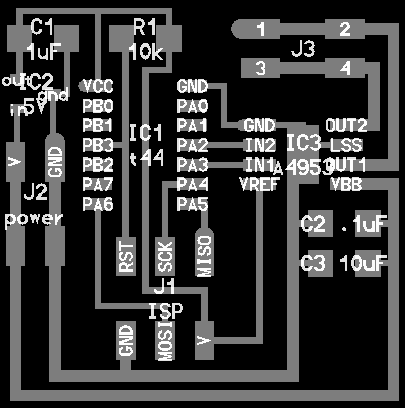
Neil had a dc motor board, which I redrew in Eagle :
neil's board :
my redrawn board :
When I was redrawing in Eagle, I added a button and an LED so I could see if the board was
working but also to try to control the motor w the button, but I was worried I would mess it up
and decided to keep it simply and stick strictly to neil's board. I kind of wish I had added, though...
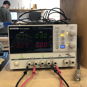
dc power supply to test dc motor:
Before attempting to connect the motor to the board, I powered it using the dc power supply.
This was easy and exciting. The motor runs really fast at 5, but can run quite slowly around 1.5v.
from 0 - 4.9v :
So now - to program the motor board... tbh i don't quite understand neil's workflow, and feel
a lot more comfortable with arduino as an ide... however, i can't just copy neil's code if
i'm to go that route..
i mostly was unsure about how to write code in arduino to talk to motor through the motor drive / h bridge.
I looked at a lot of students' pages from last year but people usually used a servo or a stepper and
if they did happen to use a dc motor, they used neil's code.
I ended up googling "controlling dc motor circuit board arduino ide hbridge" and found what i
thought was a helpful
tutorial.
In the tutorial, they are also using a hbridge, though a different one, and they bring up
PWM,
or
pulse width modulation. The tutorial explained that an hbridge is used to drive a motor
in two directions, and the
data sheet for the a4593, the motor driver neil uses in his board, also mentions this.
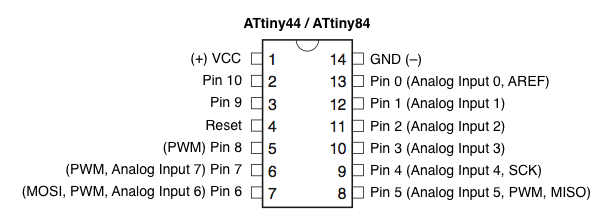
attiny44 pin out : pwm pins
Turns out, only a couple of pins on the ATTiny 44 can be assigned as pwm. Thankfully / luckily,
pin 6 (PA7, or Arduino Pin 7) was empty and thus i chose to assign that to PWM.
Here's the arduino code i used, which is copied from the tutorial, though I've switched to
correctly pin to ATTiny44 :
My hopes for this working were quite low (i feel like something always goes wrong, but after
figuring out the orientation of the battery and the motor, the motor started to move!
a moving motor via a programmed circuit board :
something is up, though because the motor would move for wayyy more than 3 seconds and would
stop for way more than 1 second, and I only got it to work around 3 times...
but even so.. i kind of feel like my conveyor belt is not so crazy just by seeing this motor
move. i'm encouraged i'll be able to baby steps it all the way to the end.
i hope to visit one of the TA's for office hours, and get a better understanding on the code
i copied. More information on the code (
pinMode(), digitalWrite(), analogWrite(), and
pwm can
be found in
WEEK 07.
Even though this motor is quite small, I think I should use it to prototype a scaled
version of my conveyor belt.
10 / 22 / 19 : dc motor arduino code corrected
Today I went to office hours, and Anthony revealed I had selected the incorrect clock and thus
my delay was off by a factor of 20!
I though I would have to make a vastly different board in order to power more powerful motors,
but Anthony also told me that I could power motors up to 40v, though I would need to consider
more surface area for ground so the motor driver burn up!
I think moving forward, I'll play around w Neil's board, and add things that allow me to
control the motor and prototype the mechanics of the conveyor belt! Super excited to move forward -
this somehow feels like a huge breakthrough, though its a small accomplishment to make a dc
motor move w a board i didn't even design...
10 / 23 / 19 : motor print test
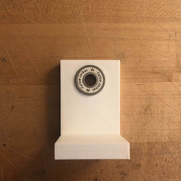
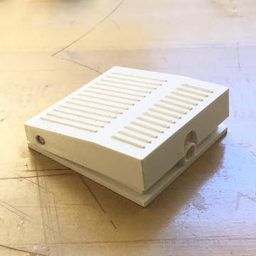
supports / motor attachment test :
enthusiastic about my motor movement, I decided to make some tests based on parts I currently have.
I'll be 3d printing some supports to hold the motor at one end and a bearing at another (both
mentioned above). And I'll be 3d printing a piece that connect the motor shaft to the interior
of the longboard wheel. The wheel is somewhat heavy so I am curious whether the motor will be able
to move it. Who knows, but looking forward to see what happens.
btw the motor data sheet made it super easy to model the motor, and thus my 3d printed pieces.
These are the parts I'm sending to print :
motor support
bearing support
motor shaft wheel connector
10 / 24 / 19 : testing the test
3d prints freshly printed :
Today was an exciting day - but I'll preface it by saying it was exciting for me, probably
not whoever is reading this.
My 3D prints were printed last night and I was able to pick most of them up after recitation
today. I was v excited to see if things even fit, haha... I am still waiting on the shaft that
connects the motor to the wheel, but I couldn't wait to test what I could w what I had.
skateboard bearing fits perfectly :
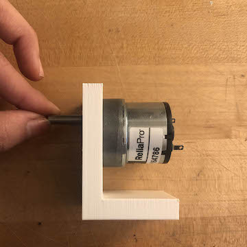
motor fits a tiny bit loose but not really a problem :
motor in holder and moving :
Even though the motor holder was not as tight as the bearing, it stays in place when turned on,
it should be ok, but I could make a bit tighter if I continue moving foreward w this motor.
wrong wheel but wanted to just see what would happen :
It moves!!!
Once I add the wheel, it's shaky, but the wheel isn't the updated wheel and I am still
missing the shaft that would correctly connect the motor to the wheel.
overall assembly :
Again, wrong wheel and still missing connecting shaft, but this is going to be general
assembly. Two printed l brackets one containing the motor, the other a shaft, and in between
a wheel with a shaft that connects both brackets. I hope to test the correct assembly tomorrow,
but for now its good to know the motor and the bearings fit correctly!
These pieces - I think - work as ABS printed, but if I wanted to get really fancy, I could knee
mill them.
10 / 25 / 19 : testing the correct wheel
right wheel / shaft fitting incorrectly :
Today, I got the shaft out of the acid bath - unfortunately, it didn't quite fit.
Rather than measuring the wheel, I went according to the dimensions on Amazon, and even though
they were right, the wheel tightens in the center, so the shaft couldn't go through the wheel
completely.
Additionally, the connection between the motor and the print had support material that didn't
want to desolve. Enough had desolved in order to fit the motor in, but as you'll see in the
video - the incorrect fit / length / support material the wheel is hanging a bit, unstable.
Ideally, the wheel would be supported at both ends, which is why I printed another L bracket
w bearing, but again, the shaft didn't fit, so I could quite test it.
incorrect fit, but wheel is moving :
Even though there is some adjusting to do, I think the wheel is a good fit for what I'm trying
to do.
In order to test if things could be moved by the wheel, I was placing objects on it and turning
on the motor, and sure enough, they were being pushed off.
Tomorrow, I will remodel the shaft and hopefully I can get a good fit sometime this week and
move on to testing the plate assembly / conveyor belt section.
10 / 26 / 19 : julio's belt close up
julio's full belt : (source : FRAME)
Today a close friend of mine, Khorshid, emailed me an
article on Julio's HBO special. In it, there were images of the conveyor belt, I had
never seen. I originally thought the belt was a full loop, but turns out its not, and it turns
out the plates are slightly curved, but you can't tell from the HBO special.
conveyor types :
Originally, I wasn't sure what type Julio's conveyor belt was, but it seems like it's a combination
of 2 and 3. In the images below, you can see the plates above and below the conveyor...
In any case, from the first image, you can see there is one big motor at one end of the belt.
I guess this isn't necessarily helpful since I'm not using a belt / curving plate, and I am
going to be using small though more motors, but I was super excited to see these images.
Another image was particularly helpful :
close up of the belt : (source : FRAME)
close up of the belt on set : (source : FRAME)
Here, you can start to see hints of the belt assembly (and the pedal that drives the belt).
In particular, I like the idea to add a kind of gap in the middle of the belt in order to be
able to add supports - as many or as few or maybe even none, if you want the belt to sit on
the ground.
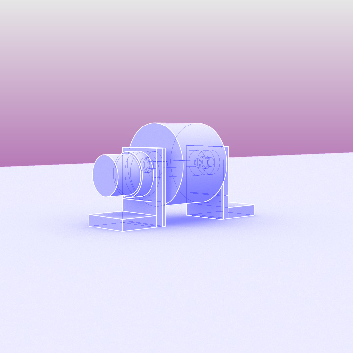
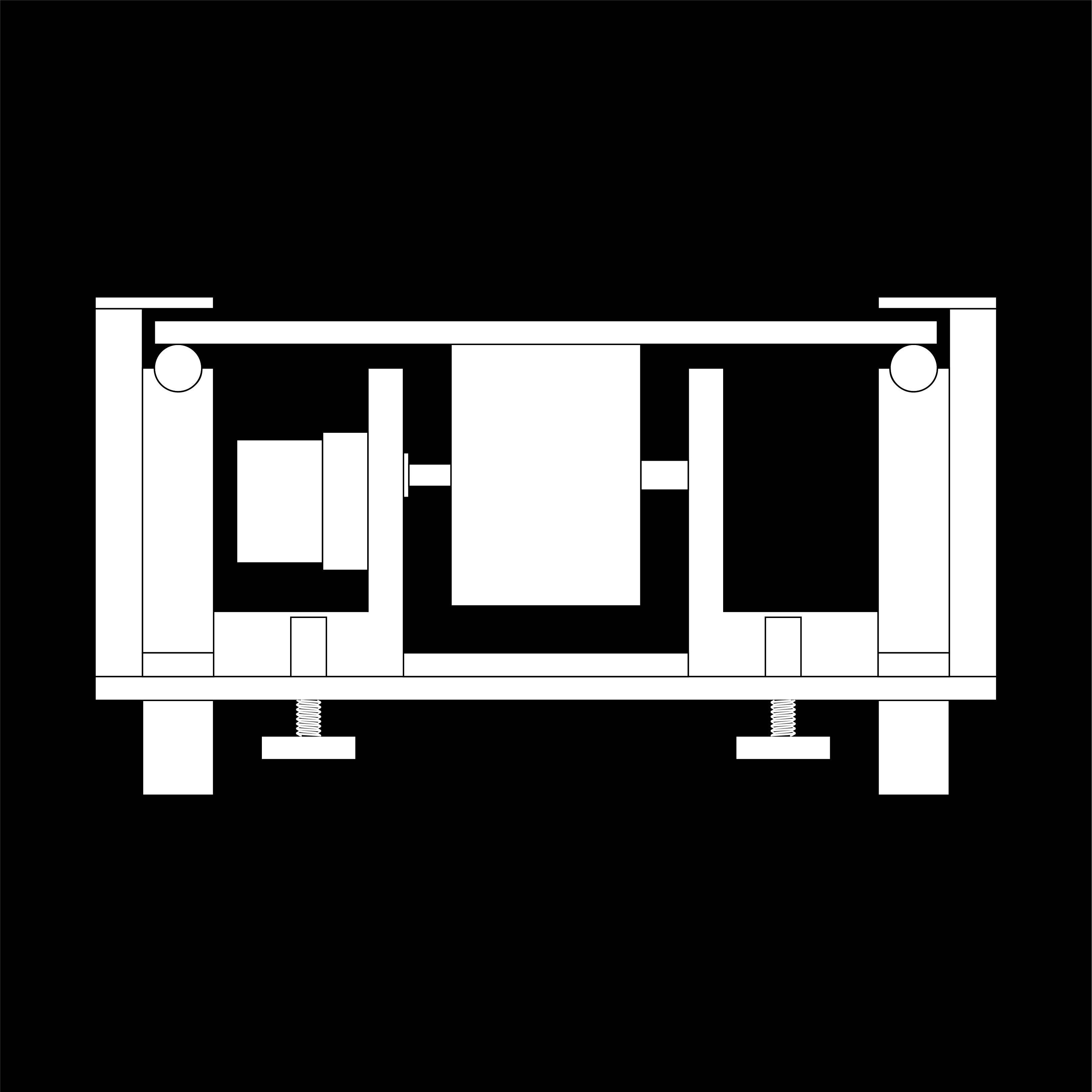
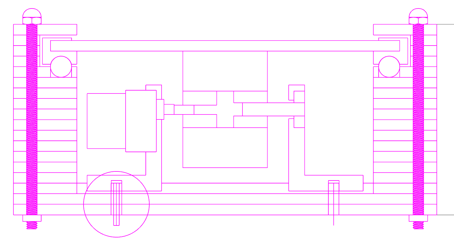
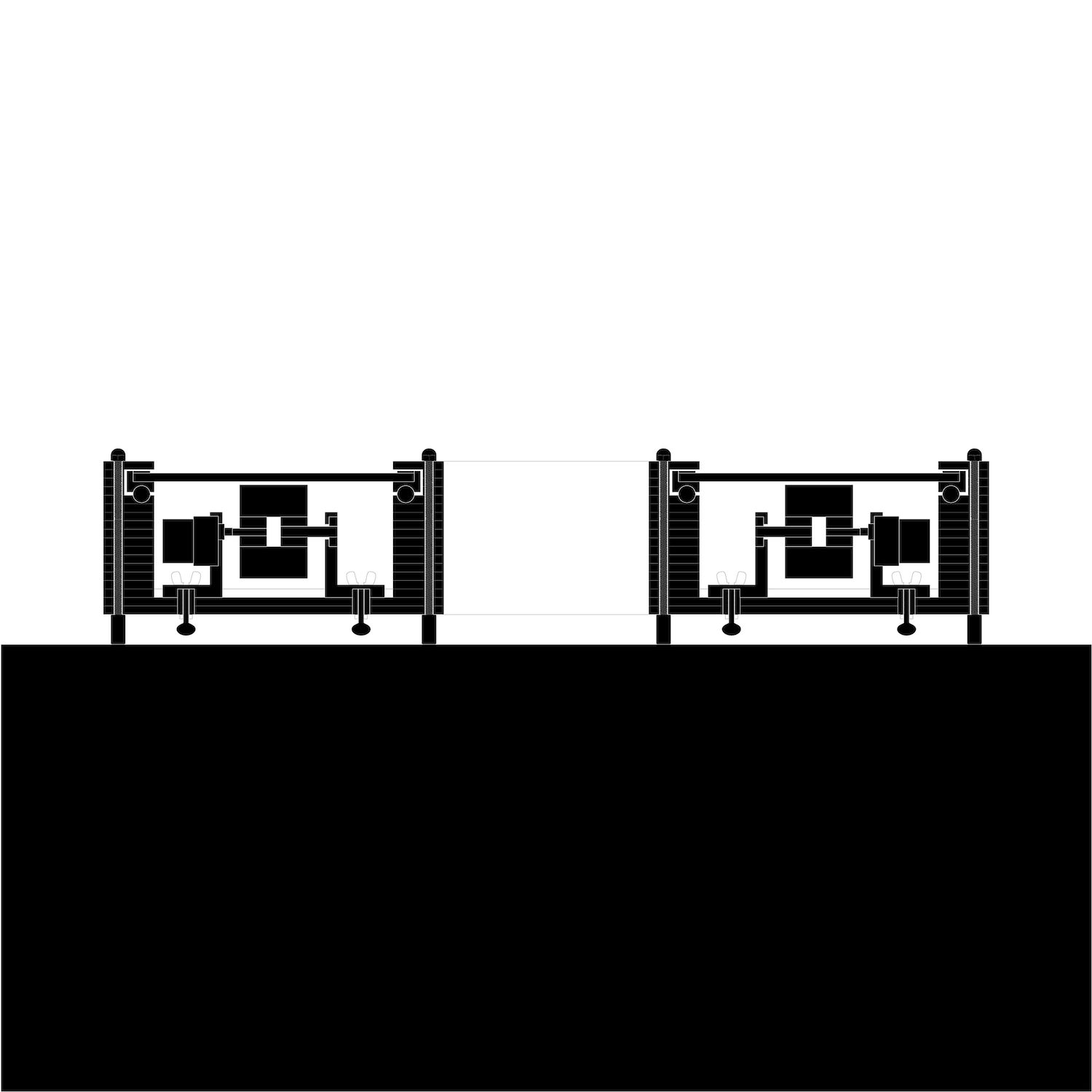
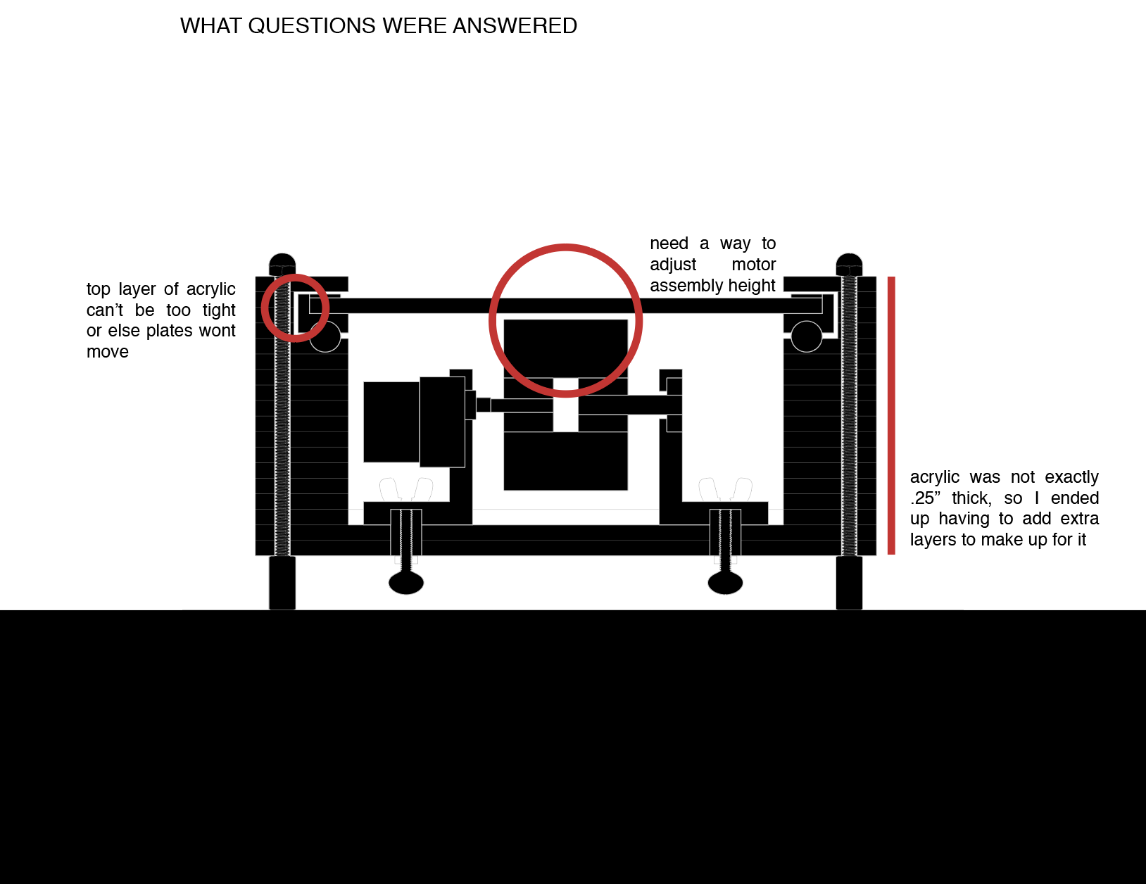
updated section to day :
For now, I have updated the section - after Anthony's input from last week.
No more stepper motor. And I've also added a height adjusting screw to calibrate the motor
height rather than rely on perfect tolerances.
You can see, I've located the motor I've been testing at the middle - this wouldn't exist
all along the belt, only, maybe, 4 times. However, the width of the belt (~9.5") is a bit
wider than I originally anticipated - though it is still quite narrow, which is what I wanted.
I've started to seriously consider how to make this belt. So, in the section, I've started
to try to draw things as they will be cut..
I have been imagining making this out of aluminum, but I think it's worth making some prototypes.
It might be more reasonable to make outer / visible aluminum, but to use other materials elsewhere.
As soon, as the motor is more or less working, I want to move on the testing these assemblies,
because I don't think they are functioning at the moment.
10 / 28 / 19 : aluminum or acrylic + color
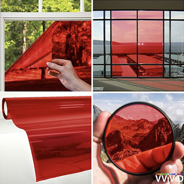
glossier show room for glossier you perfume :
red windows :
A combination of seeing Julio's belt close up (revealing non-aluminum plates, which I somehow
always remembered being aluminum) and looking through Glossier's show rooms for
WEEK 08 has me questioning whether the plates for my conveyor belt should be aluminum
or acrylic.
Because if they were acrylic, there might be a possibility to "color" the conveyor belt plates
according to the use / objects.
window tint purchased on amazon :
While I'm waiting for the motor / wheel 3d print corrections to print, I've ordered some window
tint (I think can be cut on the vinyl cutter). Maybe finally this week I'll attempt to cut
both acrylic and aluminum on the waterjet...
10 / 29 / 19 : scaled down version
original dimension :
I originally wanted to make a 6' conveyor belt, where 6' was the outer dimension.
After talking to Anthony a couple of weeks ago, he said it might be better to make a scaled down
version for this class, and then pursue a larger scaled version of it on my own, or in conjunction
with the scaled version.
new scaled down dimension : 4' outer diameter
This makes me feel a lot better, and seems like a smart choice for many reasons. Thus, i've
decided to pursue a conveyor belt whose outer dimension is 4'. I chose this size because I
will hve to do some milling, and I could potentially cut the conveyor belt out ot one piece -
at least its base.
At this size, I would still be able to fit inside the belt and discuss my favorite objects.
However, I do still plan to try to work on the larger scaled conveyor belt, as my ideas for it
continue to grow and I'm pretty excited about it :
unscaled version :
The 1:1 conveyor belt I want to make is 7' wide in its interior circle. A 6' exterior circle
is pretty tight especially when at the moment my belt has to be around 9.5" thick.
After discussing the idea with friends, they were like, "what about the back of house? who is
going to load all of your shapes?" Jokingly, they suggested to add a dumb stud wall through
the center of the conveyor belt, so that you wouldn't immediately see the shapes, and someone could
load and unload them from the conveyor belt in the correct order and I thought it was a great idea.
I suppose I am more closely trying to replicate Julio's stage. But I have this idea of creating
a kind of lecture series around it in which architects would create a series of shapes and
would lecture in this manner.
I was originally interested in the novel way in which Julio presented, so I think this is maybe
going deeper into my own interests / research, but alas - this probably wont get done by december,
so yes - scaling down i will.
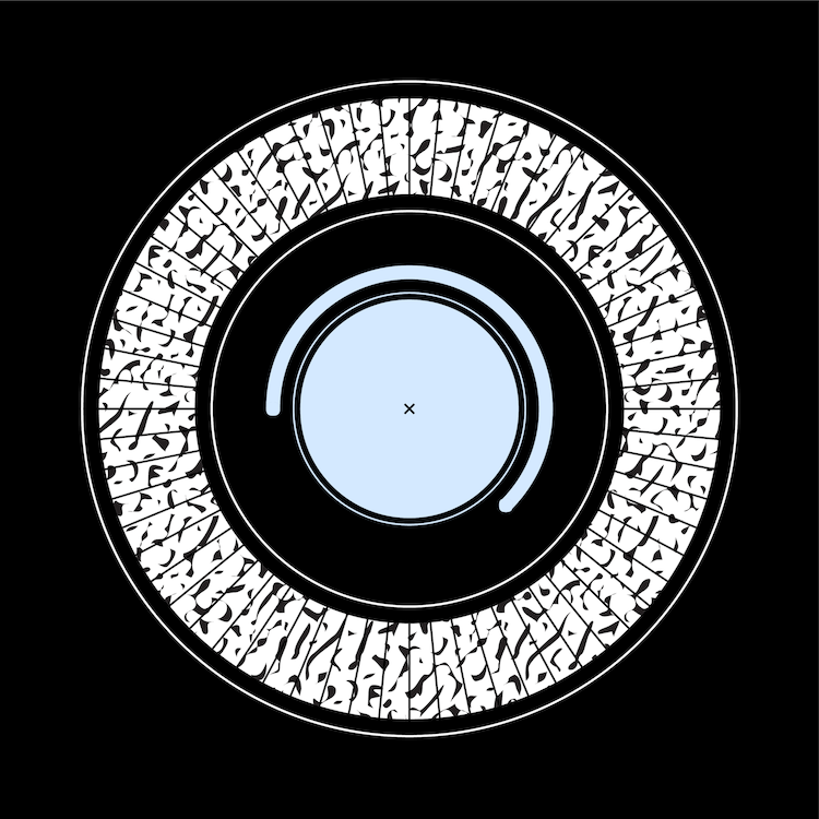
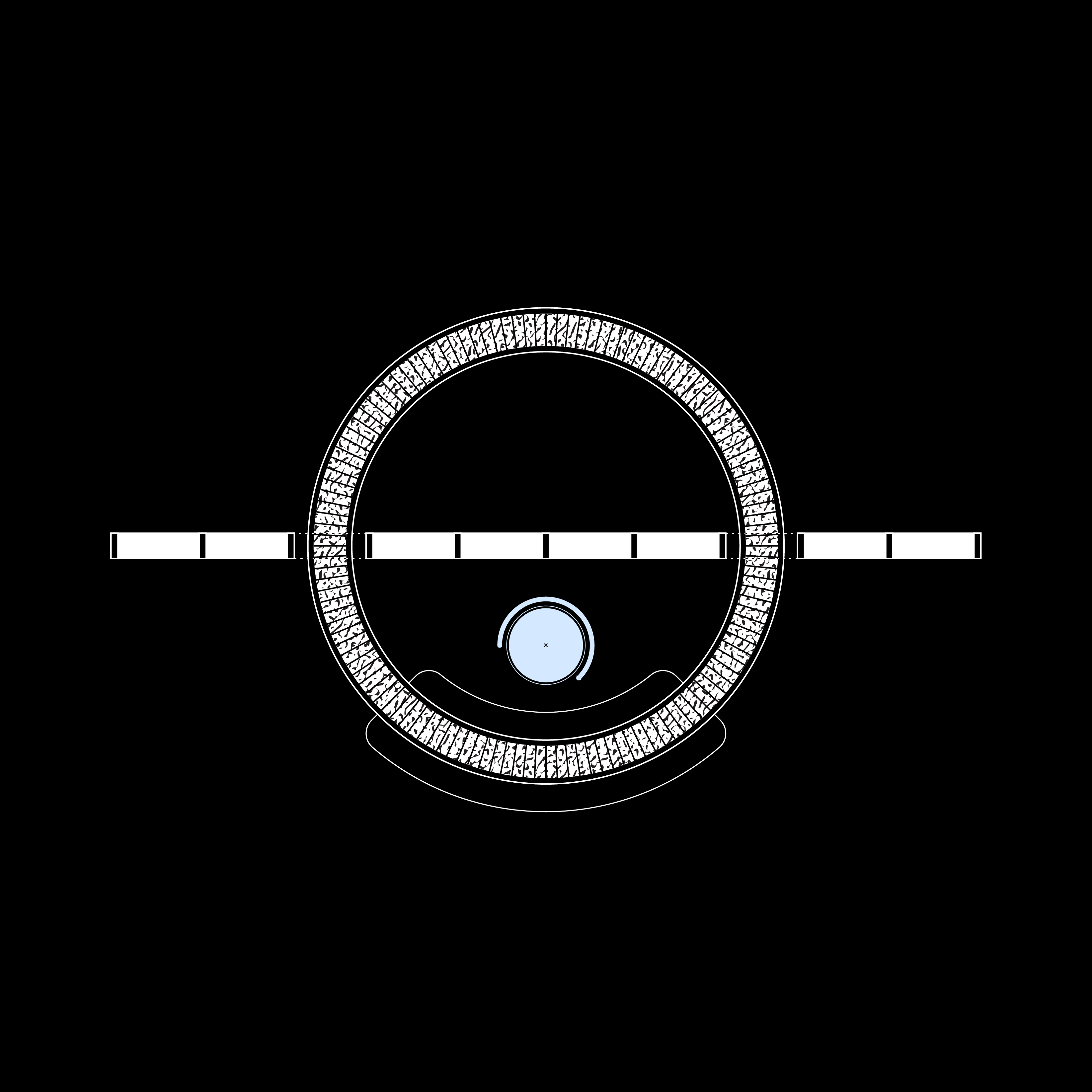
scaled compared w unscaled :
And here's a drawing that allows for a comparison for what I'll make for the class vs what
I hope to make soon after...
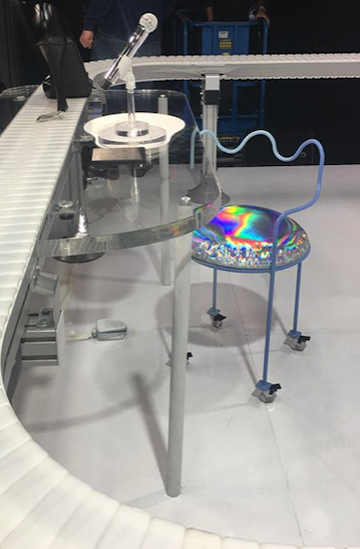
julio's chair :
btw that circle in the middle is julio's chair (a placeholder for now) - designed by his
sister,
marta.
11 / 01 / 19 : teflon, joints, and funding
Today I met with Diego to discuss my final project, which was super exciting and helpful.
redlining the current section / notes :
Here are a couple things we discussed - some reference the drawn over section above :
+ teflon strip under lip :
although, I've added a height / adjust screw in order to not rely on perfect tolerances /
and adjust the wheel as needed to put harder or lighter on the plates above,
the plates might
"jump" when they arrive at the wheel due to whatever slight change in height the wheel might
be at. Diego suggested
adding something that would push down on the plates as well - but
doing so in consideration of friction. The lip Paloma suggested a couple of weeks ago was
meant to hold plates in but not push down on them. So Diego suggested considering adding a
strip of teflon below the lip that would control the plate from any kind of jumping.
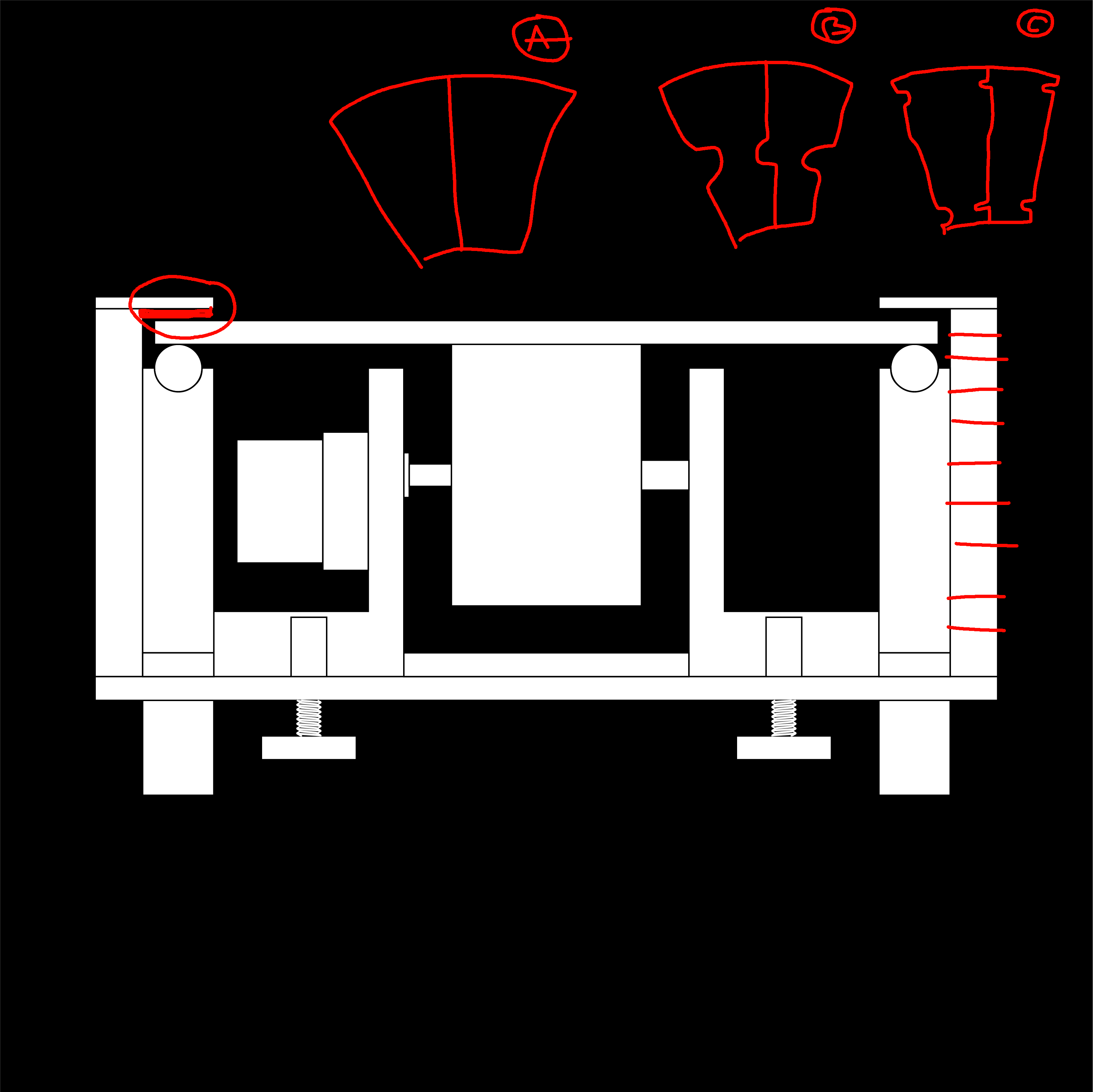
+ plate joints :
in order to
further alleviate jumping, plates might be "connected" - anthony had also
suggested this.. I expressed to Diego that I want the plates to read as "clean" as possible (A)
and that I wanted to keep away from having to mill plates - as there might be a version in
which there are MANY plates. We discussed there might be a nice way to incorporate a simple
2D joint that could keep plates aligned (B), but that I could also
push these joints to the
edges (C), so they would be hidden by the lip of the belt.
+ layered fabrication :
the fabrication of this conveyor belt is something i have thought about but have yet to address -
as mentioned previously, i want this to be aluminum but it might be smartest to jus make the
outer parts aluminum. Diego and I discussed possible
CNC most of the belt from lightweight MDF
or plywood. He strongly suggested combining parts as more parts required more tolerances to
consider. In making the 4' belt, although I could make it out of one piece (consider cutting
a 4' circle on the onsrud, i am going to force myself to make it out of two halves or four quarters
in order to learn and be able to apply this same logic to the ~8' conveyor belt. We agreed
I
should not depend on glue, but possible
mill some kind of registration points
and maybe
3d print pieces that would make sure all layers are aligning correctly.
+ prototype :
diego strongly suggested to
begin prototyping as soon as possible. Today, I will be receiving my
updates to the 3d printed motor from last week (there was a huge back up on the queue so even
thought I submitted my parts last saturday, I am receiving them a week later). I think once
this is more or less figured out, I will start water jetting / cnc maybe
a quarter of the
4' conveyor belt - as there are sure to be erros but I also
need a big enough section of it
to test appropriately.
+ funding :
I expressed to Diego that this conveyor belt idea is
hopefully going to at some point manifest
in a larger ~8' conveyor belt. I have an idea about creating a lecture series around the belt,
and diego strongly suggested looking at funding opportunities. He thought it would be great
to
make a successful 4' conveyor belt and use it to apply for funding to make the ~8' one.
These are the funding opportunities he pointed me to :
+
CAMIT Grant by Council for the Arts at MIT
$500
+
Bill Mitchell ++ Fund by MIT SA+P
up to $2,000
+
Harold Horowitz Student Research Fund by MIT
SA+P
up to $4,000
+
Keller Gallery by MIT SA+P
not a funding opportunity, but possibility of
exhibiting the finished conveyor belt
It turns out, the Mitchell and Horowitz applications are due January 3 - so this might work
out. Unfortunately, the CAMIT Grant for this semester has already passed - Diego suggested
I might apply to this one for funding for my 4' belt. But I am anyways, excited about this,
which I hadn't really considered before now.
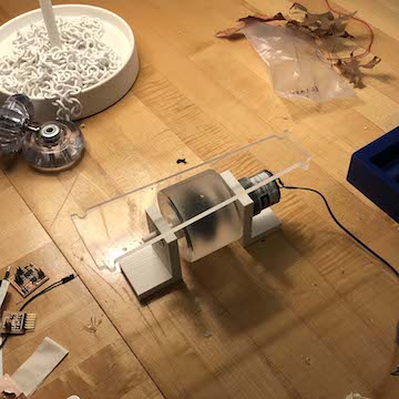
11 / 03 / 19 : motor assembly working
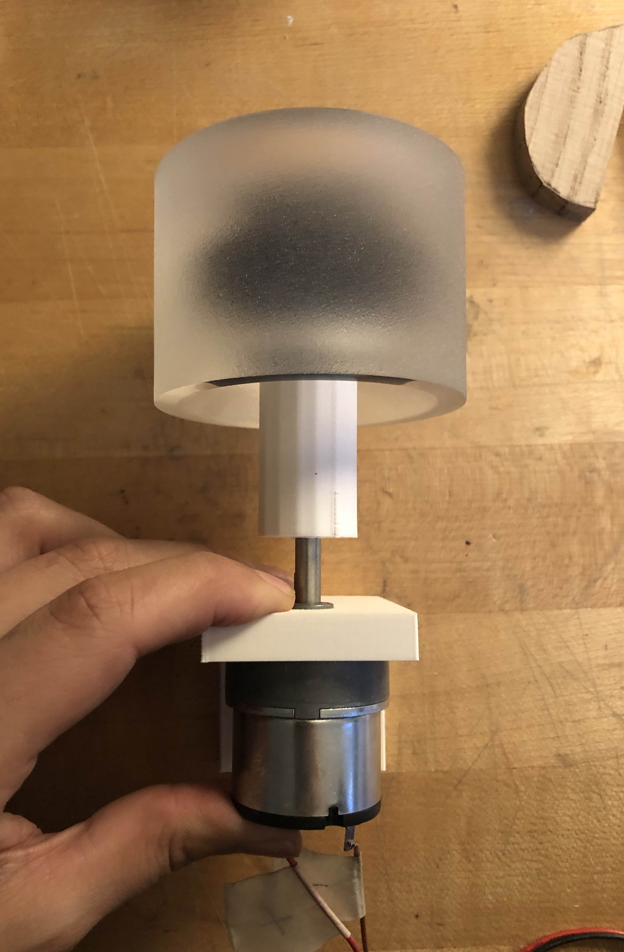
motor assembly prototype :
after a week of waiting for my corrected / updated 3d prints, i was able to re-test my motor
I started working on in
week 07.
I think I will resend to print one last time, but mostly to shorten things here and there. The
pieces are a bit tight so the motor, for example, it difficult to insert, but once inserted is
pretty secure. The rod at the opposite end doesn't want to enter the wheel completely bc of
tolerances, but again, the tightness is sort of needed, so I don't want to make this thinner
and wobblier.
screw detail needs to be added :
Ah - I will also have to add the screw heightener detail to the motor assembly since that
wasn't included at this point.
!!! :
The L bracket that holds the motor could be a tiny bit tighter - if you look at the video
below you can see the force of the motor moving sort of incrementally pushes it out of place
more and more.
I am super excited that this is more or less figured out - I mean, at least at this stage.
I'm sure I'll have issues once I start prototyping the conveyor belt, but this is v cooooooooool!
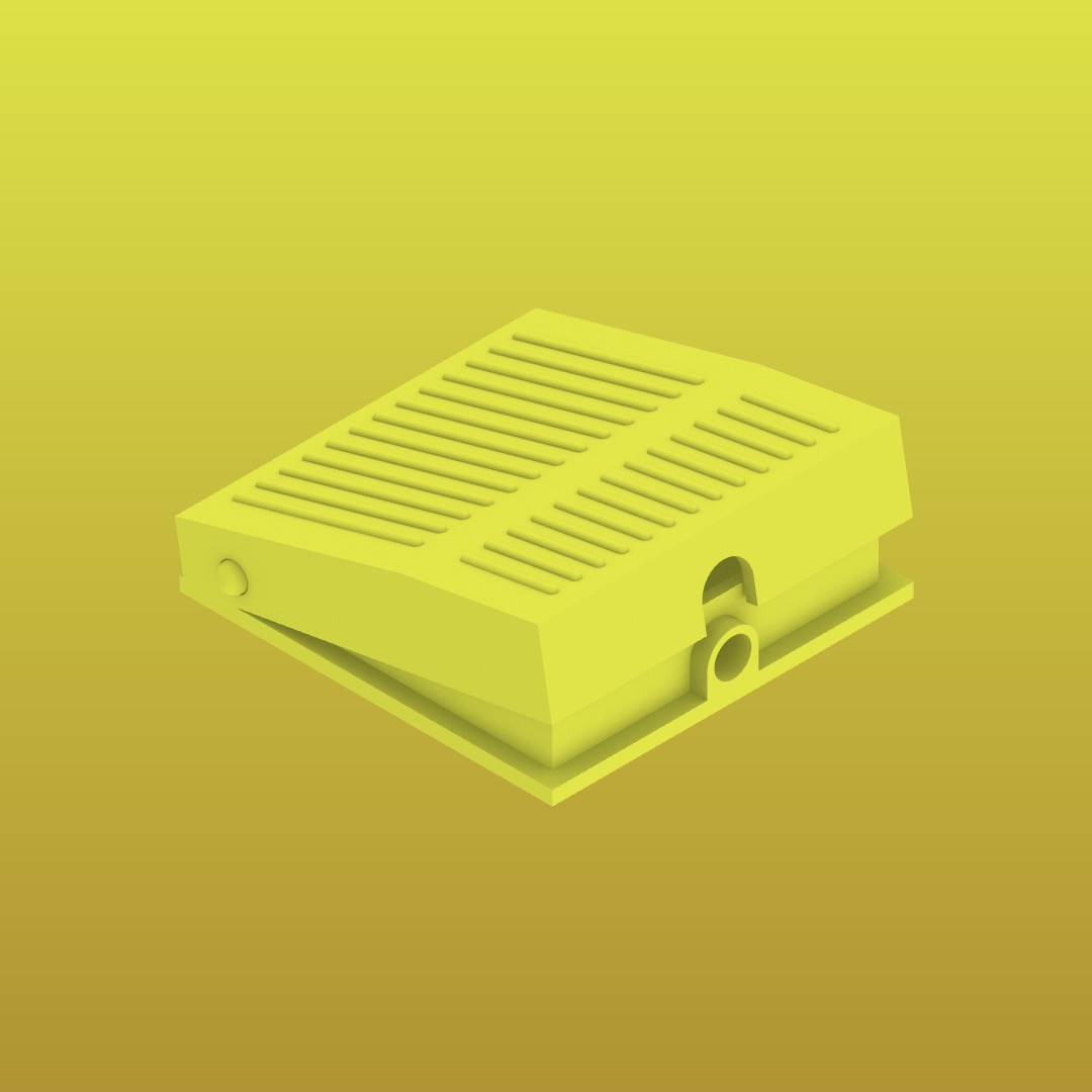
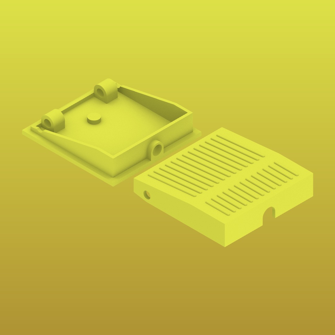
11 / 07 / 19 : push pedal prototyping
push pedal assembly :
push pedal parts :
this
week 09, we we asked to work on an input device. My final
project is pretty simply in terms of electronics, but i knew i wanted a nice push pedal to control
my conveyor belt. While my attempt to use step response via arduino ide was not successful, i was
able to 3d print a pedal prototype.
printed push pedal :
Ideally, I would want to make this a nice push pedal - I just wanted to test whether it would work,
and as is it is tight:
too tight of a fit :
Anyways, I wanted to make this out of aluminum, but I don't want to get ahead of myself.
Maybe I should just make a very nice spring loaded button - or a very tiny finger pedal.
11 / 14 / 19 : controlling a motor with a button
WEEK 09 was pretty rough. So was
WEEK 10.
However, by the end of
WEEK 10, into the next week, I was able
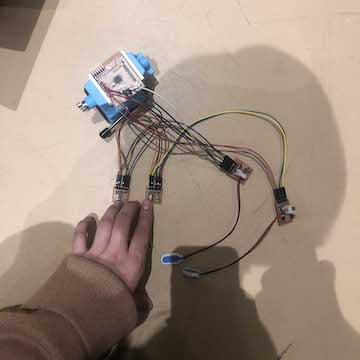
to successfully program a fabduino to control a motor with a button :
button controlling motor via fabduino + 2 breakout boards :
This is basically the extent of electronics I'll be using. I do want to make a very beautiful interface,
which I hope I can start to focus on in conjunction with beginning to prototype.
I will probably add the ability to turn the motor in the opposite direction, and for
WEEK 11
I will be using wifi. It seemed like the most possibly relevant to my project - so idk
would be kind of cool to be able to move the belt through a website if this conveyor belt
maybe became audience interactive (I have this fantasy of the conveyor belt being used to
have lectures, similar to how Julio Torres delivered his standup - so maybe audience members
could control the belt to point to specific objects! COOL).
11 / 15 / 19 : controlling a motor with two buttons
Today I milled two more boards : another button board and another motor board. I left my second dc motor
at home, but I was able to test controlling the motor with two boards.
I think I'm a little careless when it comes to hooking up these boards. I couldn't figure out why
my new button wasnt working and I resoldered and ever considered milling a new board. Turns out
I had plugged something incorrectly... Sigh.
Anyways, when I did finally connect everything correctly, it was very exciting (though I know it is
incredibly simple) to control my motorized wheel with two buttons :
forwards / backwards buttons :
I will say that things are starting to get a lil crazy.. So many wires everywhere. I do kind of
want to make a nice plate or circuit board holder to nicely orgnize everything. Maybe next week
I will finally purchase aluminum or just prototype the belt w plywood.. I need to do it! Idk
why I keep holding of. I suppose I am just barely able to be on top of weekly assignments!...
Here is the code i used :
11 / 17 / 19 : prepping prototype files
Today, I finally sat down and started trying to figure out how to make a prototype of my conveyor
belt.
One thing I had discussed with Diego a couple of weeks ago was that assembly would be important
to consider. How does everything line up? Glue? Alignment bolts? Etc...
So, for this prototype, I will making a quarter of the conveyor belt by milling .5" plywood.
I will be making the quarter out of two eights of the conveyor belt, but rather than make 2 separate
eights, I'll layer the pieces to "stich" them together.
I could admitedly make this conveyor belt complete (4'x4' plywood is not a problem), but
having the larger conveyor belt in mind, I do want to make I could in the future make a larger
conveyor belt.
This probably doesn't make too much sense, but I hope pictures of the assembly will clarify it.
plywood assembly :
motors and bearings added :
aluminum plates added :
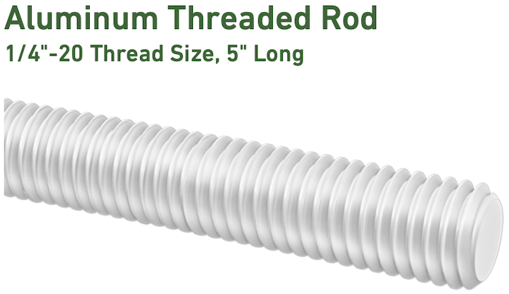
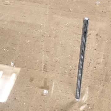
threaded rods added :
Like I said, i am not sure whether this will work, but I suppose that's the point. I did, however,
purchase some parts from McMaster that I think I will be able to re-use regardless of whether this
prototype is successful...
5" long alum threads :
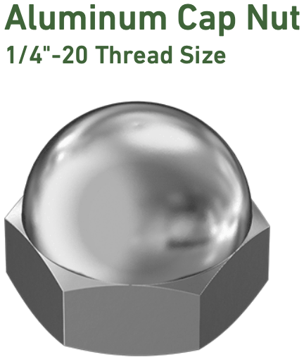
aluminum cap nuts - for the top of the belt :
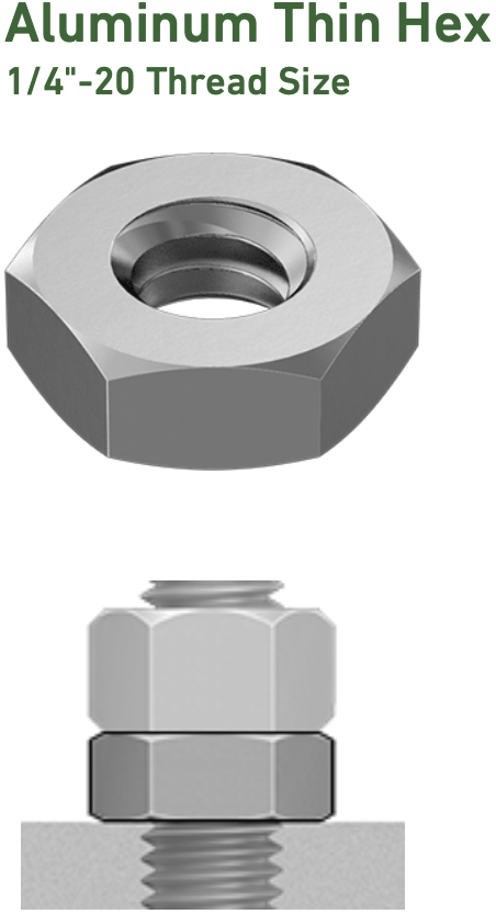
aluminum hex nuts - for the bottom of the belt :
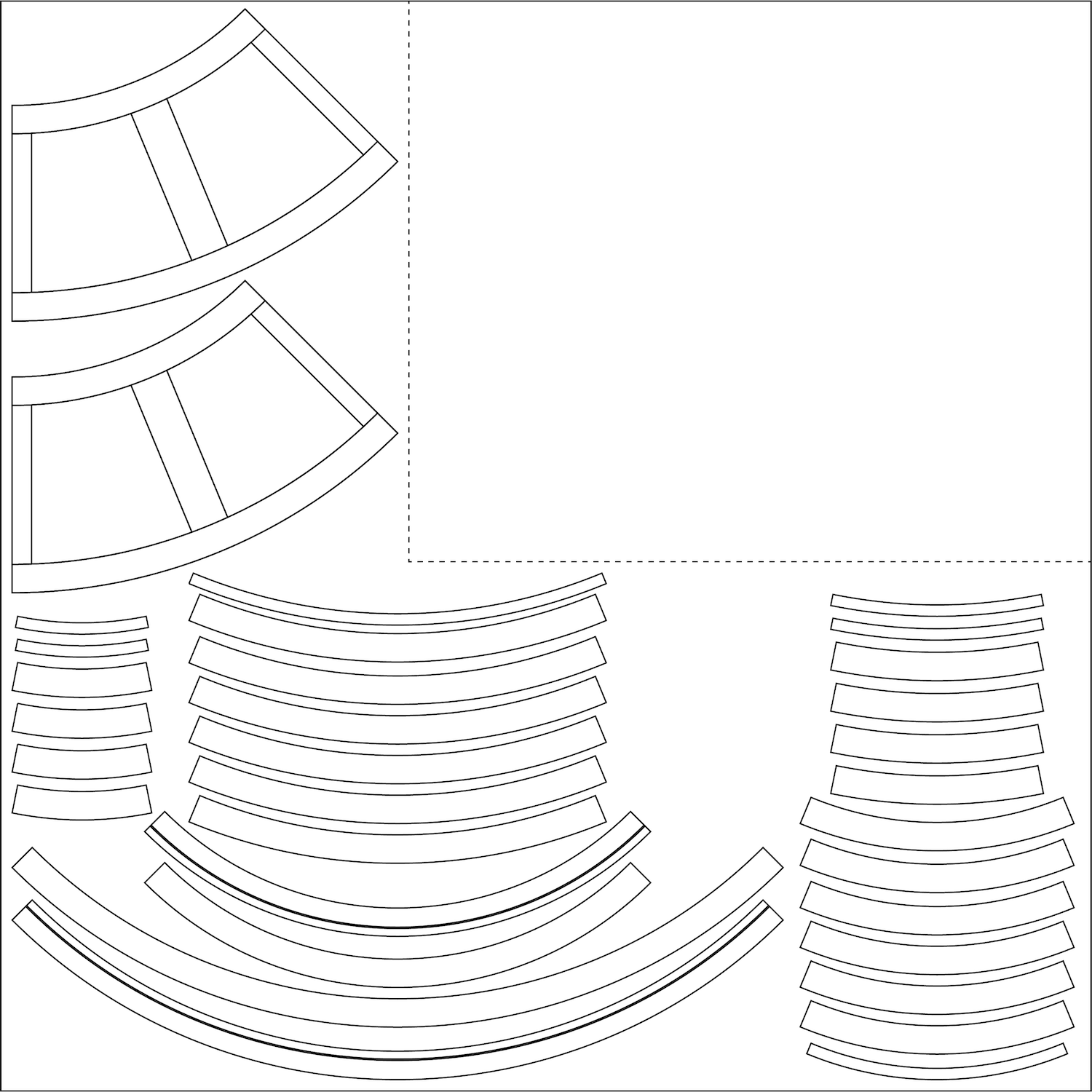
4' x 4' plywood cut sheet :
Before I set off to mill this, I'm going to measure the stock - soemthing tells me it wont be .5"
exactly, which will mess with my tolerances.
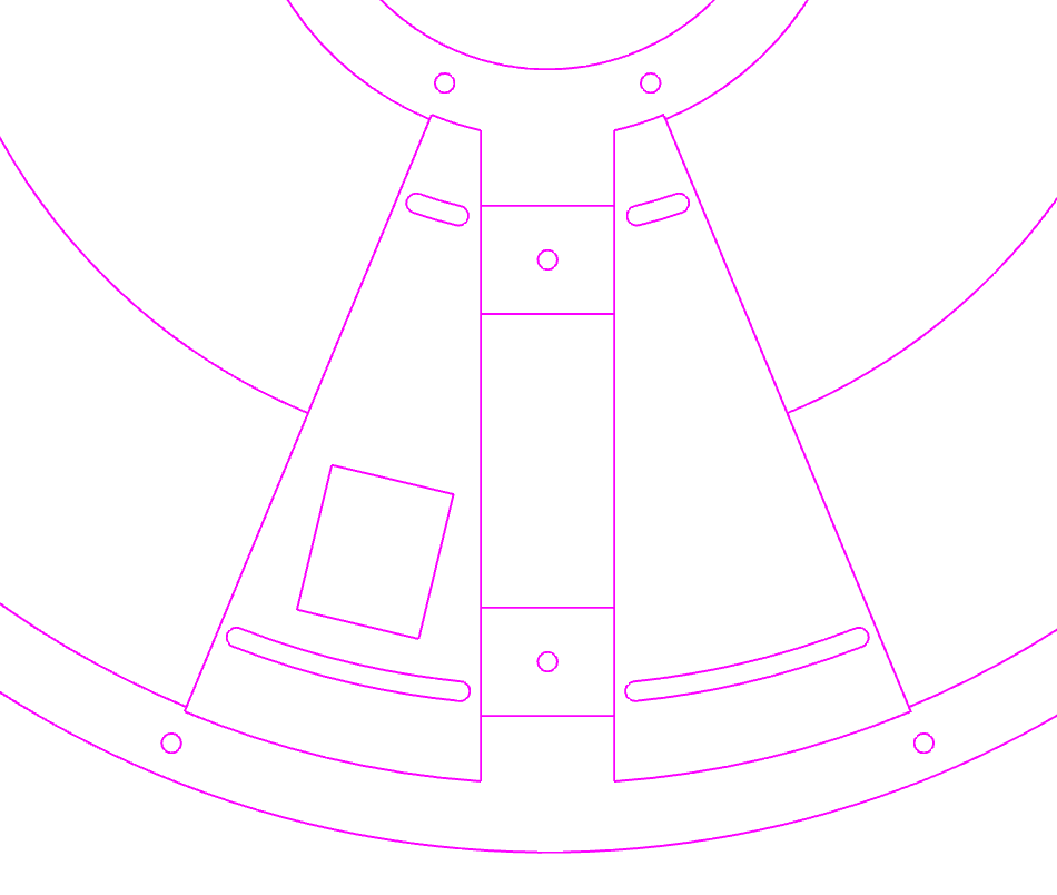
plates / new groove added :
in addition to milling the plywood, I'll be water jetting a quarter of the plates. I'll be testing
the kerf to make sure the plates are cut correctly.
plates / new groove added :
As you can see, I've added a groove to interlock plates - Diego and I also discussed this
during our check-in a ocuple of weeks ago. This groove wont be seen due to the "lip" on the
top most later of the belt.
11 / 18 / 19 : prototype redo
Today I visited the MIT Machine Shop as well as N51 to take a look at prototype materials.
Yesterday I started to set up files and discovered I would need :
+ one 4x4' sheet of .5" plywood
+ one 2x2' sheet of .25" aluminum
+ one 2x2' sheet of .125" aluminum
After visiting the shops, I found out aluminum is pricey, so I should probably hold off on it until
I know what I cut will work. These are the prices :
+ one 4x4' sheet of .5" plywood $55
+ one 2x2' sheet of .25" aluminum $100
+ one 2x2' sheet of .125" aluminum $50
Because I would be holding off on aluminum, I decided I would use acrylic - which I had mentioned using.
So, I took a trip to Altec Plastics in South Boston. There I bought :
+ 32" x 18" sheet of .25" clear acrylic $27.60
+ 32" x 18" sheet of .125" clear acrylic $15.00
+ 32" x 18" sheet of .25" red acrylic $33.50
After buying the material, I also measured it and of course it wasn't exactly the dimension it
was sold as.
As a result, I am going to remodel the prototype with the actual dimensions and try to pack
as much many cuts into the stock since it isn't cheap.
updated cut sheets :
a bit cleaner, a bit tighter, and some saved material!
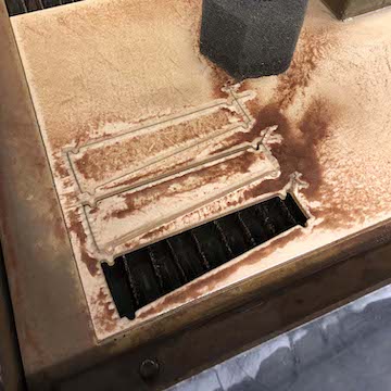
11 / 19 / 19 : waterjetting sum plates
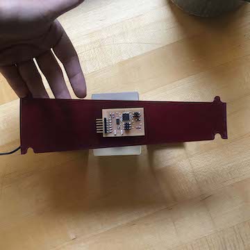
water jetting :
Today I met with Jung to cut some tests I had prepared. I had previously received training on the
OMAX but since I didnt cut a file, it didn't quite stick. Jung went over the basic set up and
help me cut a couple of files.
Most important things to note : When setting file up in OMAX layout, make sure you are cutting
on the correct side of your lines / You need space for lead ins and outs / Acrylic should be noted
on OMAX Make as low pressure + very brittle / Always set new z for material - note the difference
between setting z and going to z / water level should be .5" above the material / you can pause the
job and pull out cut material and restart job, but try to pause after lead out and before next
lead in.
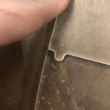
clean off before removing :
kerf ? :
It doesnt seem like there was much of a kerf. I will need to measure this, but I wonder if only
in this rounded portion there was a weird kerf. Visually this part will be hidden under the
lip of the belt, but I should make sure this wont affect overall tolerances.
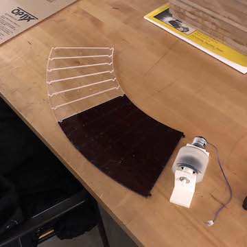
clear and red plate tests :
I cut plate tests in clear and red. I think I mentioned before, but I like this idea of a customizable
conveyor belt where whoever is using the belt might switch out plates to more meaningfully match
their curated objects. Altec Plastics also had yellow, blue, mint green, bronze, as well as
more opaque / non transparent colors.
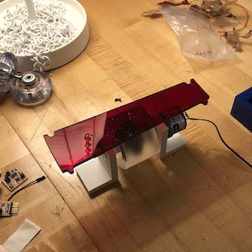
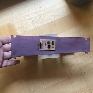
rich ruby red acrylic:
I love the red - it looks almost black when its sitting on the table, but with light, it turns a rich
ruby red. I think this color is dark enough where you wouldn't soooo clearly see the motor below, but
Jung mentioned I could sandblast the rest of it to create an opaque / non transparent look. I don't
think the motor below would be visible then.
plate to motorized wheel in clear:
See, I don't love the complete transparency. The insides would have to be really special / beautiful
for this to realllyyyy make sense. I think I will for sure sand blast the clear plates...
I suppose another option would be to add something right below the plates to hide the insides....
plate to motorized wheel in red :
Not as transparent / visible somehow...
sandblasted edges :
the edges of the plates are that opaque look I'm suggesting. You can't quite see through it.
I think this might be a good option for the clear but maybe also the red plates.
I need to measure whether or not there was a kerf because that will create a gap of sorts.
After measuring, it seems I need to offset the cut 1/128" to get a tighter tolerance...
Tomorrow I hope to set up the mill files in Mastercam and possibly mill after class or on
Thursday morning...
a moving plate :
for now it looks like the proportion of the wheel to the plate will work though - fingers crossed.
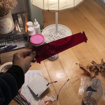
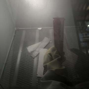
11 / 20 / 19 : sandblasting plates
clear :
red :
Today I wanted to see if I could lose some transparency by sandblasting the plates I waterjet yesterday.
I really don't want complete transparency because the insides of the belt have not been designed
to be super nice looking. I just think it would distract from the objects on the belt to be
able to look into it.
sandblaster :
The sandblaster is super easy to use. You flip a switch to turn on a light and vacuum and a push
pedal controls the airflow. It is a bit difficult to look into the sandblaster as sand builds
up on the glass. What looked like an even frost was quite uneven, once I was holding the piece
in my hands.
To that end, I wasn't sure if the sandblaster was needing more sand because at some points
it felt like there wasn't any frosting effect even though I was applying air flow to my piece.
In any case, I tried a couple of different tests. I tested both clear and red acrylic, and I
tried frosting one side vs two sides. here are the results :
clear tests :
Bottom two plates are sandblasted. Bottom plate is only sandblasted on bottom side, thus top
is still shiny / reflective.
clear frosted two sides :
clear frosted two sides :
clear frosted one side :
clear frosted one side :
red frosted two sides :
red frosted two sides :
Here you can start to see uneven-ness I mentioned. I doooon't like the red frosted on both sides...
The red acrylic is a super beautiful ruby red, but sandblasting makes the brilliant color kind of
disappear...
red frosted one side :
red frosted one side :
I like this far better than frosting both sides. Brilliance is still there but you cant see
the motor component beneath...
This is super exciting development...!
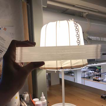
clear frosted two sides :
julio's plates for comparison :
I kind of like the frosted more than Julio's white plates...And this also is making me
consider - should I just make the whole conveyor belt sandblasted acrylic???...
stacked acrylic :
If I did that, the conveyor belt would have this kind of look - stacked sandblasted acrylic.
I mean, it would definitely be very different.. Visually very beautiful?...
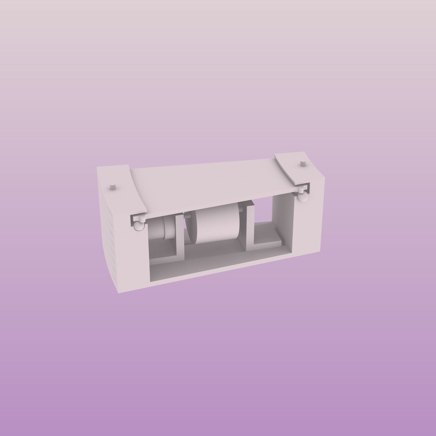
chunk model ? (approx 10" x 5") :
I'm thinking I should make some chunk models that would show what the belt would look like in
diff materials - one in acrylic, one in aluminum. Would be nice and not as expensive if I just
make a chunk big enough to include motor... It might also point me in a particular direction,
like, it might clarify what material I want to invest in.
Anyways - I will be trying to mill my cut file tonight or tomorrow morning out of plywood.
I prepped the Mastercam this morning. More soon!
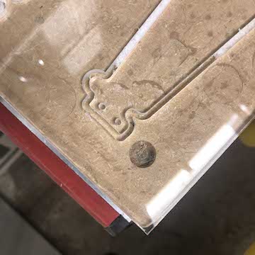
11 / 20 / 19 : milling a prototype
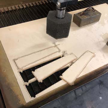
test test test :
So, I was able to mill a prototype tonight. Lots of mistakes. Lots of things learned. First
things first : i do nooooooot like the plywood at all! It splinters, you cant mill to the
specific thickness u want and have a nice surface finish, and honestly it just doesn't scream
"conveyor belt" to me. I want this to have a industrial or designy vibe and this is too diy.
I either have to really seriously look into how to hide the plywood, but as mentioned above,
I kind of am becoming interested in making an acrylic conveyor belt.. Is that a really bad idea???.....
kind of moves :
I became v aware of the fact that yes, the motor might not even touch the plates and
there needs to be a mechanism that makes up for the tolerances that cause it to not align.
I thought I could skip out on the height adjusting screw but its now clear I can't! Needs to
be added back in.
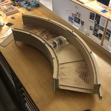
plywood is SO ugly :
I mentioned I could actually cut this out of whole pieces, but I wanted to understand how
to assembly a larger belt that might not fit into easily dimensioned material. So I layered
plywood and held everything together w rods I mentioned above from McMasterCarr.
The rods worked brilliantly, but I really should have made each layer piece contain at least
two holes for two rods. I cut things in a weird way that I didnt really think about and things
were wonky until I plaved pieces that had more than one rod. This is hard to explain... Simply
said each component should have at the very least two holes for rods to go through and align
things correctly.
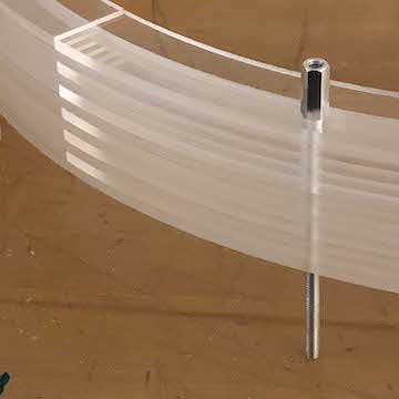
rod detail :
I was happy to discover the rod detail will work! and I actually really like how they look!
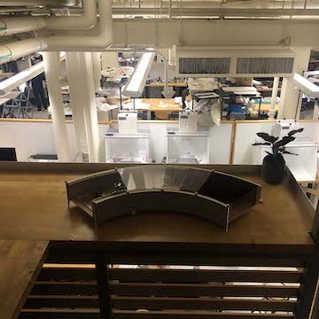
quarter of the conveyor belt :
Finally, I feel really good about the proportion of the belt :
you sit inside the belt :
I am hoping to be able to fit a person / a chair inside the belt to have the smallest
version of Julio's set up. I'm intooooo it!!
Lots of failures, but honestly, I'm glad I made this bc I learned a lot.
11 / 22 / 19 : rethinking a prototype
Today a close friend (and mit alum), Chantine stopped by studio to see what I was working on.
I didn't intend to ask her specific questions about my prototype but of course, she studied
mechanical engineering and so she had a few thoughts :
+ the only prototype that will help me see whether things are actually working is a completed
prototype. Chantine suggested I prototype the belt at a smaller scale because there was low
likely hood of me being able to simulate the plates moving (and pushing on eachother) via a
quarter model of the project.
+ the plates should be connected somehow and they should have a rail that places them on the
bearings - otherwise, its kind of a game of chance where the plates go, and if one plate comes
undone, they all will
warninggggg :
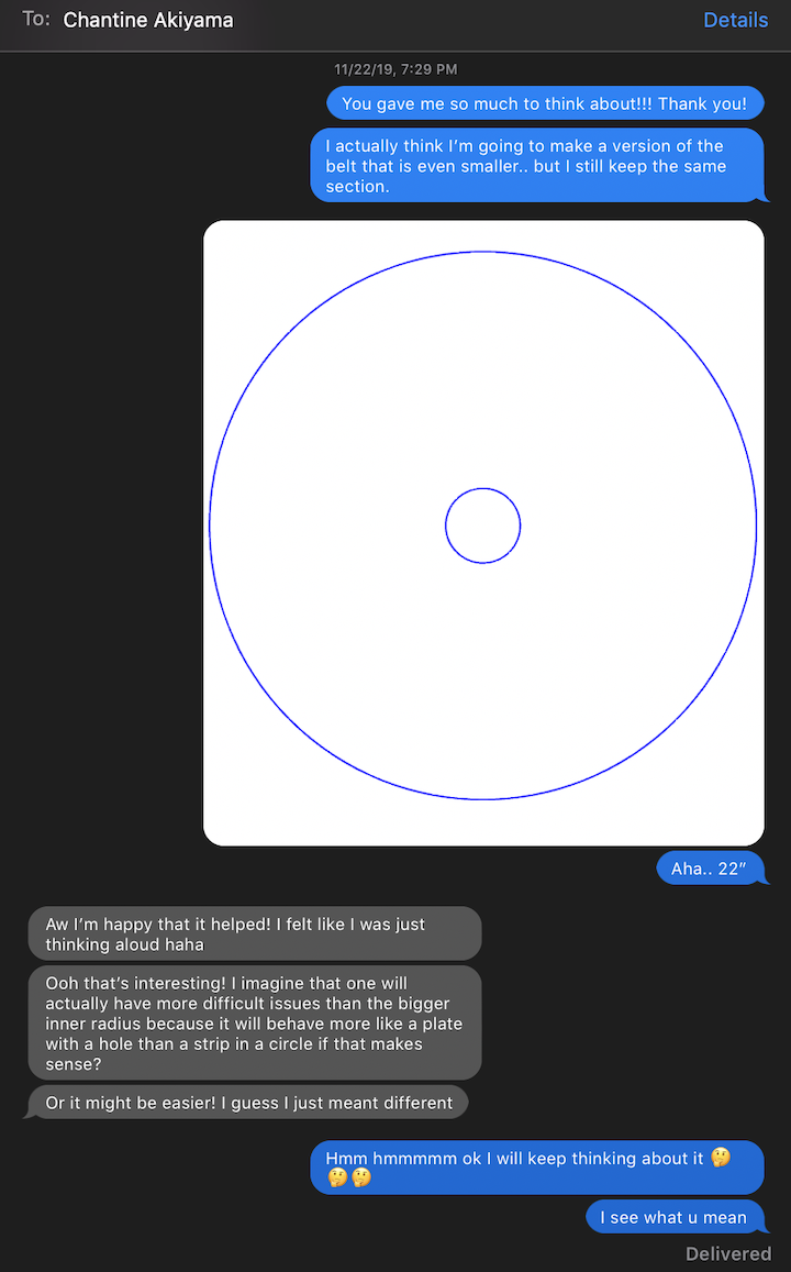
After Chantine left I texted her and told her I would make the belt as small as possible
(while still keeping the section as is ~9.5"). However, she told me to notttt make a circle
with a hole in it, which is
12 / 04 / 19 : smaller belt / protoype / final project?
I was stuck at the airport for 12 hours today, so I decided to flesh out what my next steps are :
sizing... :
ok - i keep doing this, but I STILL HAVE HOPE for a larger belt. I am really still aiming
for a 4'x4' belt, but I think it would be unwise to attempt to make a full scale at intended
materiality.
after speaking to chantine (my architect / mechnical engineer friend) - before machine week
craziness - she strongly suggested making a full conveyor belt.
Rather than make the smallest possible, I chose a bit bigger - Chantine suggested to also
not make a circle with a hole in it... So, I've decided to scale down to an outer diameter
of 26" with an interior diameter of 6". This belt will actually fit into my 4'x4' belt (on
image above the second belt is this size and the last belt is the 4x4 belt).
Decisions I've made for this prototype (which will possibly end up being the final project) :
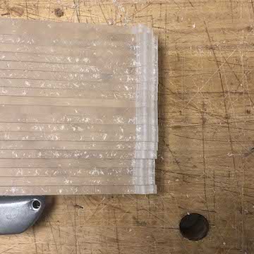
stacked clear sandblasted plexi :
clear sandblasted plexi :
+ it will be made of stacked clear .25 sandblasted acrylic
waterjet tolerance:
+ i will mill the acrylic in order to reduce tolerances (not sure how much the acrylic will
crack... if at all) (water jetting is still an option, but it wasn't as tight a fit as i had
hoped for. and when i compared to 3d file the tolerance changed throughout the piece, especially
in the connecting detail... this shouldn't be an issue if i mill it...)
"clear" wire :
+ i want to add channels in the acrylic in order to locate wires nicely throughout its interior.
(I bought this clear wire that might be a bad idea but I do really like how it looks and I
think it will look kind of nice w the clear acrylic...)
plate detail - connects and places on rail :
plate detail - connects plates :
plate detail - piece locks plate into place :
+ i will 3d print a detail that will connect plates and add a rail to the bottom of it
(this way the plate can remain a 2d cut out / easy to make / and the print will adjust it
to the belt.
height adjusting screw / motor assembly :
+ i will likelyyyy have to reprint or consider precision milling the small motor assembly
in order to accomodate for a height adjusting screw
flexible motor holder :
+ i will include a detail that holds the motor in place and creates a rail for it to be
made taller / shorter.
I think there was more, but I began to prep files to cut this asappppp (i do really want to
make my 4'x4' belt, so hoping I can make this one and confirm things are working and then move on).
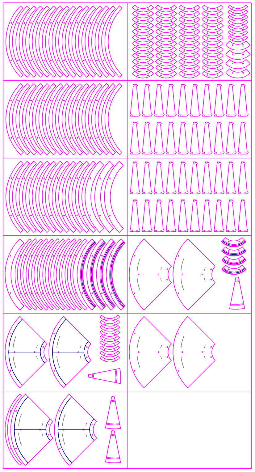
cut sheets! :
so far, I have ~11 cut sheets I need to mastercam... Altec plastics said a sheet around this
size is about $30, so I'm looking at ~$300... ! I'm cool w it. I'm investedddd at this point!
Artist supply said they would price the sheets at 24.65, but I probably wouldn't get until
next week, so I don't think that will work for me.
More soon.
12 / 07 / 19 : details figured out
last few days have been slow, but files are ready to be milled and i picked up the acrylic
tonight.
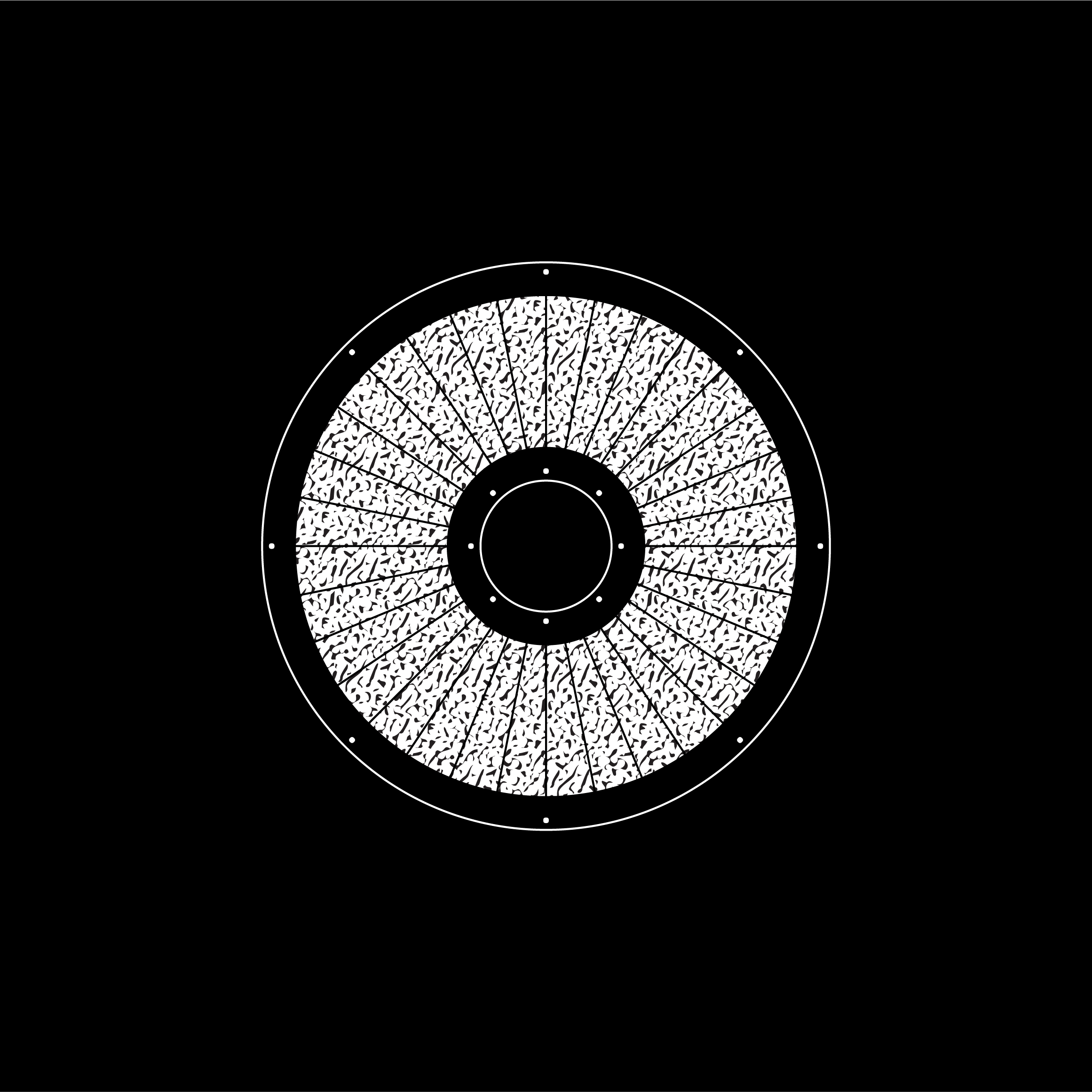
outer diameter of 26" / inner of 6" :
final-ish section :
final-ish section :
12 / 09 - 14 / 19 : milling / sanding / assembling
This past week has consisted of milling acrylic, sanding acrylic, and assembling acrylic.
Many things have been learned - mostly that I shouldn't have tried to pack acrylic sheets
as much as possible because the mill did not like that. Its better to add generous space
between pieces in order for things to not move and throw away a completely useful sheet!!
Milling acrylic meant a good handle on tolerances, but it also meant a ton of finishing work
post milling. Sanding took a forever and a toll on my fingers, but ultimately, I'm really
happy with the result.
no cracking! :
Initially I was worried about the acylic cracking, but actually that never happened.
hardware fitting :
As I milled I would double check hardware I purchased was actually fitting where it should.
edges needing sanding :
After milling, I would spend a good amount of hours sanding off onion skins and melted bits
of acrylic
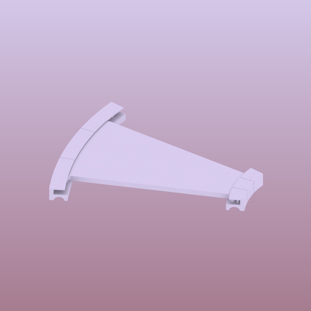
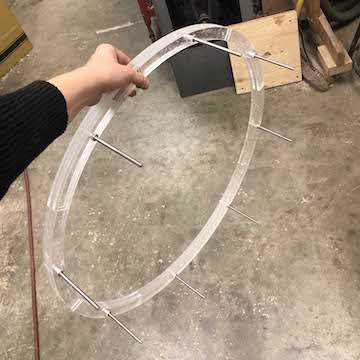
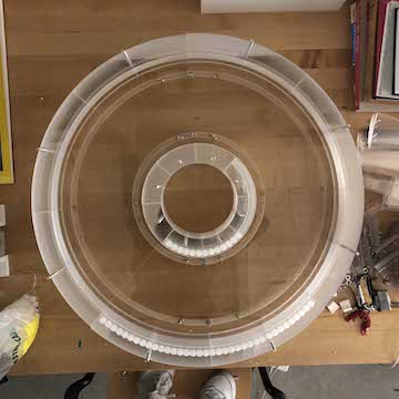
one piece :
I actually wasn't 100% sure that the assembly I chose would even work. Technically, I could
have found a way to make the conveyor belt out of complete circles, but knowing I wanted to
try to make a bigger version in the future, I wanted to use this as a way to test details I
would ultimately use in a bigger version. So each layer is made of four pieces and I would
alternate them so as to sandwich in pieces and connect them into one piece vs four separate
pieces.
plate tolerances :
I didn't actually think I would have an issue with the plates, but I actually maybe struggled
the most with them. I ended up removing the curves connecting detail (I decided the 3d prints
would connect the plates and this detail was repetitive). But even when I removed that detail,
the plates were far too tight and the last plate simply didn't fit. I realized I would
have to add a small space between plates to make sure they all fit. THis meant two sheets
were kind of thrown to the trash, but that was the point of making a smaller "prototype" right?
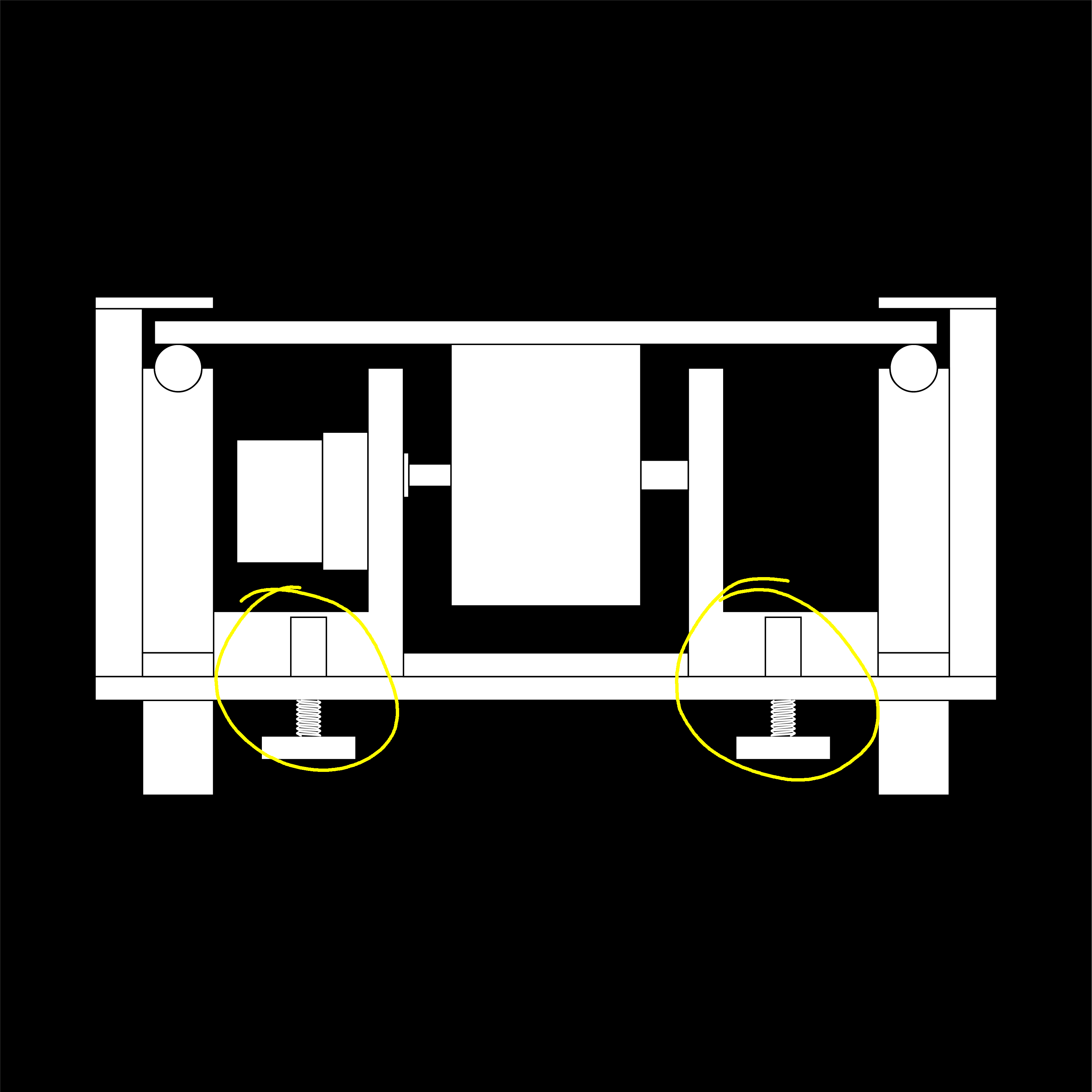
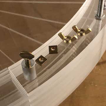
lil leg details :
I should mention, I really wanted to try to make a beautiful finished object, so I chose to
work with materials that were a bit more expensive.
Most of the hardware I chose was either aluminum or brass and it was all purchased on McMaster-Carr.
These long nuts I chose to use as the conveyor belt's legs. I had to do this because of a detail
I added that included a thumbscrew to adjust the height of the motor. THe thumbscrew was quite big
and wouldn't have fit underneath the belt, so I had to add some height. I was NOT excited about
this detail, but once I put them in place, I was super pleased with how it looked. It is one of
my favorite details, actually.
other McMaster-Carr details :
These are some other details - the bronze are all associated with the motor assembly in some way.
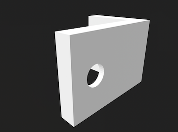
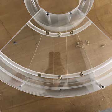
rail ready to receive prints :
expensive out of house prints :
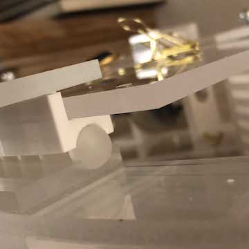
close up of the detail :
I mentioned in an earlier post that a mechanical engineer friend mentioned I needed a detail that
would connect the plates to one another and align them to the rail of ball bearing beneath them.
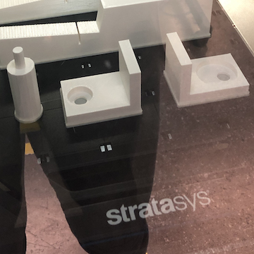
I sent these 3d prints to test during wild card week but because most of core was busy producing
for final reviews, the queue was to the brim. I was not sure I would get my test, let alone the
33 prints I needed. So, I decided to order a set of 10 to Stratysys. This was SO expensive!! But
the prints were actually really beautiful - they were clear and really went along w the acrylic
conveyor belt. I ended up being able to print the rest of the prints at school, but they were
obviously not as nice!
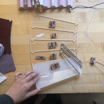
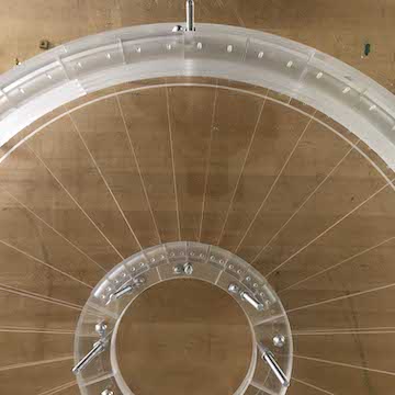
plate assembly working :
Everyday I would mill / sand / assemble, and it took foooorever to finally get to the rail
that would hold the bearings. In hindsite, maybe I should have cut this first. But once that
was cut and sanded (which by the way the curved rail was really terrible to sand, there probbaly
is a way to test that the ball tool leaves a smooth finish), I filled with the ball bearings and
tested the prints with the plates! And it workkkeeeeedddd! I was so relieved!
how motor is held in place :
Learning from my failed plywood prototype, I knew I needed a flexible detail to hold the motor in
place. One thing I've learned throughout this whole thing is that TOLERANCES MATTER! So
I designed some plates that can tighten around the motor via wingnuts!
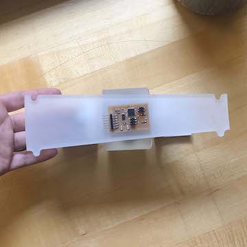
missing parts but kind of complete :
I had to recut the plates and this also took some testing. I needed to add some space for the
plates' holes to actually be able to receive the 3d print. The corrected plates were one of the last things
milled.
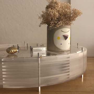
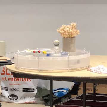
filling it w my favorite shapes :
at this point, I started to get pretty excited and placing objects on the belt, which is ultimately
what the conveyor belt is for.
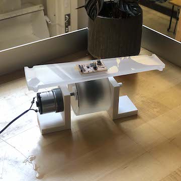
first test! :
While I waited for the rest of my prints, which were currently printing and still needed a
lil acid bath, I decided to figure out the motor height and wire up motors in plate.
Ideally, I wanted to remill the motor assembly out of aluminum stock I had purchased, but
I just didn't have time. So because the 3d printed motor assemblies didn't include the
thumbscrew detail, I decided to stack pieces of paper to get the motor to the appropriate height.
Surprisingly, this worked, haha.
Once I was at the correct height, I tried it, and we got movement!
I will note that the belt seems to - at the moment - work best with heavier objects.
This is something that was mentioned to me by various people. I think another issue could be
the wheel isn't stickiy enough. A friend suggested adding rubbber bands to increase friction,
because the semi smooth wheel on the smooth acrylic would sort of cause the wheel to slide
past the plate, not grab it and push it. For the most part it does move the plate, butttt
I would prefer a more consistent push. Of course, this will change once the plates are complete
and both motors are pushing on the plates, but I can't test that just yet since I don't have
all the parts.
heavy things work tooooo! :
Before I left for the night, I tested a much heavier object, and this also worked. I can't wait
to test the belt with both motors and all 32 plates! But this means the belt wont be completed
until the day before the final review, haha. WOops.
12 / 15 / 19 : prepping presentation
Today I decided to not go into school. I've been working on this project for one week straighttt -
and my hands needed a rest. I also needed to prepare the final presentation for Tuesday.
Here are some useful bits of information!
lessons learned :
Tolerances mattered a lot in this project and this is where they mattered most!
cost : $600.00
Though it was a bit complicated to look through receipts back from the beginning of the semester,
this is approximately how much was spent. This does not include the out of house prints, but
those were $200 - yikes.
Again, I'll mention here, this probably could have been done for much cheaper, but I wanted to
make an elegant object that had a finished look.
how project was evaluated :
I mean obviously this project was evaluated by whether it moved or not and what kinds of objects
it can move. At the present moment, with uncompleted plates, the conveyor belt moves, but not
perfectly. I imagine a second motor will help (I don't have enough 3d prints right now to
be able to test both motors).
I will say, one thing that would have helped or will help would be
a stickier wheel which was suggested by at least two people! But I didn't quite have the time
to rethink the motor assembly, though after this is will try to incorporate a new wheel I
cast out of rubber.
12 / 17 / 19 : presentation
Today was the presentation, and when it was my turn to present it was kind of a disaster.
Last night was the first night I was able to test the full belt, and it was not 100% working.
Initially all of the 3d prints were too tight, I'm guessing causing too much torque and the
motors weren't happy - the belt wasn't moving at all. So, I decided to cut down the prints
to add some space - because the belt was moving quite a bit before the belt was completed.
After I did this, the motor was moving. And it moved even more when there were heavy items
placed on the belt. So, I'm guessing the wheel isn't gripping the plate enough to move it on its
own. I did try adding rubber bands to the wheel to grip the wheels more but this made the wheel
too sticky so the motor would flip out of place - this might resolve if the motor is held down
better in place.
In any case, I was anyways pleased with the amount of movement - I wasn't sure if the thing would
move at all. So It was great that it moved, even if it didn't move a full circle. But when I presented
to the class, I put too much weight on it causing it again not to move at all. After my turn
had passed, I removed items, and it was functioning as it had been.
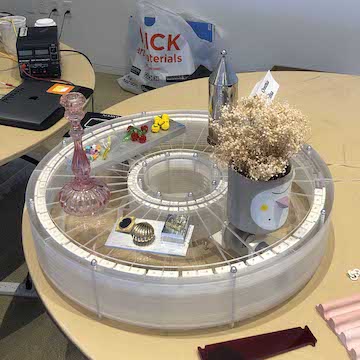
The open house was kind of the highlight of the day because people were in fact impressed by
the belt. They thought it was kind of a difficult but interesting problem to try to make
a beautiful transparent conveyor belt. And many people more well versed in mechanics or electronics
made really helpful suggestions of how to get the thing fully working.
Here are some videos / images of the open house :
too many of my favorite shapes / too heavy :
less objects - moving and "working" :
movement! kind of! :
messy wiring :
Neil commented that the wiring needed to be cleaned up, so I figured I would do my best tomorrow.
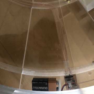
12 / 18 / 19 : post wire clean up
Today I came into school and cleaned up the wiring. I had milled some rims into the conveyor
belt in order to be able to nicely place wiring. So I located the motor break out boards next
to the motor / wheel assembly :
breakout board in belt :
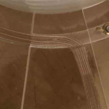
channel milled for wiring :
clean wiring :
I gathered the wires nicely. I had to leave home for the break, but I had printed a 3d pedal that
the button / board would be incorporated into :
channel milled for wiring :
and thats it! that's how i made almost anything!