This week was just too hard! I had zero knowledge about electronics and just understanding what to do took me too long.
I started from downloading EAGLE and reading almost anything the TAs linked to. I have read Molly's page and also
Sigridur's and Jacky's.
Although I still don't understand electronics in any way - I will first write what I did
to maybe help other architecture dummies like me.
1. Download Eagle.
2. Download the FabLab library for Eagle. This will have all the components you need for the HelloWorld board.
3. Download also the design rules file.
4. Copy the files to the relavent folders of eagle on your computer.
5. Open Eagle.
6. Creat new project and name it.
7. creat new scheme file.
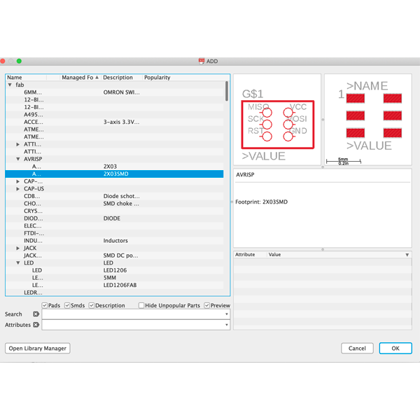
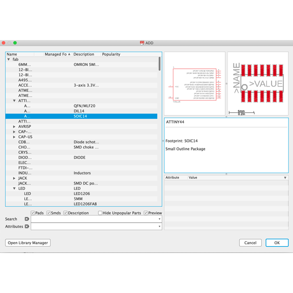
8. Open the fab library and enable it (green dot next to the name of the library name).
9. If you know nothing about electronics, you will probably won't have any clue how the components called and how to find them. THAT'S OK!
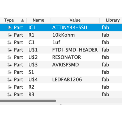
10. To know how to find the components I questioned the TAs. This is the list of the components and how they called (add it using ADD command):

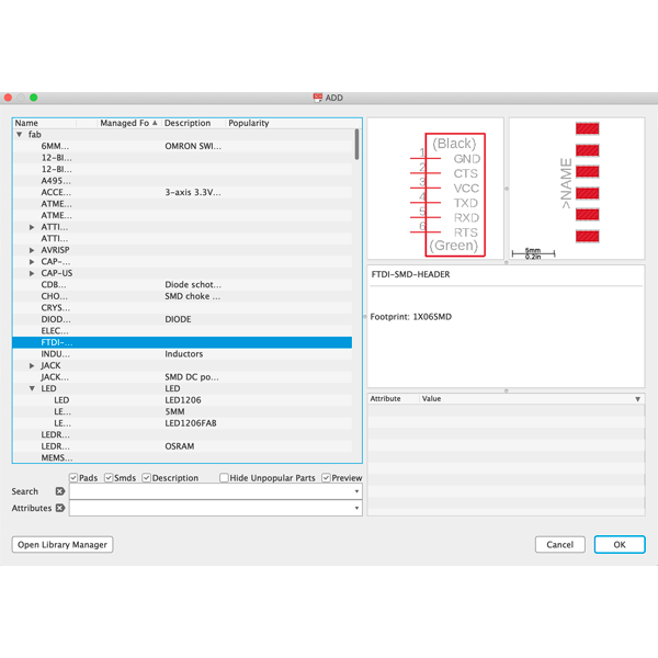
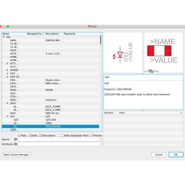


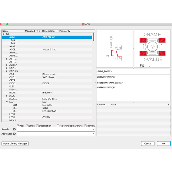
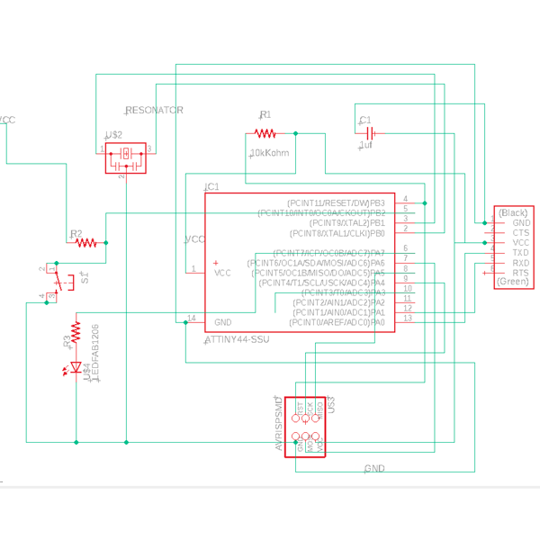
11. After adding all the components, I connected them by neil's board figure (besides the Led, two additional resistors and the switch).
12. Anthony the TA suggested to name the wires by their use and then you don't get a mess (for example, call all the VCC wires VCC, and they will merge).
The naming tab is on the left Eagle toolbar. (not a must!).
13. Now add the switch and the led. How? For the Led: I attached one of the available pins on the microcontroller (ATTINY) to a resistor and then the resistor
to a LED and the LED to GND (it can be any gnd on the board, they are all conected).
The switch: wire a resistor to a VCC and the resistor to the switch and the switch to GND from the other side. I wired the junction between the resistor and
the LED to an available pin on the ATTINY.
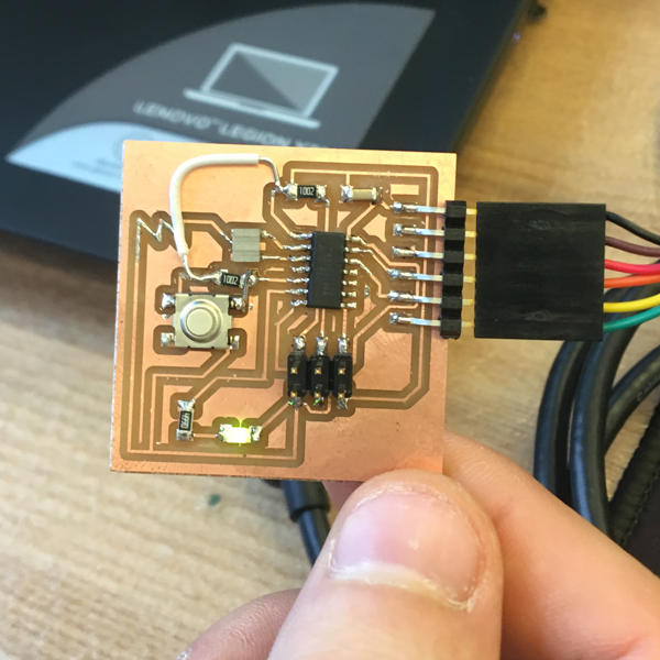
*** At first I did it wrong so I needed to add a jumper after soldering ***
14. Switch to board mode.
15. Load the design rules that you downloaded.
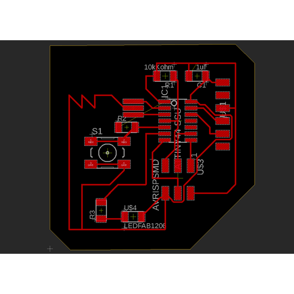
16. Now design the traces. That was the fun part.
17. Change the artboard size to fit your board using the move command and press the edges.
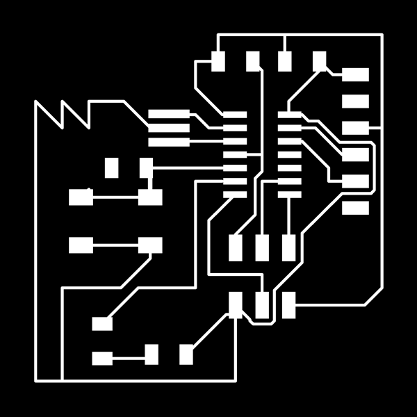
18. Export as image. Be sure to leave on only the top layer and cheack the monochrom box. I exported at 1000dpi.
19. I have no idea how to export the outline of the board to cut. I did it in Photoshop.
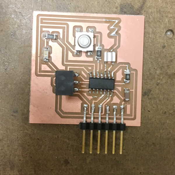
20. That's it - you ready to mill and solder!
***NOTICE that my scheme is a mess and the board doesn't show the bridge i had to add later!!!***
I had two problems:
1. I couldn't find the Roland in the devices. Restart of the computer solved it.
2. The first time I tried to mill the board was double scale. I changed the dpi in the MODS to 2000 and it worked.


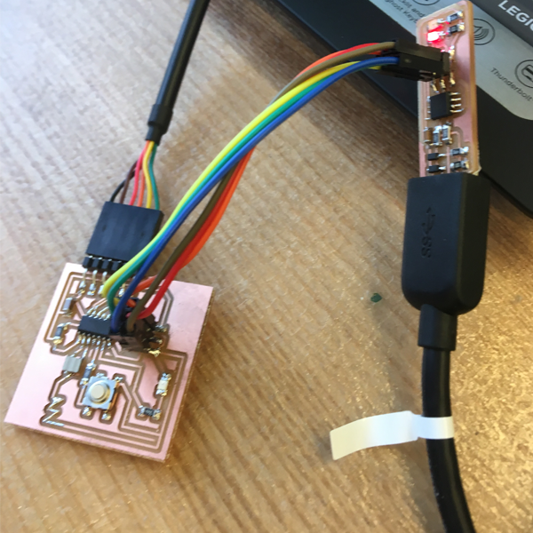
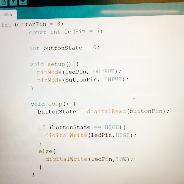
I tried to program with Arduino following Jacky's page, but it didn't work
so I went to meet Anthony that explained me that I didn't do the switch right.
He helped me fix it and add a jumper - and it worked right away!
Thanks to all the TAs that helped me this week.
And here are the design files:
BRD
SCH