The goal for this week was to use some form of input device for an embedded system. Given that I technically never finished electronics design week, and never managed to so much as get my board to connect to a computer during embedded programming week, I'm a little nervous.
Ideally, I want to figure out the input mechanism for my final project this week. This is the system that will allow me to place a cube on a pedestal, and have the pedestal recognize what cube it is. I've been thinking of uniquely identifying each cube based on a pattern of copper vinyl on the bottom. The pedestal will include a grid of open circuits, which will be closed by the cube on squares where it has copper, and left open where it doesn't. However, getting good enough connections all over the cube seems like it might not actually work. A grid of sensors seem like they would work better.
I'm interested in capacitance sensing in particular because it seems like it's able to do more or less anything. It also doesn't require a specialized sensor, which seems like it will be cost-effective for making a grid of sensors. During the group project, Zach, Cameron and I more or less rigged one up out of a piece of copper, a pre-made board, and an oscilliscope. I can then cover the bottom of each cube with a grid of highly capacitive and not-very capacitive materials.
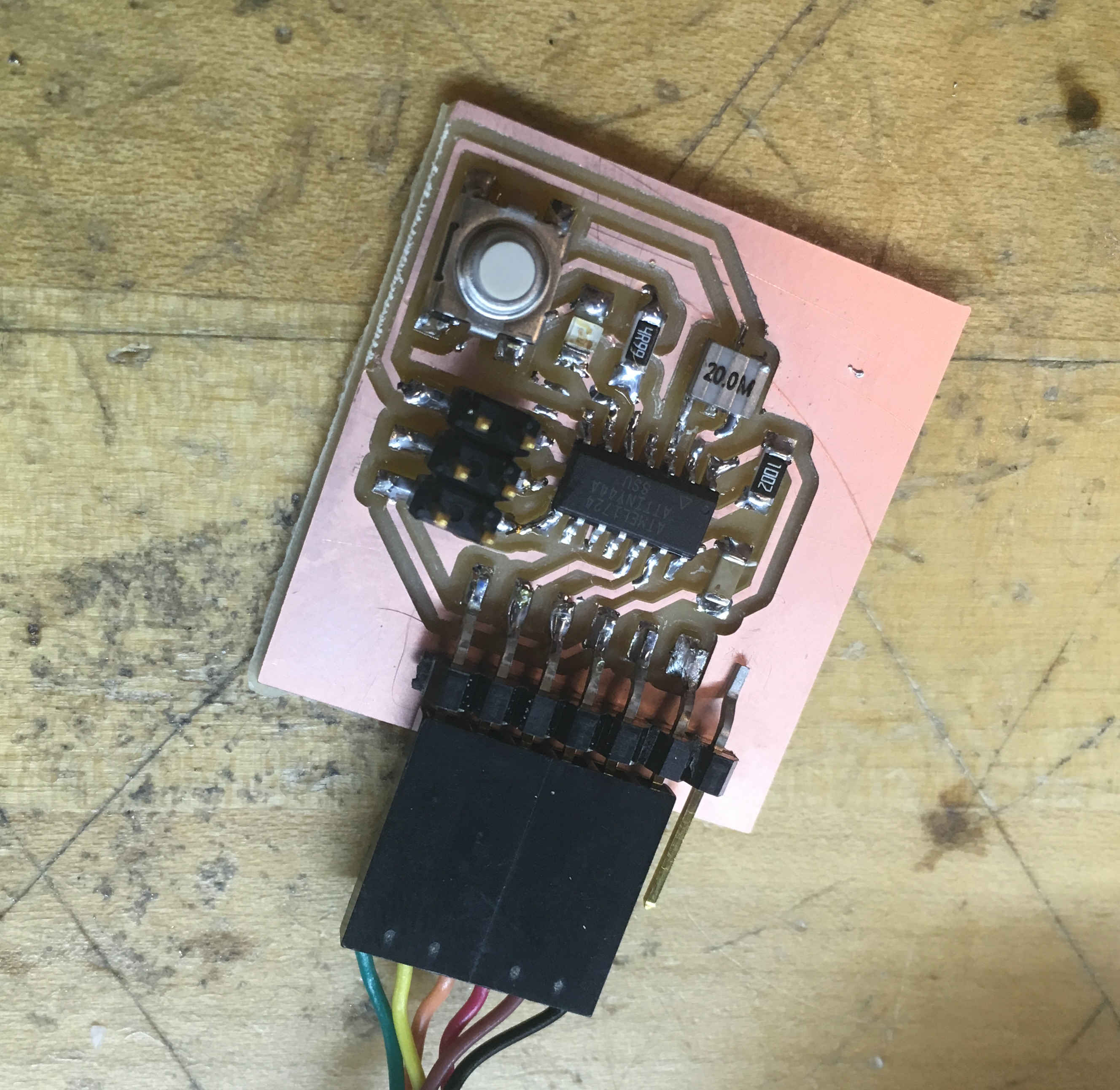
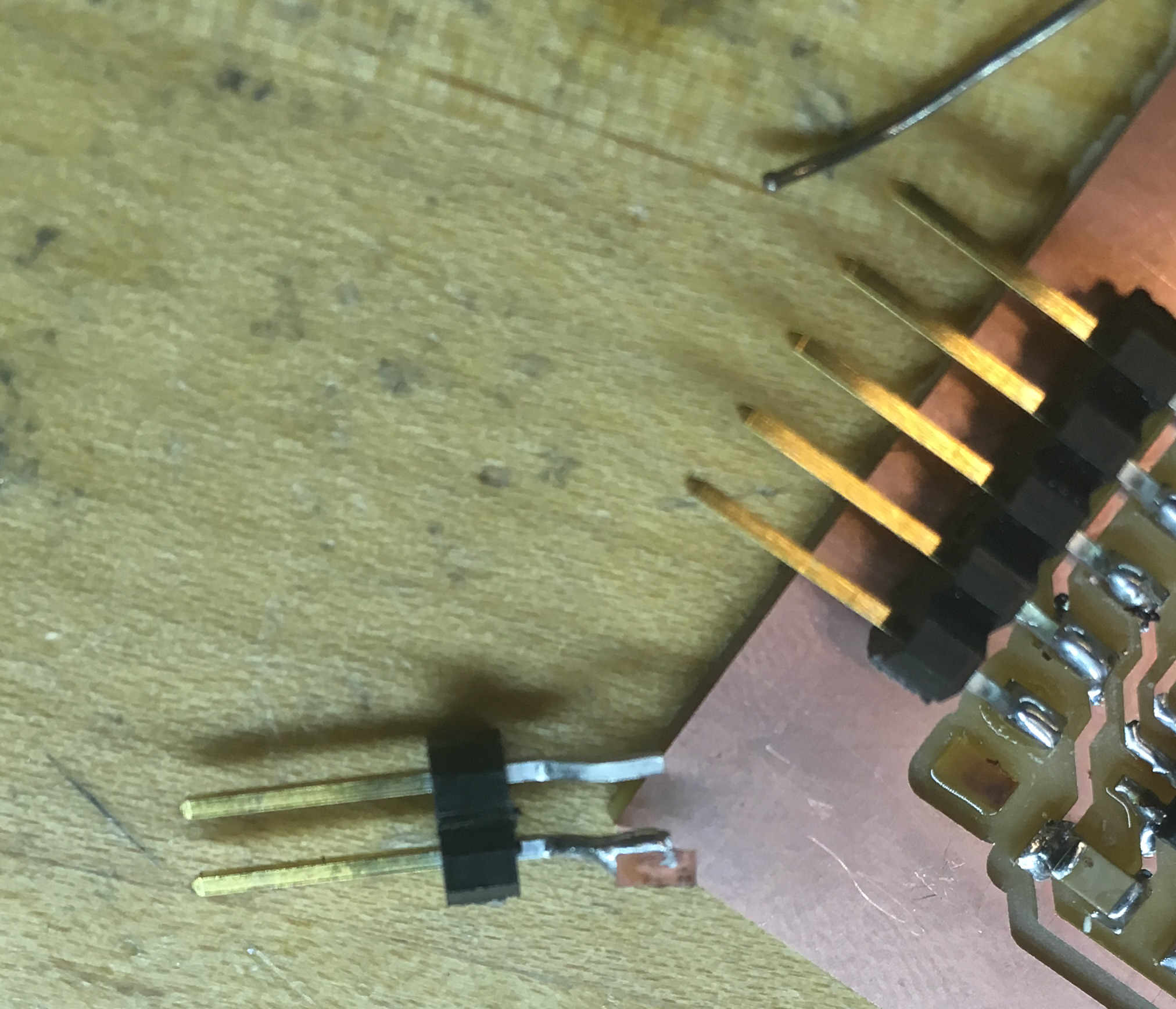
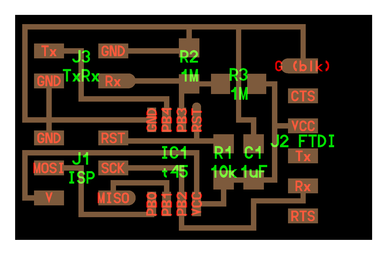
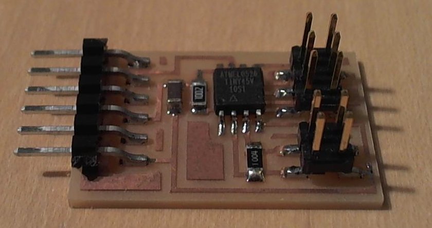
Given that I've still never successfully programmed any board I've made, aside from the programmer itself, I started by finishing the board from electronics design week. I came in Jack's office hours, found the correct copy of the mysterious missing header footprint, and finally printed and soldered my board. While looking for parts, I found that we were out of sections of FTDI header that were 6 or more pins long. I therefore used a 5-pin-long piece, and then used an FTDI cable to hold another sections of pins in place so that I could solder them down.
It didn't go anywhere near as well as I expected.
To be continued, I guess?
First, check out this brief guide to how sensing capacitance actually works.
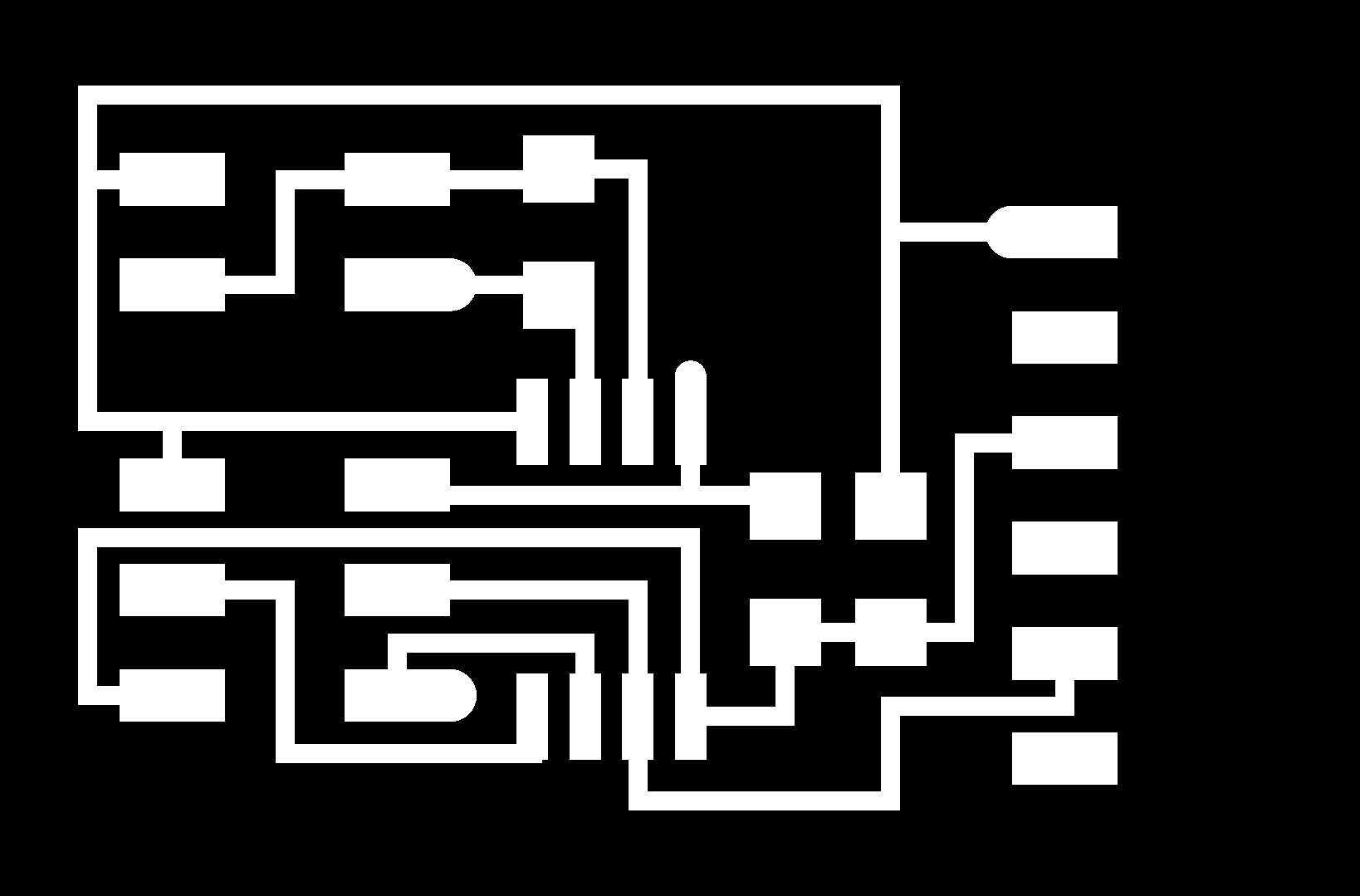
For this week, Neil has already posted most of what you need to make a basic capacitance sensor. HOWEVER. As many people in my year found out the hard way, you are not supposed to just make exactly this board. You should make your own board which looks more or less the same, but which you made yourself, in either KiCAD or Eagle.
After you've milled your board, soldered all of the components on in the right orientation, and have all of the hardware done, how that code fits together and also gets onto that board is a non-trivial problem. Heads up that I solved these problems with a combination of the linux machine in 043 and a windows computer, so if you don't have both of those, you might have to do more research.
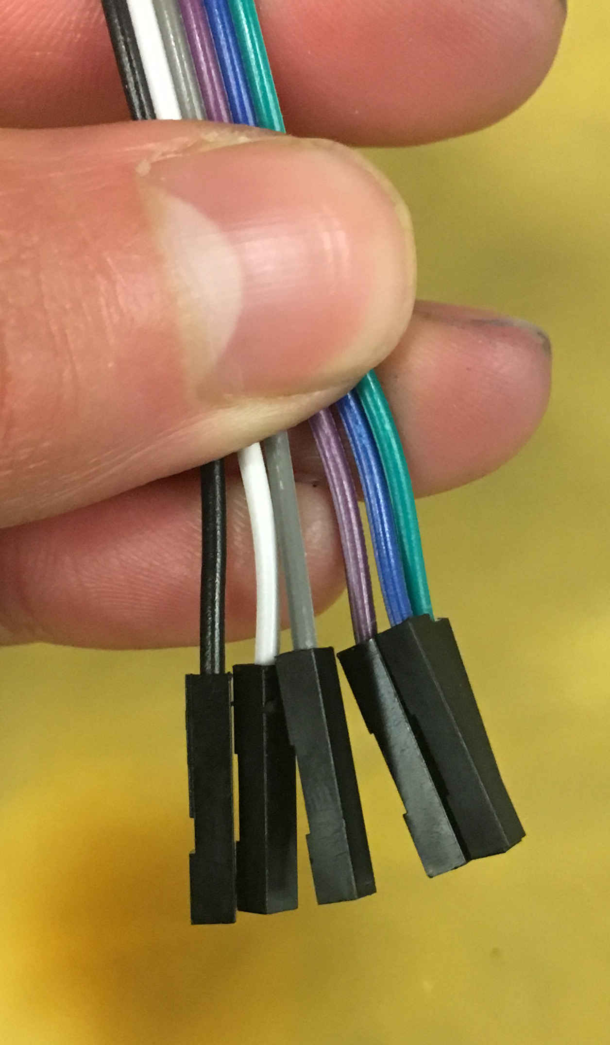
You'll need your programmer from last week, an FTDI cable, and any 6 pins of F/F jumper. If you can't find the nice 6-pin jumper cables that are made for connecting your programmer things, that's okay. Any electrical connection between the pins of the two boards will work.
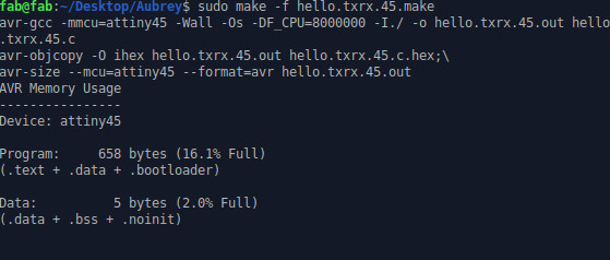
Next, you're going to use the make file to put hex code and the c file on your capacitance sensor board. Make a folder, and put both of these files in there. Open a terminal window, and navigate into that folder. Run this command:
It should give you a terminal output which looks like this:
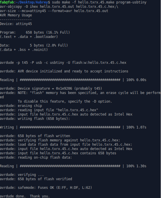
Then, run this command:
It should give you a terminal output which looks like this:
Now, we bring some python onto the scene. Switch to a Windows machine. You don't need the FTDI cable or your programmer anymore. Return it at this point. There are never enough of them, and someone is waiting for it. Python is a very friendly coding language which many people enojoy working with. It's a standard thing to teach to an intro computing class. It also takes a lot of set up in order to use it for the first time. I set mine up using the Sublime text editor, which is free to download and a little like a more basic version of Atom. Open your python file in Sublime. Go to Tools, and Build System within that menu, and set it to Python. Then go to Tools, and click Build. Sublime will now probably prompt you to download Python through the microsoft store. Do it.
If all of your code in Sublime is white, instead of very colorful, Windows has decided that it has no idea what a python file is, and has converted your code to a .txt document. A quick fix for this is to use Sublime to create a file called hello.txrx.45.py, and simply copy-paste the contents of hello.txrx.45.py.txt into it.
An important note: Neil's original python file is for Python2. The version linked about is one that I adapted for Python3. It uses an image rendering tool called TKinter, and between Python2 and Python3, TKinter uncapitalized several things and capitalized several other things in a way that makes code not really compatable with the wrong version of Python anymore. If you're downloading Python from the Microsoft store, it was version3.
Next, open python. Neil's code reqires a library called pyserial in order to talk to the serial that we're getting from your board. To install it, run the command pip install pyserial in your Python terminal.
Finally, we need to know what port your board is at. Computers have tons of serial ports. When you plug in something with a serial connection, it can be hard to figure out which port it will acutally use. To find it, open up Device Manager. There will be a huge list of things, and one of them is called Ports (Com & LTP). It should list one or more items. One of those items is your board.
Finally, run your code. Go back to your python terminal, and run python hello.txrx.45.py COMX where X is whatever the COM number is.
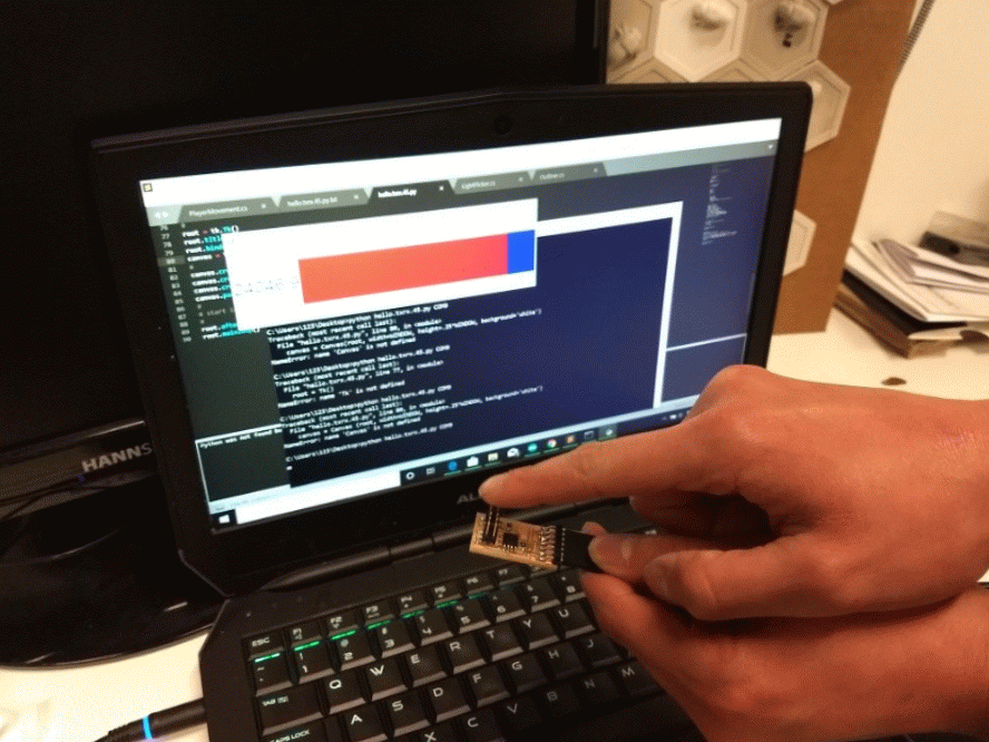
Now that you have a base case working, go wild with it. Add a bigger piece of metal to those four sensor pins. You'll get a much better resolution, and more reliable data if you do.