To get familiar with the laser cutter and how to use it, we tested several of its settings, to see how changing them would effect things like kerf, and its ability to cut through the cardboard we'll be using for the press-fit construction project.
We were too worried about starting a laser cutter fire on our first day to fuss with the focus, but we did set it correctly ourselves.
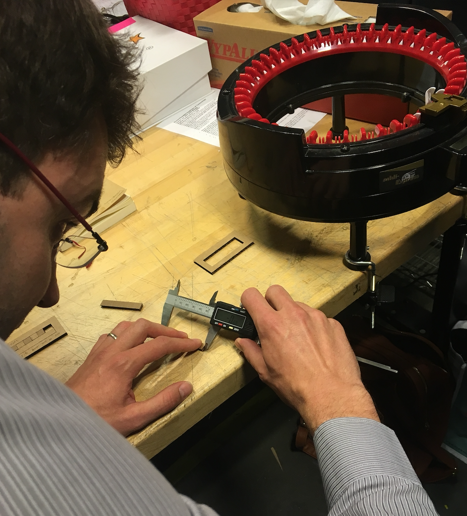
We measured the kerf left behind by the laser cutter for all of our various settings. From this, we learned two things. The first is that, for every setting we tried, the kerf was reliably within 0.1-0.3mm. The second is that digital callipers on a flexible material like cardboard have a margin of error greater than 0.1mm when weilded by people with very little experience with them.
We created an array of squares, to compare a variety of different power levels.
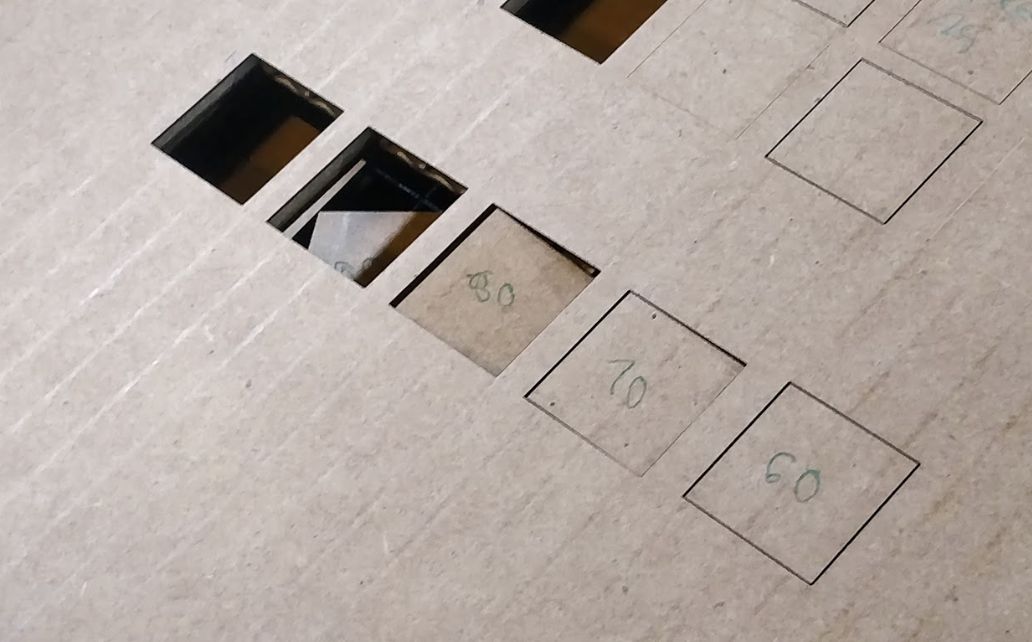
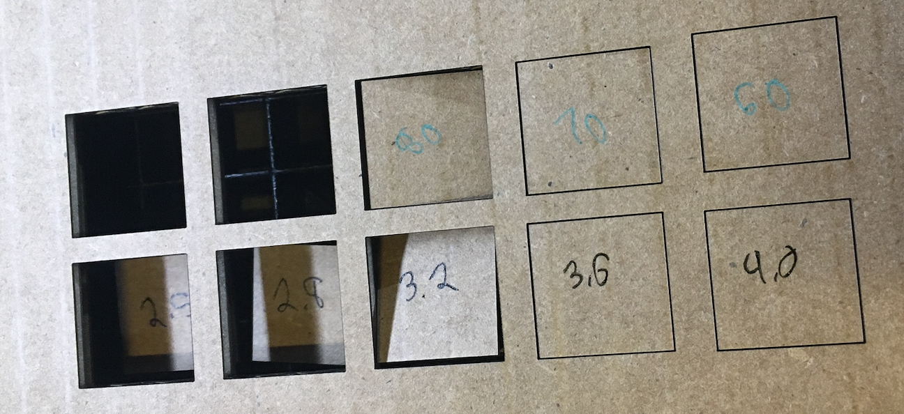
5 squares printed with varying power levels. From left to right: 100%, 90%, 80%, 70%, 60%. All printed at a speed of 2.5 and 200 ppi.
We found that 90% power will cut through our cardboard, and 80% would cut through, with some encouragement.
We then got interested in scoring cardboard. We tested out much larger reductions in power level.
5 squares printed with varying power levels. From left to right: 50%, 100%, 25%, 12%, 6%. All printed at a speed of 2.5 and 200 ppi.
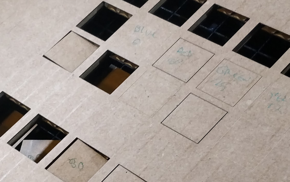
After fussing with the power level, we realized that it probably never makes sense to turn the power of the laser down-- you should probably keep it at 100%, but run it faster at the same ppi. We therefore switched to varying the power level.
Top row: 5 squares printed at 2.5 speed, 200 ppi, and power levels reduced by 10% for each square from 100% to 60%. Bottom row: 5 squares printed at 100% power, 200 ppi, and a speed increased by 10% for each square, from 2.5 to 4.0.
We found that reducing the power by 10%, and increasing the speed by 10% have roughly the same effect.
We also varied the ppi, and found that, at a speed of 2.5 and a power level of 100%, anything between 100 and 250 will cut through our cardboard without setting in on fire.
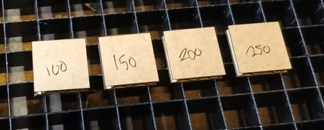
4 squares, printed at a speed of 2.5 and a power level of 100%, with ppis of 250, 200, 150, and 100. Not pictured: on printed at 50ppi which didn't cut all the way through.
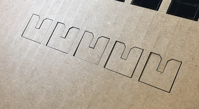
We had a lot of fun figuring out exactly how wide our cardboard needed to be cut to make well-fit joints. We realized that we were having a hard time measuring kerf, so instead of figuring out how much material was lost to it, and accounting for it, we made measurements which include kerf. We printed a series of notches set to different widths in a CAD file, and tested which created the best fit with our cardboard.
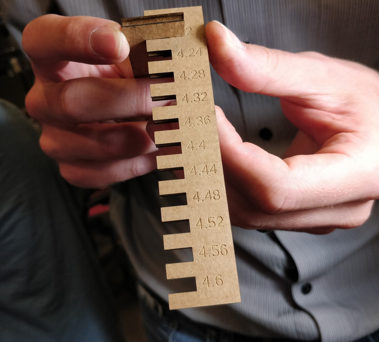
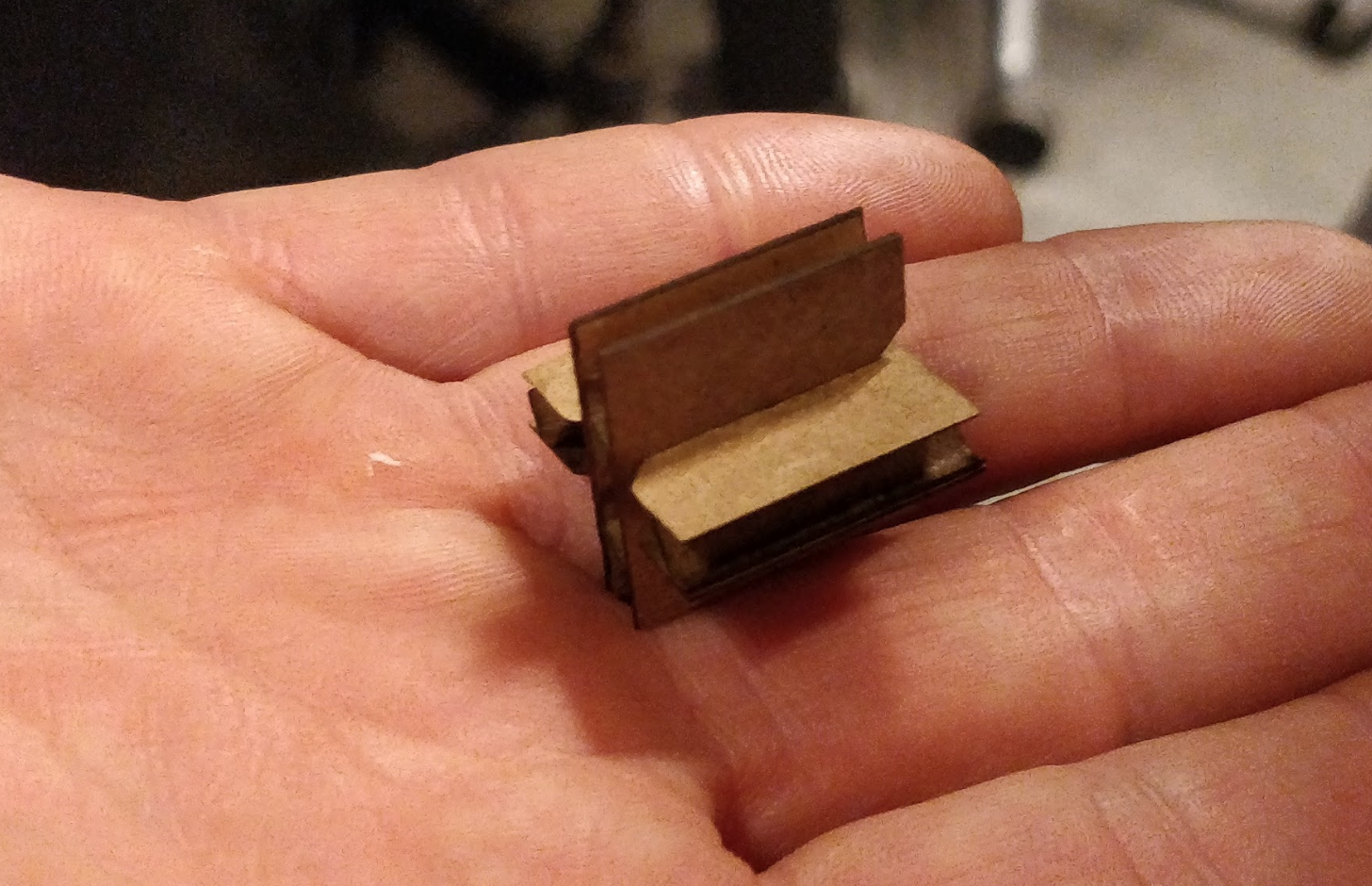
We found that notches set to 3.9cm in a CAD file create an optimal fit with our 4.4cm cardboard. This suggests that the total kerf from both sides of the notch, plus the squish of the cardboard, add up to about 5mm. While the fit is tight enough to be a little hard to assemble, we found that, with a slight chamfer, we had something which could be easily assembled, yet secure.