To get familiar with the mill, we printed a few test pieces on a few different settings.
After being trained on the SRM-20 in 043, a large crowd of people were going to characterize the machine we had been just been trained on, so a few of us used the one in CBA, assuming that they'd be more or less the same.
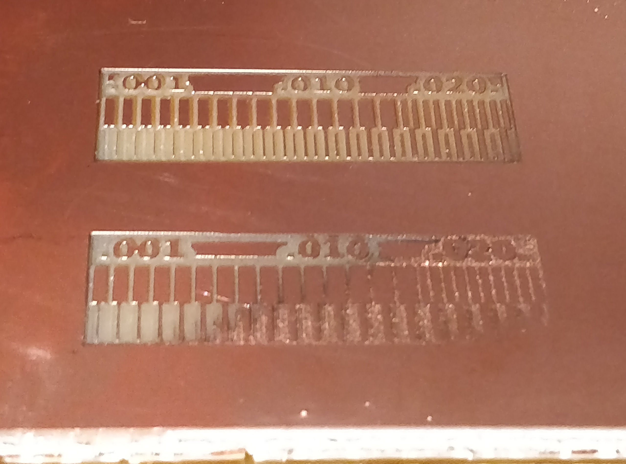
We first milled a default stock image with the 1/64" endmill, an offset of 2, a cut depth and max depth of 0.004. We knew that it wouldn't go all the way through, but we wanted to see what fainter etching looked like. Then, we milled a second at the same settings, but with a max depth of 0.008.
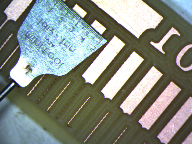
The milling machine does have a small kerf with the 1/36" endmill. We cut out our test token with the 1/36" endmill, and found that it's width (11.84 mm) was almost exactly image height in mods (12.80 mm) minus twice the line width (50 px at 2500 dpi, so 0.02", or 0.508mm total). The missing 0.452mm is the combination of whatever kerf the machine had (X2, for both sides), plus general human error using digital callipers.
After printing our test token, we decided to take a closer look at the edges of our traces looked like under a microscope.