This week, to learn how to do PCB fabrication, we fabricated a programmer. I'm still not entirely sure what that it, or how it works yet, but I do know how to make one. I mostly got through this week by following Brian's documentation as carefully as I possibly could. I learned to solder on the exactly one arduino project I've done in my entire life. As someone who has basically no background in EE-type things, this week was spooky.
I had a bit of a headstart, because I got to keep the board we milled in the training. I actually kept it in my shirt pocket all weekend to show it off whenever I talked about this class.
The most suprising thing about this week was how small surface-mount components are. I found that, if one of my components was flipped over, the easiest way to get it right-side-up again was to pick it up with tweezers and drop it until it happened to fall the right way.
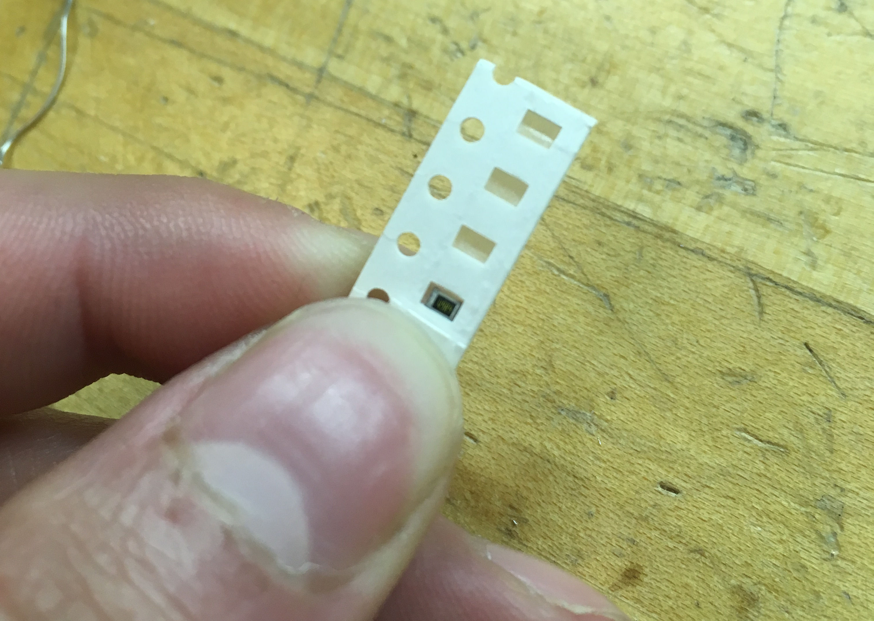
That tiny black speck near the end of my thumb? That's the resistor I'm going to try to solder.
I struggled a lot with getting components to stay at the right place on the board while I soldered them down. I did a lot of accidentally pushing the component away from where I needed it with the solder when I tried to touch the solder to the joint. The chip was especially hard to line up, but turned out to be large enough to just clamp onto the board while I soldered it down.
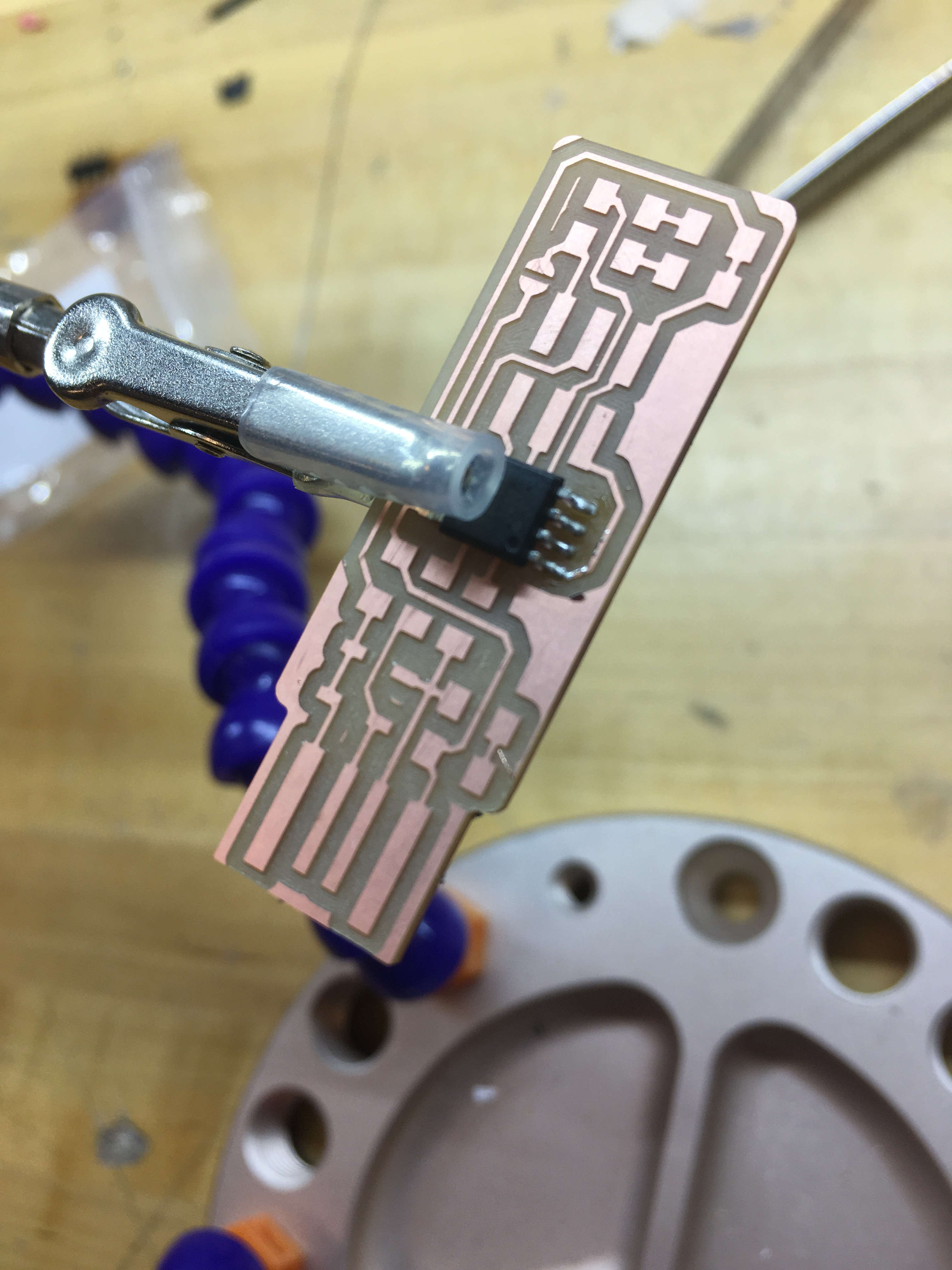
hold. still.
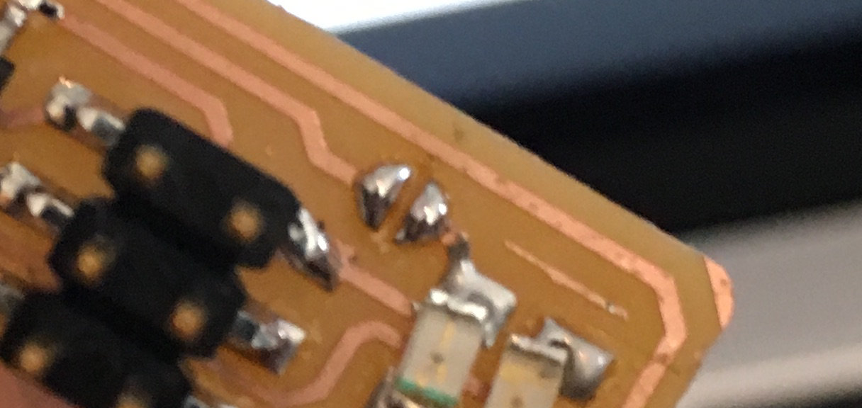
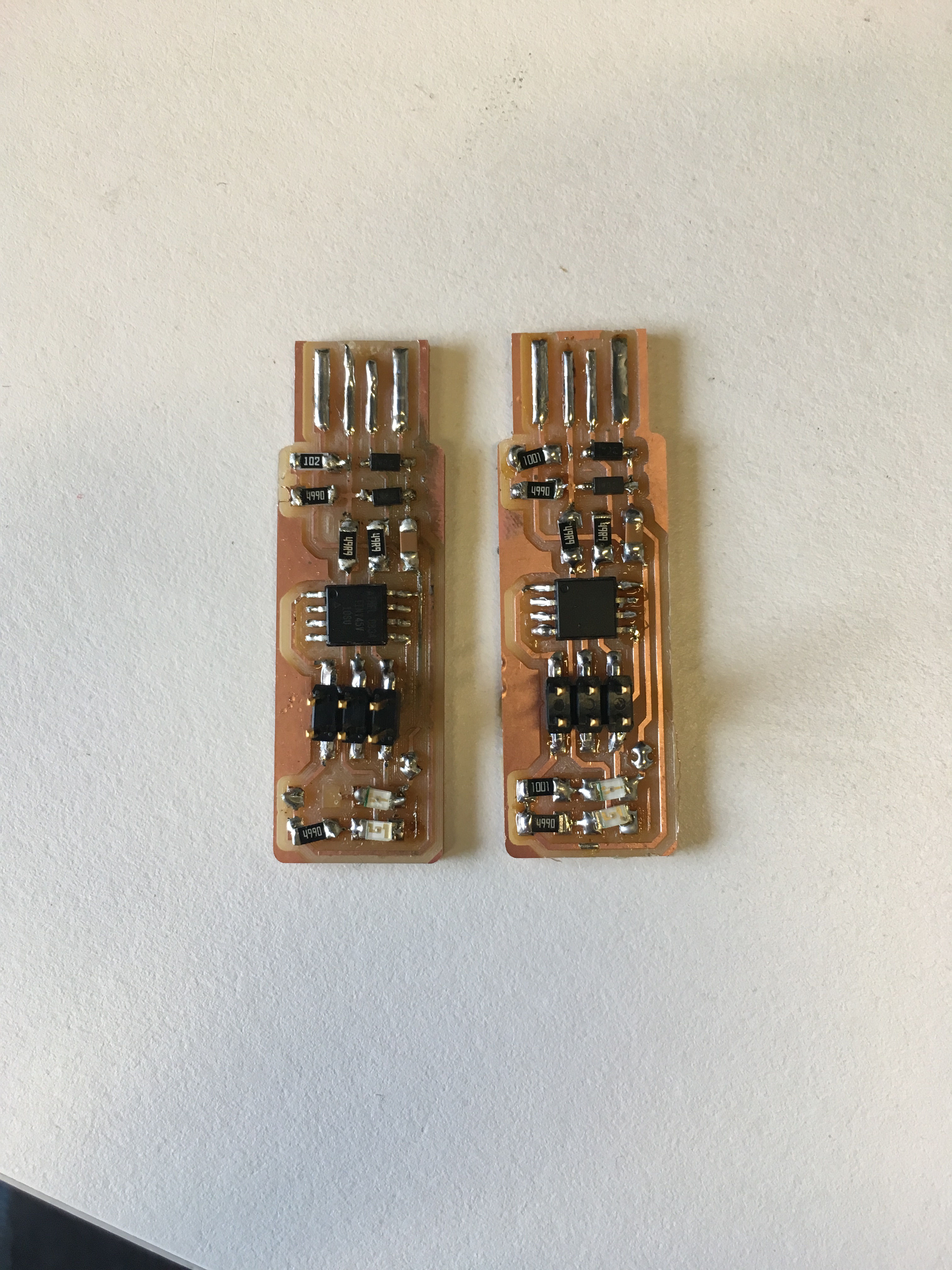
With my board fully soldered, it was time to test it out. The second I plugged it into my laptop, the connection between the board and the port poured out smoke. I pulled it out, and compared my board to the board in Brian's documentation a little more closely. The numbers didn't quite match up. The 1k[insert ohm sign] resistor on my board said 102, and the one on Brian's board said 1001. I thought that the resistors in the drawer might have been mixed up, although someone else in shop later tried to explain to me that 1001 and 102 in resistors means the same thing, because the last digit is the number of 0s. Regardless, I decided to make my board look more like the picture, because I couldn't see any other obvious problems with it.
In the process of desoldering my mystery resistors, I managed to rip up one of the copper traces, and I was pretty sure the smoke from earlier wasn't great for my other components, so it was time to mill a new board.
R.I.P., little buddy
Milling the new board took a lot longer than expected, largely due to the fact that I didn't spend anywere near as much time characterizing the mill as I had the laser cutter. The first time I tried to cut the traces, I used a cut depth of 0.002 in, and a max depth of 0.008, with an offset of four. This didn't cut the entire board.
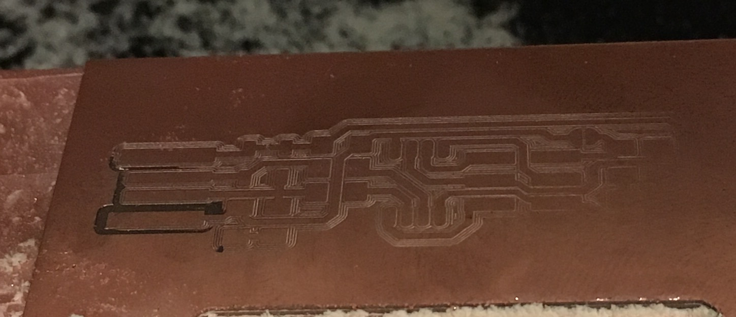
The ghostly outline of electronics past
Next, I tried to double both the cut depth and the max depth. Unfortunately, I sent the file to the machine without it actually updating in mods, so it took ten minutes to do exactly the same too-shallow cut again.
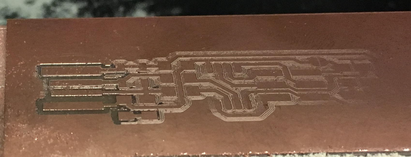
The ghostly outline of electronics past, but closer this time
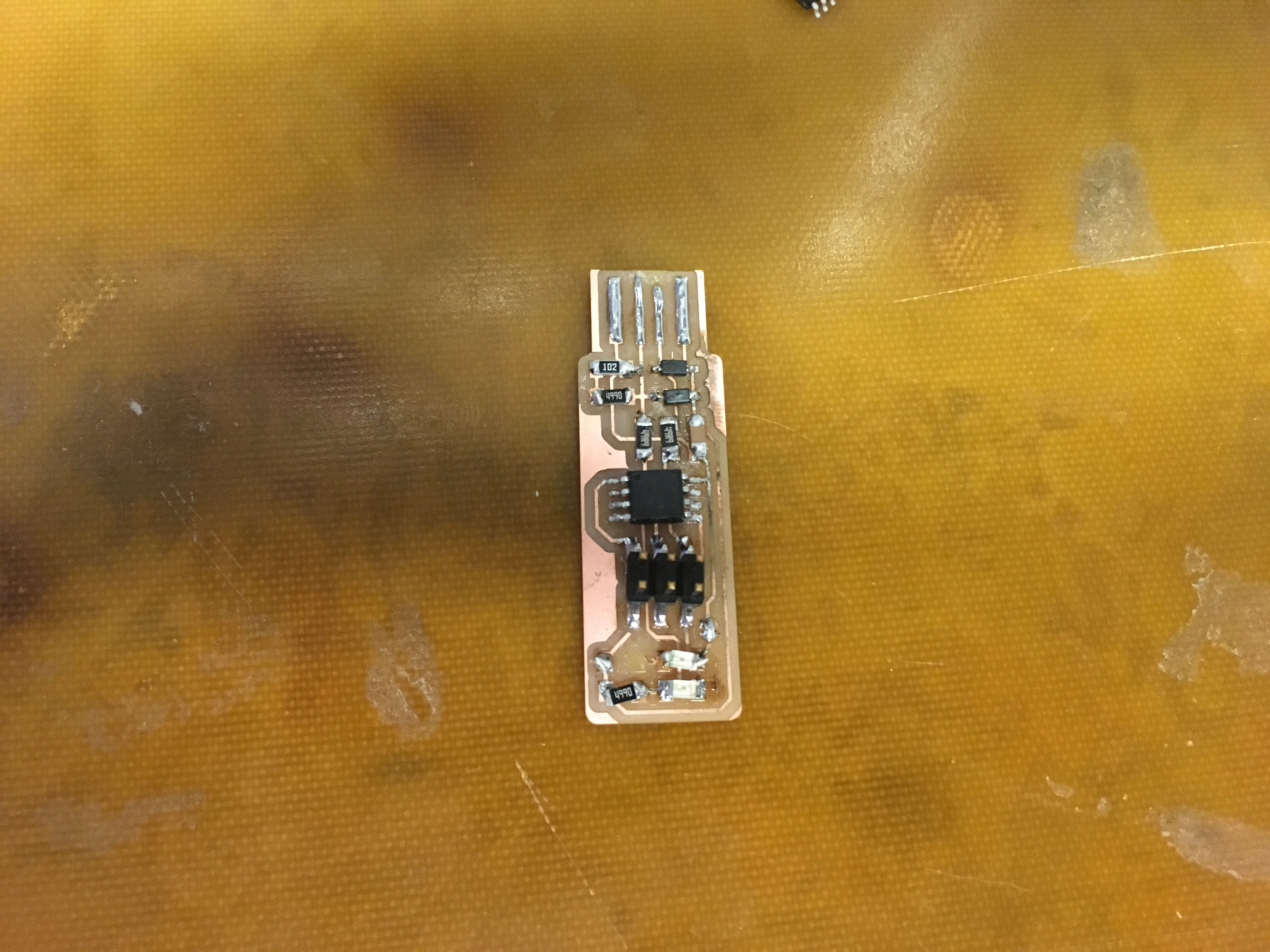
Finally, after my third attempt at milling the board, I had something I could work with.
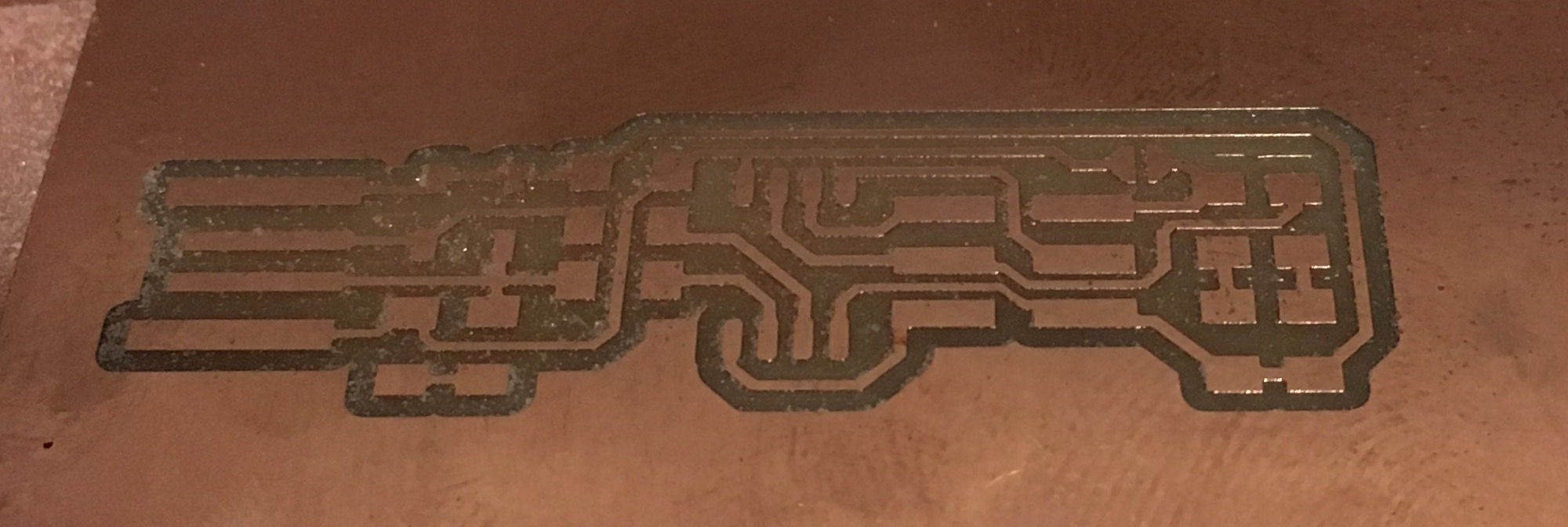
Electronics!
The new board looked a lot better than the old board. There's something to be said for scrapping your work and starting over, once you actually understand what you're doing.
Then came programming it. Several of us taught eachother how to do this while gathered in 043. Just painting four prongs of solder on something so that it fits in a USB port does not make it a USB device. Our board is just a pile of electronics until we tell it that it's a USB device. In order to communicate wtih our new programmer, we need to first plug a working programmer into it, and run a few lines of terminal magic. Because my tiny macbook has only one port, this was a bit of a production.
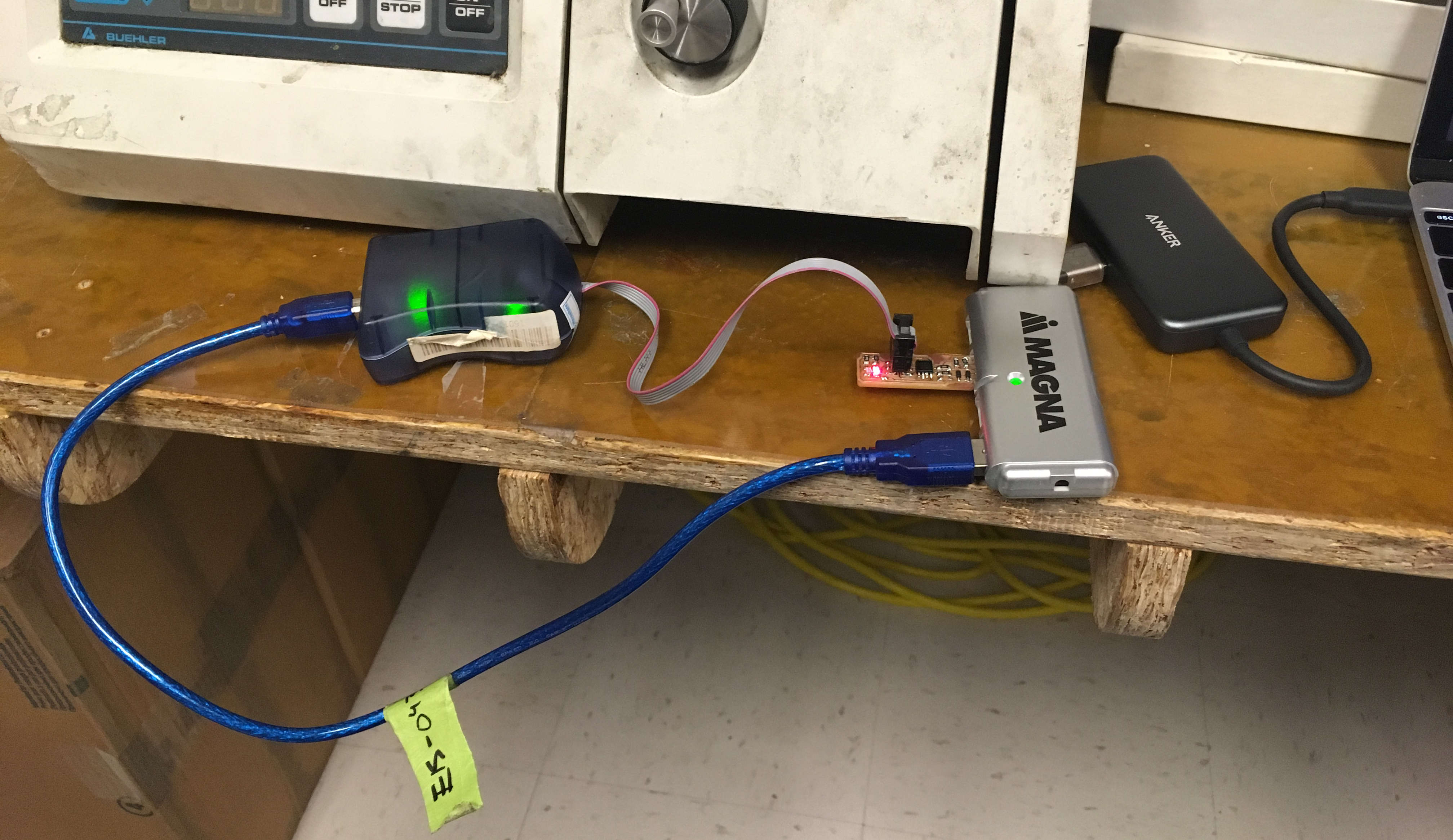
Here we see both the programmer and the board to be programmed plugged into a USB2.0 hub, plugged into a USB3.0 hub, plugged into the only port on my tiny, tiny computer.
I eventually gave up on this and just used the linux machine in 043. After this machine recognized a "Multiple Vendors USBtiny" device, I ran the final terminal command on it, and cut the solder bridge to make it be a programmer.