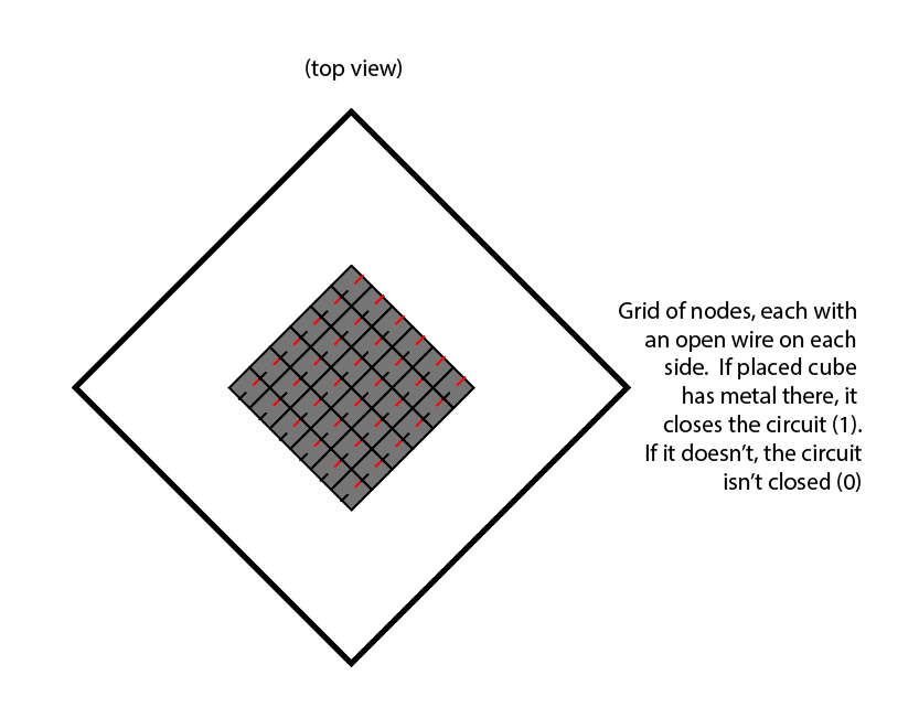
I've been nervous about making my "sensor" (henceforth refered to as a "cube reader, because it feels dumb to call something that more or less senses the presence of comductive metal touching both nodes a sensor") all semester. Jake suggested using rectangular pogo pins to make sure I get a good electrical connection between my box and sensor. He also suggested that I make the main plane of the sensor VCC, have the pads of the boxes connect VCC and each GPIO pin, and then just read if the pin is high, for each pin.
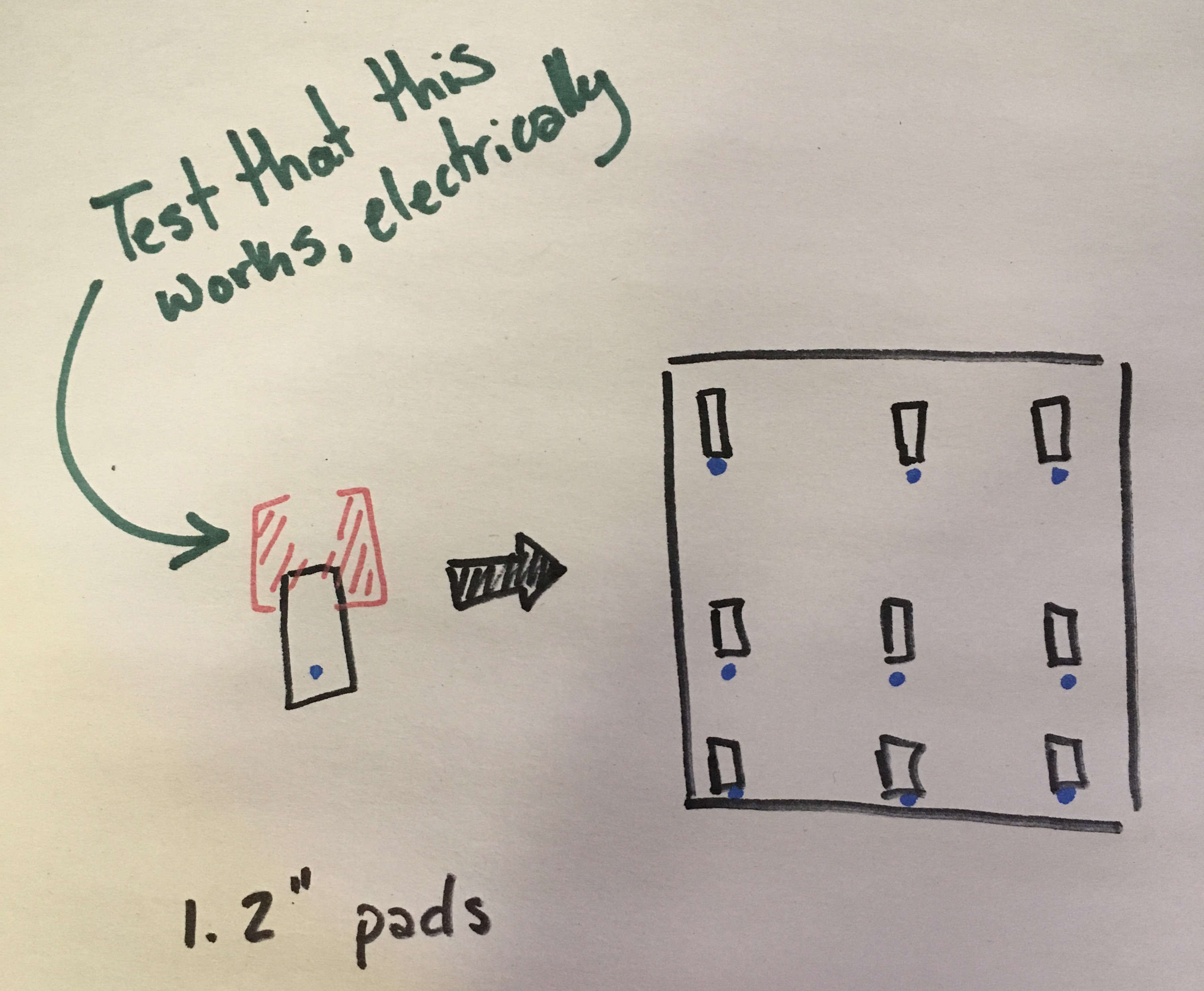
I ran a quick test using an LED and....
It works!
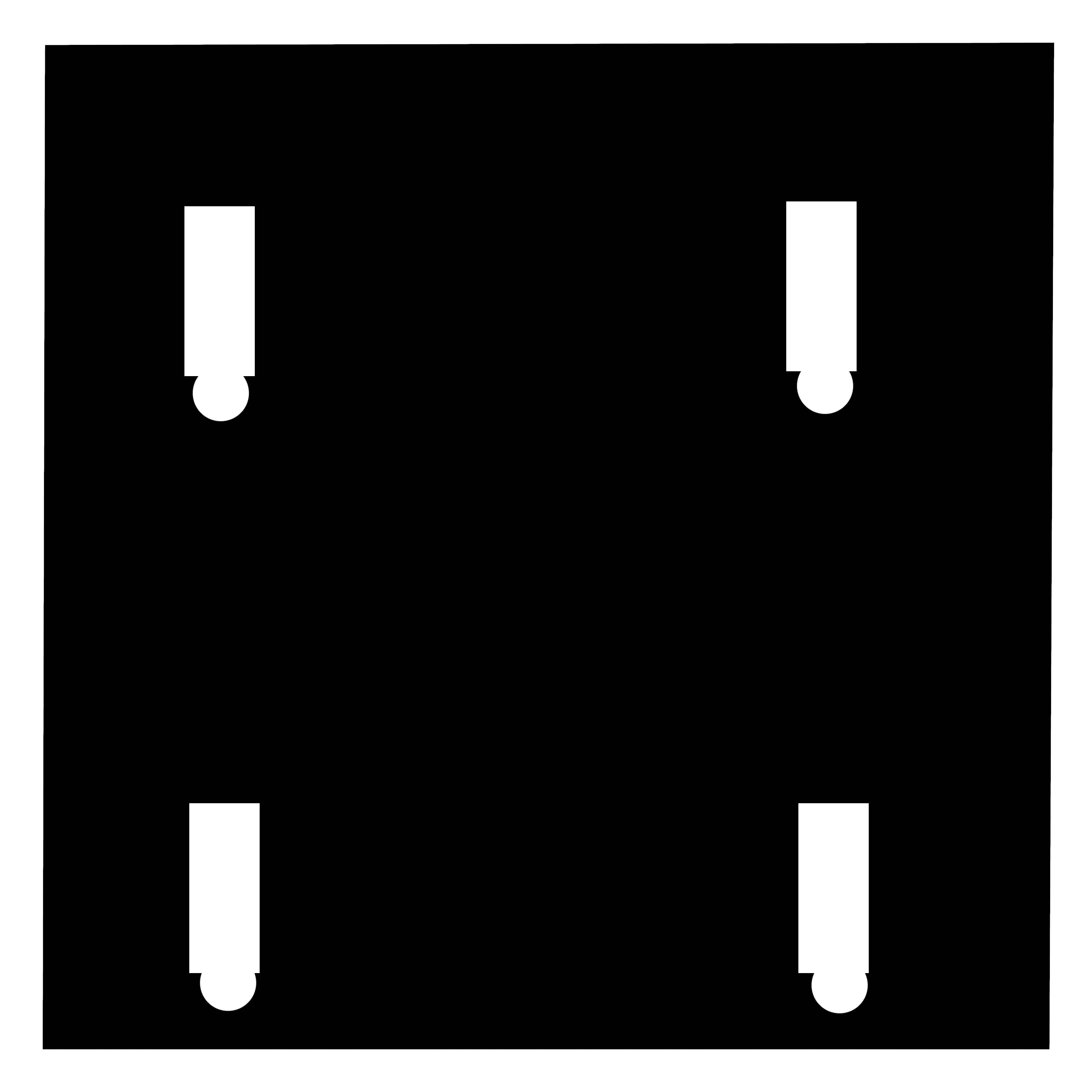
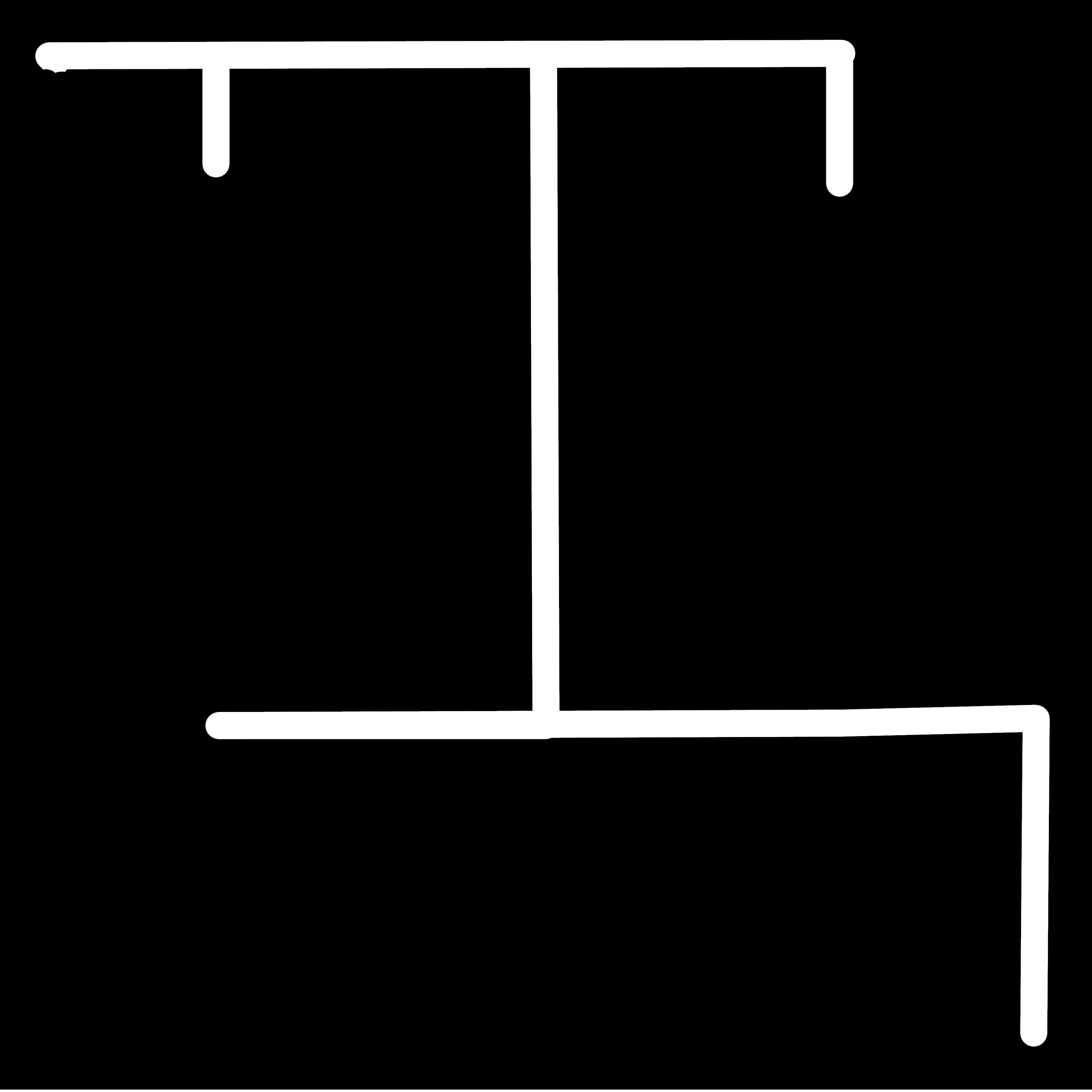
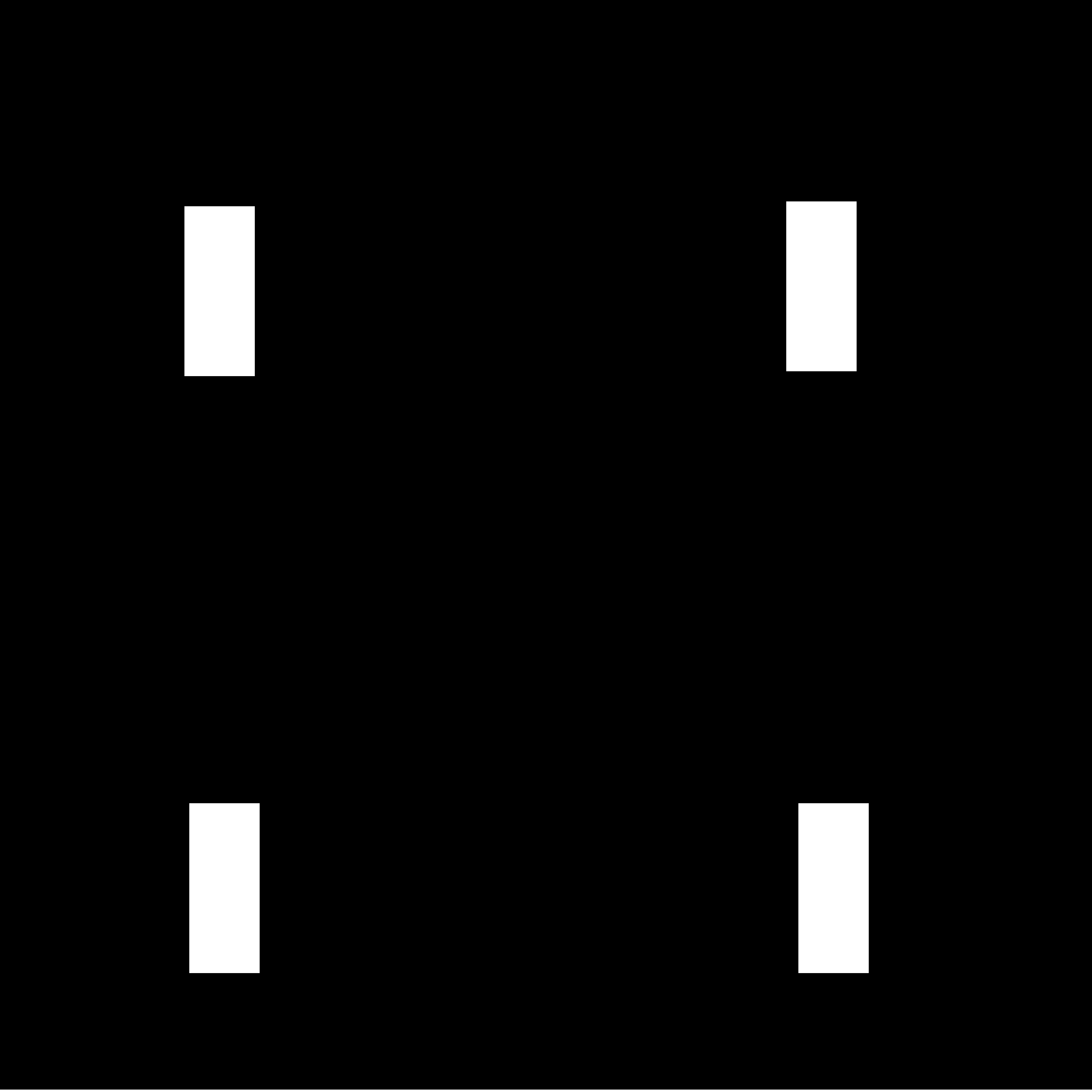
Then, it was time to actually design the board. Because it's so simple, it made more sense to just draw it in GIMP than to make footprints for this. It isn't perfect, and that's fine. It should work, probably.
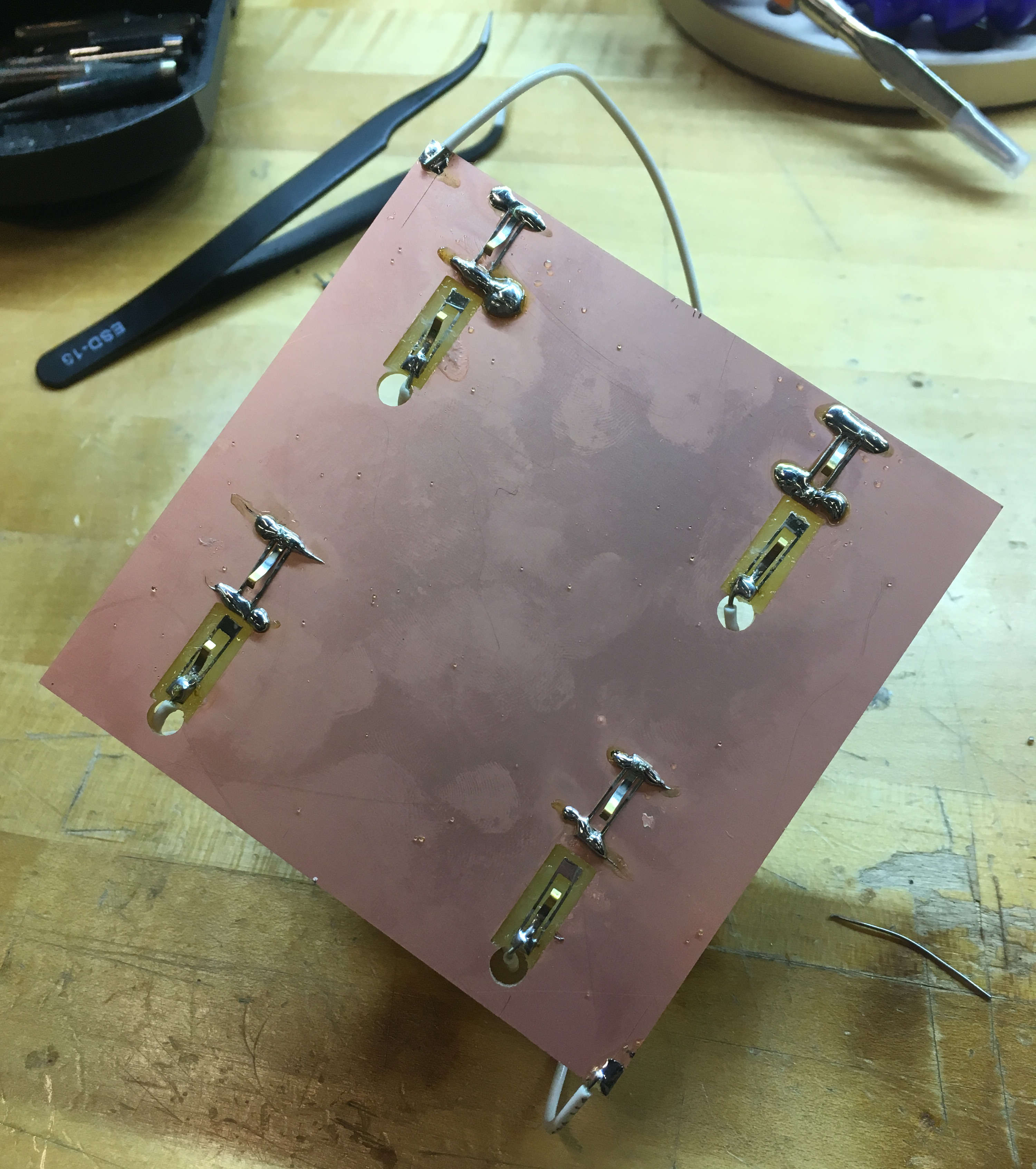
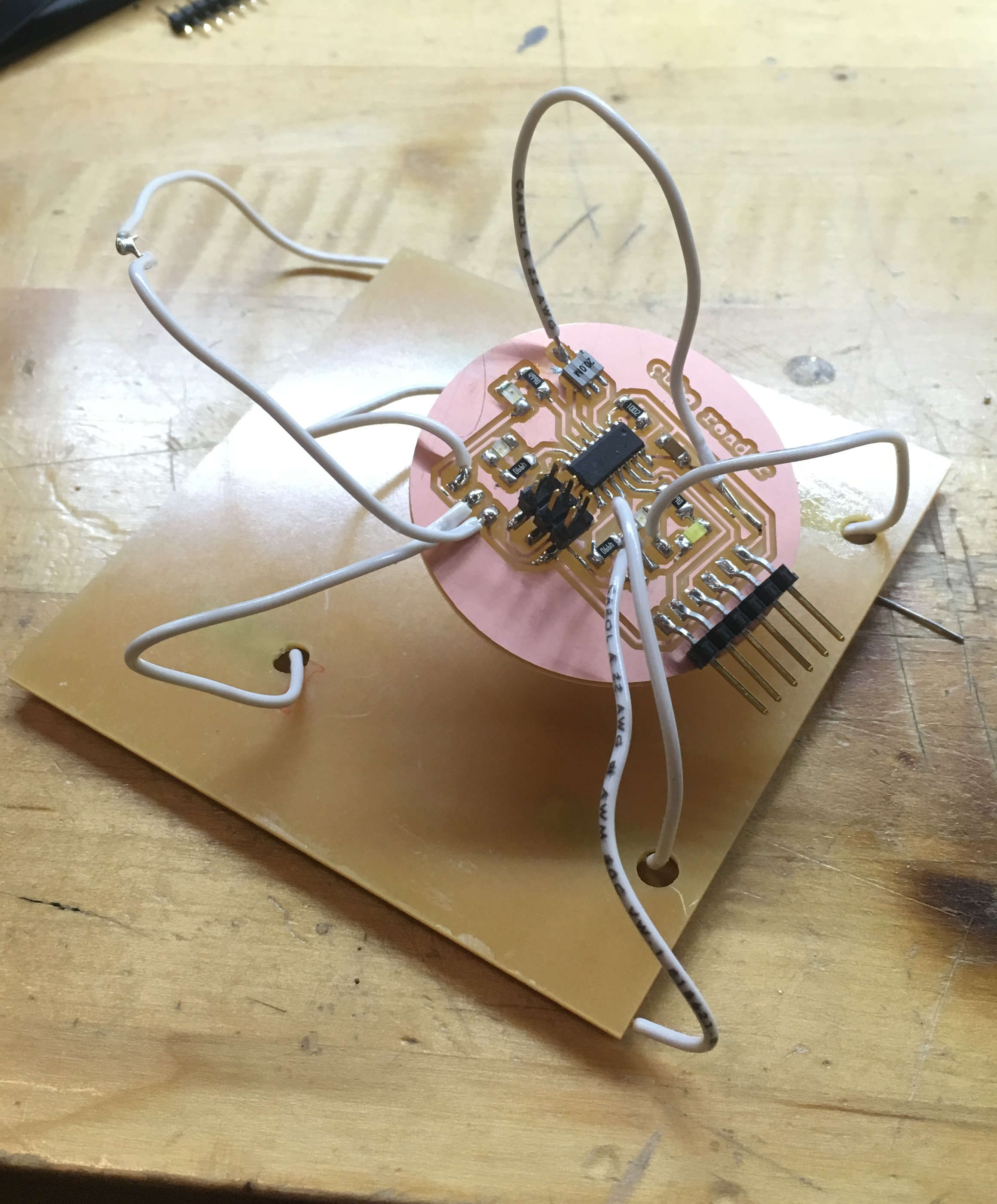
My ugly spider son side a. Four of the pogo pins are held to the board with super glue.
My ugly spider son side b.
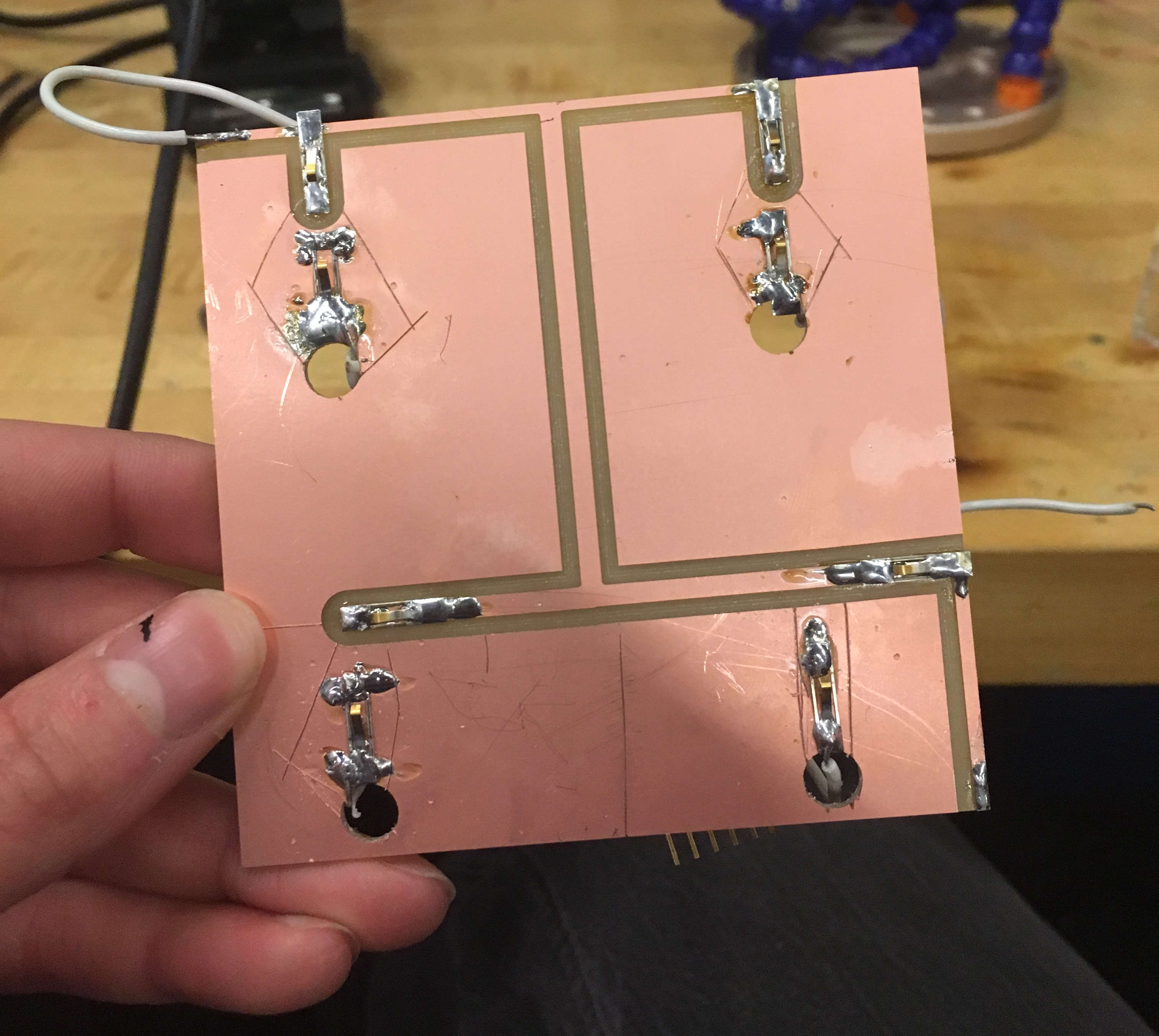
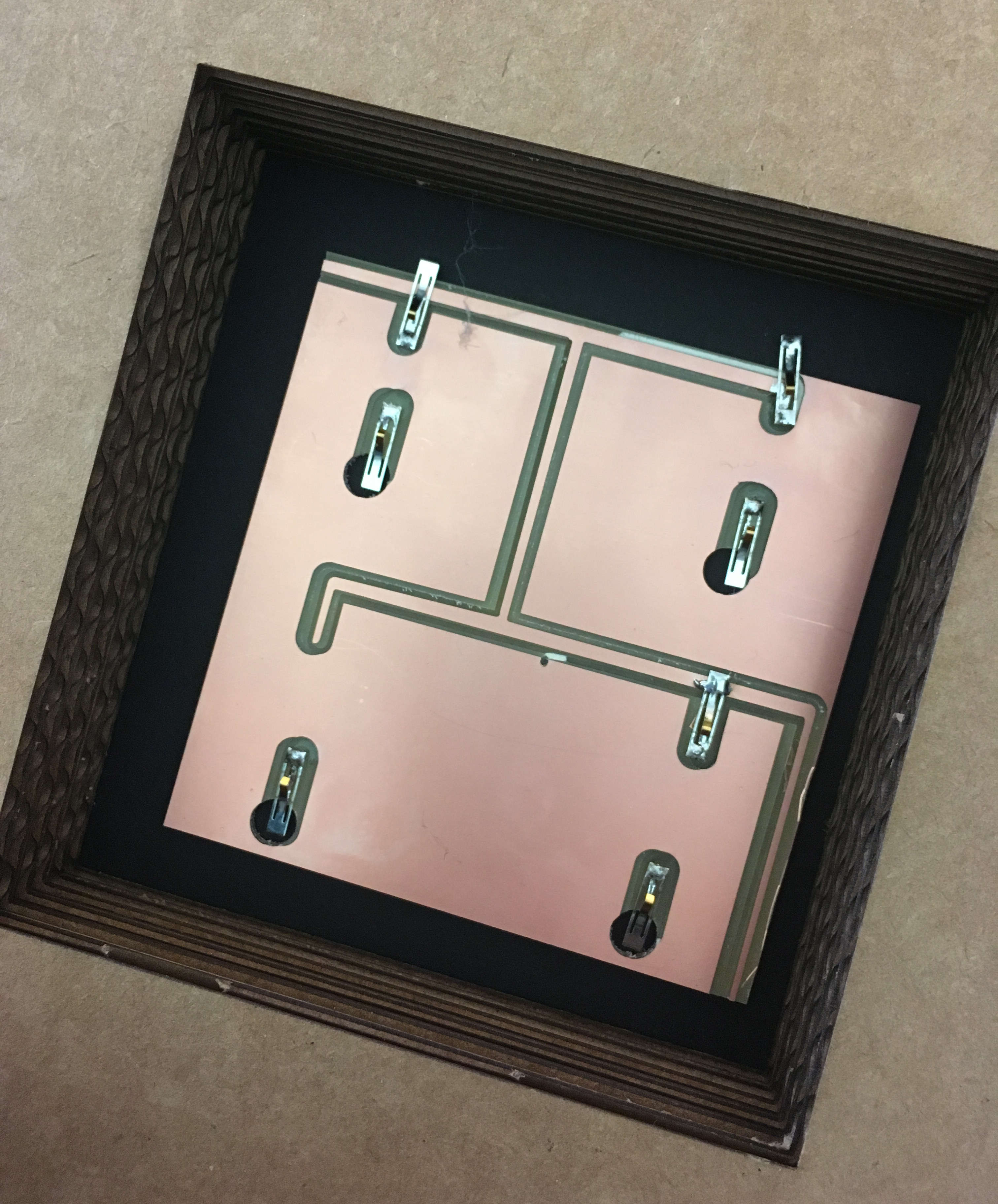
While this did not work, I think it taught me a lot about how electricity works. From each corner of the sensor to the other, we get 5 volts. But between any two points on this board, such as the points that we are trying to connect, we get an almost imperceptably small voltage. This is because, like water in a stream, when all of the electrons being forced through narrow traces run into this huge delta of flat copper, they spread out and slow down. I made a pond.
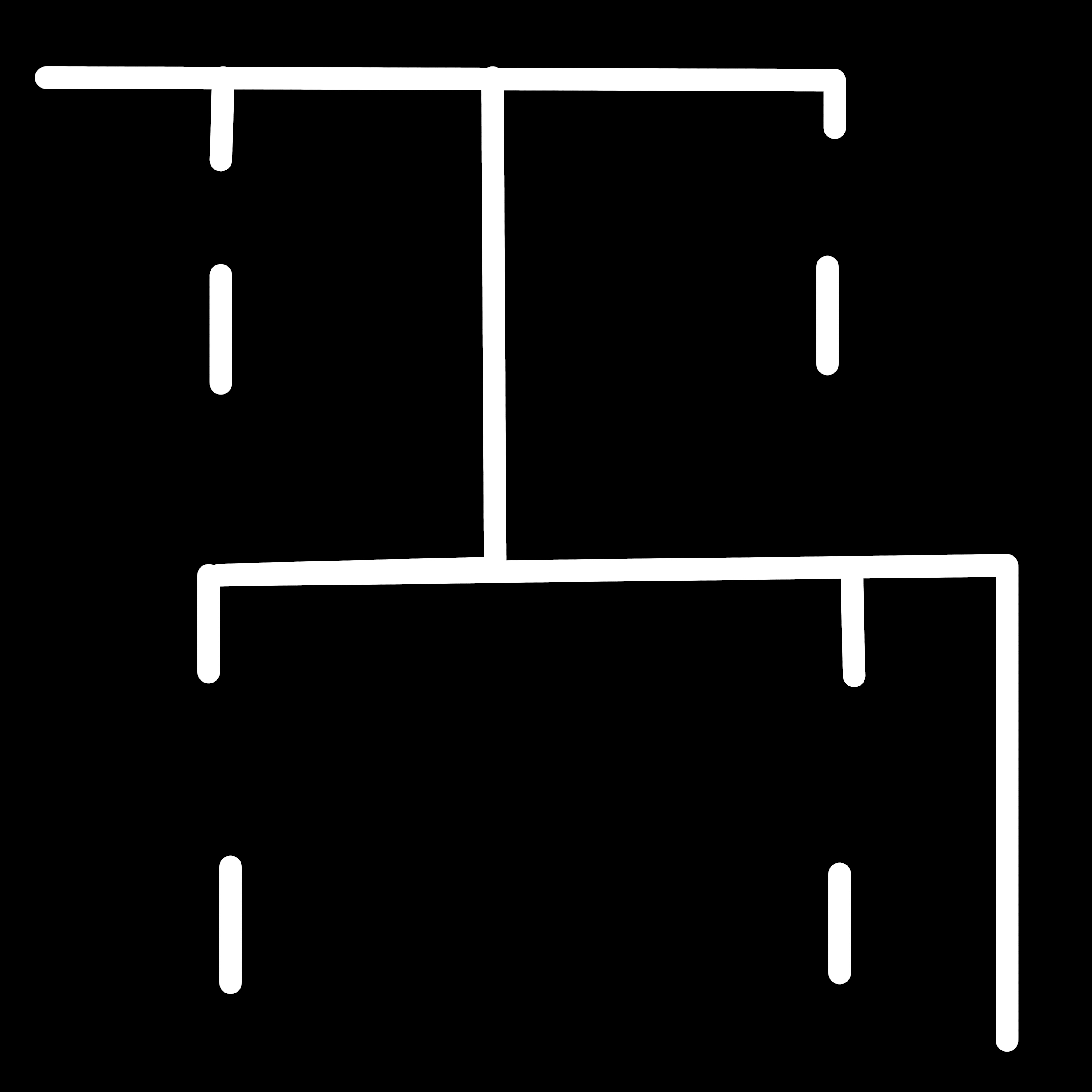
So I made a new sensor, with actual traces.
This one had the same issue, but to a slightly lesser extent. The pogo pins connected to the GPIO pins were also connected to the ground plane. This connected them to eachother, and made the voltage diffuse. I tested that isolating these pins from the surrounding copper would fix the problem by separating them with an exacto knife.
This made LEDs light up in the right pattern when VCC was applied to the right places. One more iteration cleaned it up?
final version of the sensor housed in the pedestal