Week 10: Output Devices
For this week's output assignment, I wanted to design, stuff, program and test a board that includes both a color LED and accelerometer that I could use as a starting point for my final project — programmable smart juggling balls.
Designing the Board
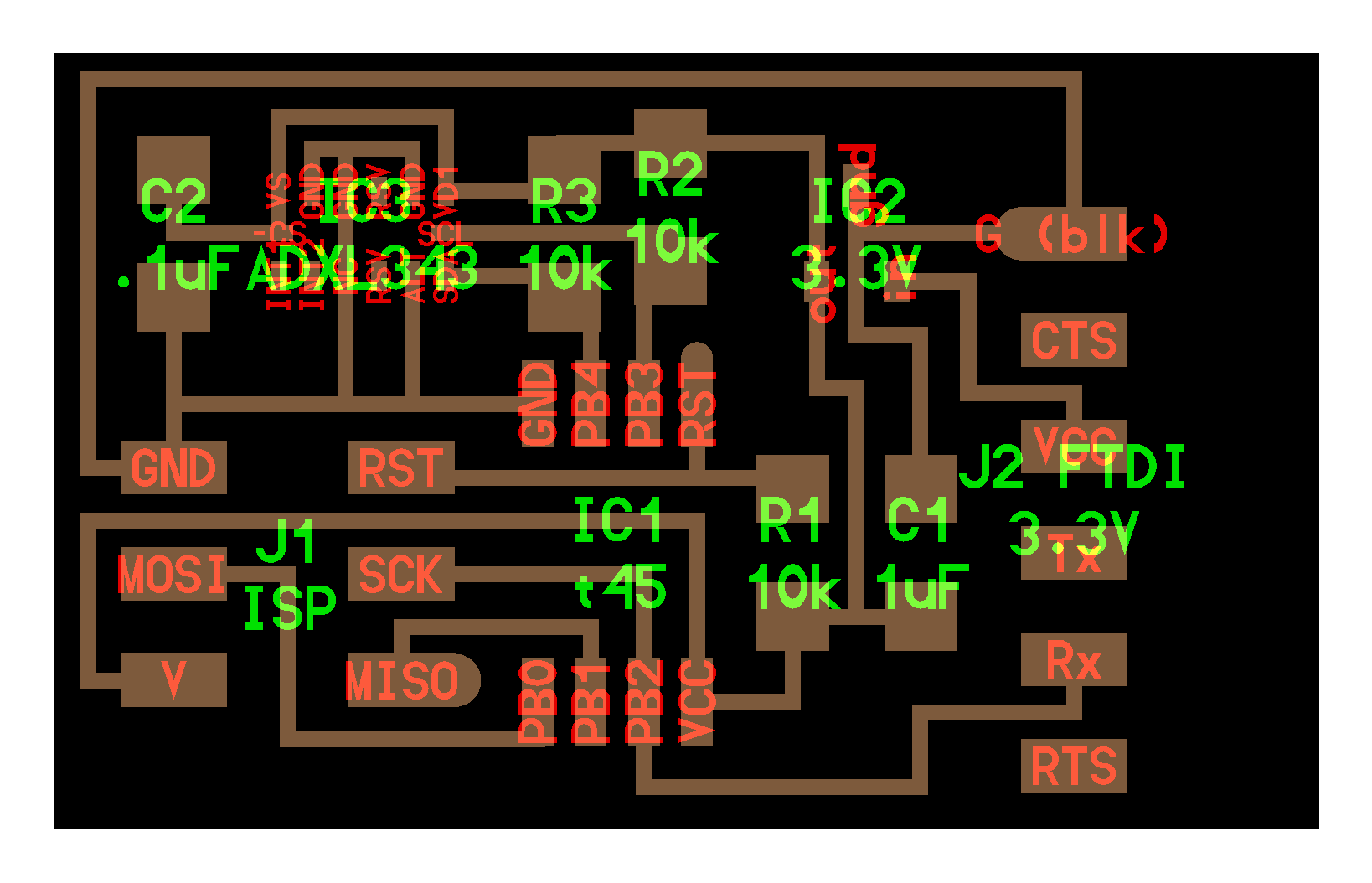
I started out by designing an accelerometer board, closely following Neil's ADXL reference traces.
I decided to try out EAGLE instead of KiCAD this week (partially because both my lab members and Jiri have more experience with it), and was glad I made the switch. I found the command omni-bar, keyboard shortcuts and UI generally easier to work with.
A few interesting things I learned:
- V (power) is typically laid out from the top, and ground at the bottom. There are also built-in library assets to add nice-looking graphical V / Ground icons to your board layout.
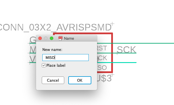
- You can name wires in order to connect them across a long distance. This allows your net to look like separate logical components and their dependencies, rather than a rat's nest of connections. Reminds me of extracting methods / introducing classes in programming!
I exported the board to PNGs:
python eagle_png.py Accelerometer-After-Jiri.brdThis generated .top.png and .cutout.png files. Jiri warned me those files would have 3000 DPI - after importing in to mods I would need to set the DPI to 3000 in order to avoid having a double-sized board. I experimented with explicitly using eagle_png.py's DPI setting, but it did not help. It did seem to pass in the correct parameter to EAGLE, but EAGLE would generate the wrong DPI.
The library's default pads for the ADXL and power IC2 converter were too large for our design rules and the 1/64:

Here's a comparison of the sizes of the pads in Neil's version (selected) and mine. Oddly when I copied one into the other the centers didn't seem to line up.
(Ultimately after milling, the pads seem to line up, but the independent pads came off:)

Milling the Board
For the first time of any of the weeks, milling Z-axis zeroing went smoothly (no need for re-runs)! Some things I made sure to do that may have made the difference:
- I checked the mill was still good / had enough sharp edge left on it
- I replaced the sacrificial layer as it had begun to bow upward and would change Z-height when I pressed down.
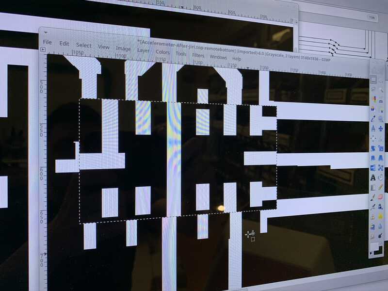
On the traces, during my board editing I somehow added a 1px white line at the way bottom of the board. This caused a cutout to begin at the far bottom of the board. I cancelled the job, edited it out of the PNG, and re-started the job a couple of y ticks higher.
On the outline, I almost ran with the wrong DPI (EAGLE script outputs 3000 DPI, regardless of passing the DPI parameter), but caught the mistake as it began and turned off the machine to stop it from going too far.
Stuffing the Board
In the previous week, the process of my attempting to reflow the ADXL component resulted in possibly fried components. The board wound up not being programmable.
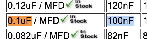
One thing to note, when stuffing I had to convert from .1uF to the nF listed in our component boxes.
This week, since I was going to be doing the same reflowing, I wanted to know whether the problem with my board was the reflowing/AXDL component. To rule that out, I decided to stuff the board first without the ADXL, test programming it, and then try reflowing the ADXL.