choosing a sensor
I'd like to choose a sensor that I'll use in my final project to track a dancer's movement (speed and/or position and/or orientation) through a wearable device. So this week I'm going to make a simple board with an accelerometer to track acceleration and orientation in the x, y, z direction. To keep things simple and attainable this week, I'll be following Neil's helloworld example with ADXL343BCCZ. It will have almost the same components, but I'll replace the ATtiny45 with the Attiny44 so that I have extra pins to add LEDs that can respond to values on the accelerometer.compontents
- ATtiny44
- .1uF capacitor
- 1uF capacitor
- ADXL343
- 10k ohm resistor (x3)
- linear voltage regulator - LM3480IM3
- FTDI connector
- ISP connector
- LED
- LED resistors
designing board
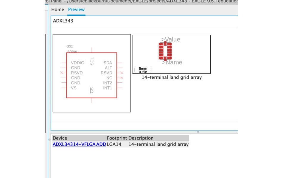
There are Eagle footprints for all the components except ADXL343BCCZ. I'm going to try building a footprint for them (but I'm working under a time crunch this week so worse comes to worse I can pull the traces from Neils board to fit my own ..?). Turn to trusted Sparkfun tutorials for a quick guide on making custom footprints in Eagle.Following the hardware specs in the datasheet ( I feel like I should also check them against an actual part in the lab to make sure that I have the right datasheet or packaging ...), I made a footprint, schematic, and device for the component in Eagle
Trying to draw the board schematic, it was harder then just swapping out the ATtiny45 for the tiny44. I need to understand the ADXL343 better so dive into the datasheet.
Highlights
- reserved@3 can must be connected to Vs (supply voltage) or left open. reserved@11 can be connected to ground or left open.
- chip select, what is it? determines which communciation protocal to go by - I2C or SPI. it has not default state so should always be tied high to Vdd/io (I2C communication) or hooked up to some external controller. So in Neil's board, Vdd/io, Vs, and CS (I think the line on top of CS indicates that it rests low) are all connected, but where is that voltage coming from? Vcc from FTDI goes through regulator (which makes sure voltage stays at 3because ADXL343 has max rating at +3.9V), but I'm confused about the role of R2 and R3 in Neil's board - are those pull-up resistors for the tiny45 pins? Vcc is always connected to ADXL343 but also controlled by PB4 and PB3 with the ATtiny45.
- Allows for both I2C and SPI comunication protocol - there are two different clocks for each I2C and SPI which are SCL and SCLK respectively. I2C (inter-intergrated circuit) overview:
- synchronous commumication that allows for multiple masters to talk to an arbitrary amount of slaves with only 2 wires between each (unlike SPI which requires 4)
- There is a bit of communications overhead - each data message must include one extra bit of metadata (ACK/NACK), but not as much as UART
- Two signals: SCL (clock - speed determined by master unless slaves and clock stretch) and SDA (data). bus drivers are open drain (meaning they pull signal low (cannot drive high to protect devices) and therefore all have pull-up resistors to keep signal high when no device is acting on them - I think this is the reason for R2 and R3 on helloworld board on signal lines between tiny45 and ADXL343).
- basic protocol
- when things are just chilling SLC and SDA are pulled high (hence pull up resistors), then when messages need to be send master wakes up all slaves by pulling SDA low (leaving SLC high) {{note if there's more than one master whichever pulls SDA low first will win}}
- Then, the address frame is sent (can be standard 7-bit address or larger 10-bit) - 7-bit address where master tells slave what to do, then read(1)/write(0) bit indicating if receiving device is reading or writing data frames, and NACK/ACK bit (clock streatching from slave or not - assume ACK which indicates no clock stretching)
- followed by data frames, master continues clock cycle on SCL and data is transfered salve to master or vice versa on SDA (depends on R/W)
- stop condition geneerated by master which are a 0 --> 1 transition on SLC followed by 0 --> 1 transition on SDA with SLC staying high. {{note: this means that data shouldn't be sent on SDA with SLC is pulled high or else it could be interpretted as a false stop}}
- measures both dynamic acceleration and static acceleration.
- can operate with single power supply (Vdd/io only) or double (Vdd/io and Vs) - recommended to have both hooked up and device resting in standby mode with ability to switch on and off measurement mode