
For this week, my goal was to make a bluetooth-enabled chess clock.
Digital chess clocks are still relatively expensive and generally have terrible user-interfaces. These clocks have two functions -- accept button presses from the players, and display time remaining. There are some apps that try to solve this by using cell-phone touchscreen for both purposes, but they are not that responsive for fast chess (blitz) and frantic time scrambles often involve the sort of pounding that is not good for phone screens.
So the idea is to have two buttons send bluetooth commands to a phone. Use the phone screen to display time remaining, and the buttons to absorb emphatic presses from the players.
I decided to use the RN4871 for this project. It seemed really neat and I wanted to try it out.
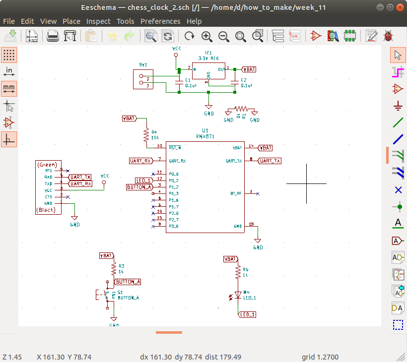
My design was pretty basic, adding two buttons (with pullup resistors) to input pins on the RN4871, and a bunch of debugging LED's with associated current limiting resistors. I had thoughts about using step-response touchpads instead of buttons, but figured it was better to start simple.
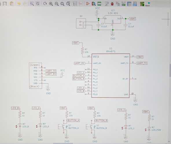
I needed to import schema and footprint for the RN4871 component, which was not in any of the libraries I had installed for KiCad on my machine. I got these from DigiKey. Link
I read through Molly Mason's project page and noticed she recommended thicker than usual traces for the RN4871 pads. I set mine to 0.5mm each leading from the pads for (hopefully) easier soldering.
I probably went a little bit overboard on the LED's here, which I had inteded to be for debugging. I also wanted the board to be able to be powered by 9V battery.
I ended up needing two 0 ohm resistors, but otherwise routing was straightfoward. Routing still took quite a while, though -- maybe two hours? I would like to get faster at this, or find an automated tool that does a better job than I do manually.
Here is the first board design:

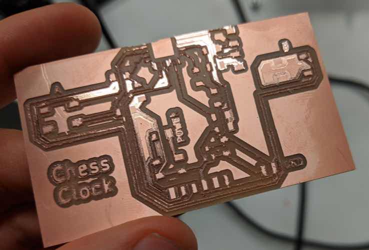
I had milled several boards for various weeks by this point, and all had been fine. The first one I did here looked horrible.
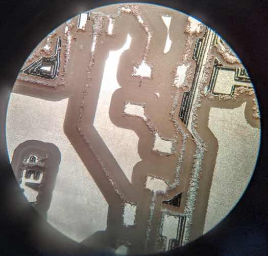
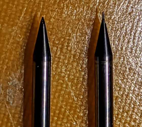
I tracked this down to an endmill, which was broken -- the tip was missing. I took a picture of a new one and a broken one so I could learn to recognize the difference, and then threw out the broken one out.
Second try milling went much more smoothly with a sharp / non-broken endmill.
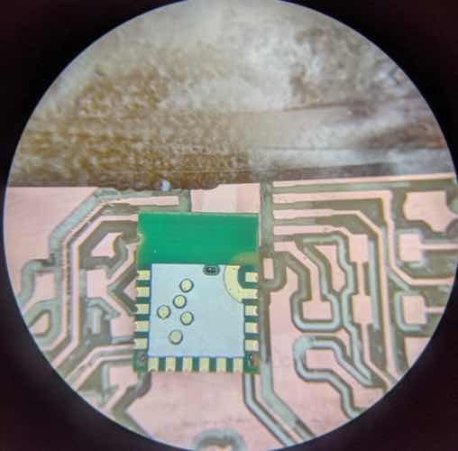
When I was getting ready to solder the RN4871, though, I noticed the small open areas on the back of the assembly and recalled that the datasheet had marked KEEP OUT zones for the top copper plate that I hadn't actually done anything about. To address this, I removed all of that inner area with an exacto knife. This went okay, but not perfectly. Also, there were artifacts on the top edge that I tracked down to some yellow text being treated as an edge cut from the downloaded footprint.
Once I finished soldering, I connected the board to my laptop with an FTDI. Power LED indicator lit up. That was encouraging.
This would turn out to be the only thing this board did, though.
I installed BLE Scanner to look for the bluetooth device. Nothing obvious was showing up, either by name or signal strength. This had me worried.
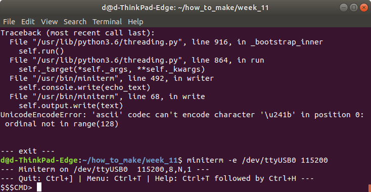
Tried to connect via terminal, using miniterm. I got this error:
FATAL: cannot open /dev/ttyUSB0: Permission denied
Permissions issue was fixed with
chmod 777 /dev/ttyUSB0
I then connected via miniterm. Using the command $$$ yielded no response. I tried a variety of options here, including enabling echoing in miniterm to ensure that this was actually being typed, chagning encodings, and disconnecting and reconnecting my board. Nothing yielded a response. This led me to believe my board was busted. Since I was working from my laptop at home without an oscilloscope or multimeter, there were limited debugging options remaining.
However, in poking around, I realized that the debug / power LED that I had connected to P0_2 had been done with me thinking that the pin would drive the LED high. Instead, the datasheet specified a default of having this led sink into the pin. I wasn't sure if this was the problem, but it seemed plausible. I was also worried that maybe there was some dodgy soldering for the chip, as maybe the exacto-knife removal had made the surface slightly non level.
I decided to design a simplified board that I could re-mill the next morning. I used jused one button in this design, and one LED on pin 0_2 set up as specified in the datasheet.
The idea here is that it may actually be a better chess clock design. If you have two of these, then each player can have one and they can be arbitrarily far apart for convenient location, and allows each player to use their preferred clock hand.
Here's the circuit design:
The v2 board design looks like this:

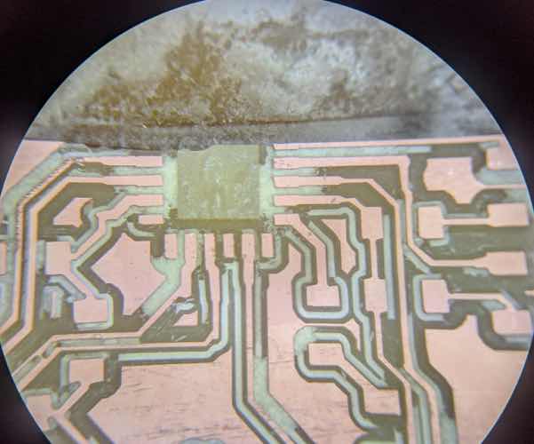
Milling and soldering went smoothly. I included the keep-out section in milling this time, as a separate layer so that I could use fill rather than a limited number of offsets.
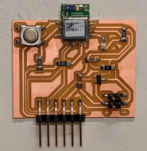
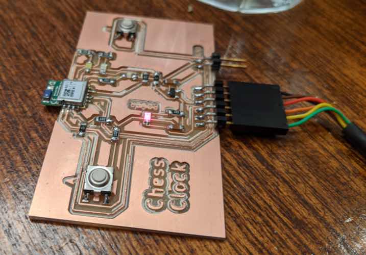
I then hooked up my board to my laptop via FTDI. The power LED blinked nicely in a default, showing the chip was happy. I was also able to locate the device via BLE Scanner app on my phone. These were two good sanity checks to pass.
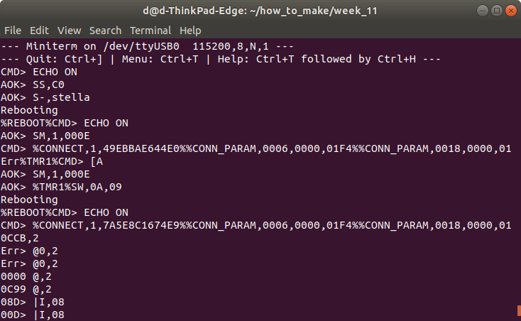
I then used miniterm to talk to the board. First step was to get it to respond to the command string $$$, which asks the chip to begin receiving commands. (This is a little meta.).
I then played with some commands, including setting the device name, sending strings to and from my phone using the BLE Scanner App for Android, setting up the timer and watching it fire, testing the button pin 1_2 for both digital logic levels and analog voltage levels when pressed and not pressed.
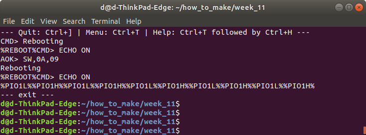
I then set up a little script, based on event handling. I did remember Neil saying that the programming language was kind of horrible, and I can't say he was wrong, but I wanted to at least try a little. I read through the user guide section on scripting and figured out that I could do a hello world for event handling by setting up pin 1_2 as trigger pin 1, and then asking the script to trigger on a change on trigger 1. The syntax for this is a little opaque.
        SW,0A,09  # sets up Pin 1_2 as Trigger Pin 1
        R,1       # reboot to take effect
        WR,06     # start the script when we get a PIO1H event
Here was the debugging output when I ran this and pressed the button several times.
This was as far as I got. If I continue to play with this, I'll make a second single button board and a little Android app that can handle the bluetooth events.