Learning to use Eagle
A new software, a new adventure.
Schematics, rats' nests, and routing.
I found Eagle really intuitive, which was surprising, because I rarely find computer things intuitive! But after getting over the initial panic that I always experience after lecture and recitation, and asking Zach for help with determining what the components are, I found the process quite enjoyable. I first just re-drew Neil's echo board, without adding anything to it. I then made a new version, where I added a button, LED, and current-limiting resistor. I really enjoyed the routing process- there's something intensely satisfying about finding paths between elements on the board, drawing them, and fitting them in so they don't cross anything else. I then downloaded the python script to create a .png file of the traces and the outline to use at the mill, ran it, and got my first error. I guess I should have realized that things were going far too smoothly to be real, and that I was being overly optimistic to believe that the whole week's work would be this easy, but I then spent the next several hours trying to figure out what was going wrong. The error was especially confusing, because it worked once on the board that didn't have the LED, but then failed the rest of the times; on my re-designed board, it consistently came up with errors. I re-drew the boards twice more, just to see if there was something wrong with the design, but no luck. After a night of rest, I looked more closely at the script, the error messages, and the strange files that were being generated by the script. I noticed that while the script was supposed to look at several layers of the .brd (board) file, compile the images, and generate a monochrome .png, it seemed to be making layers off of the schematic. I'm not sure why it was doing this, but after I deleted my schematic (which otherwise, sounds like a bad idea), the script worked fine and gave me my hard-earned .pngs. Whew. Design files:
 First Eagle experience: just copied Neil's echo board.
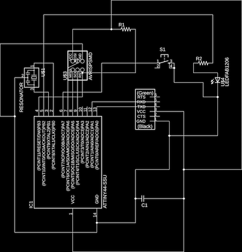
 Making my own schematic, this time, adding a button and an LED. The schematic's a bit unsightly, but it worked!
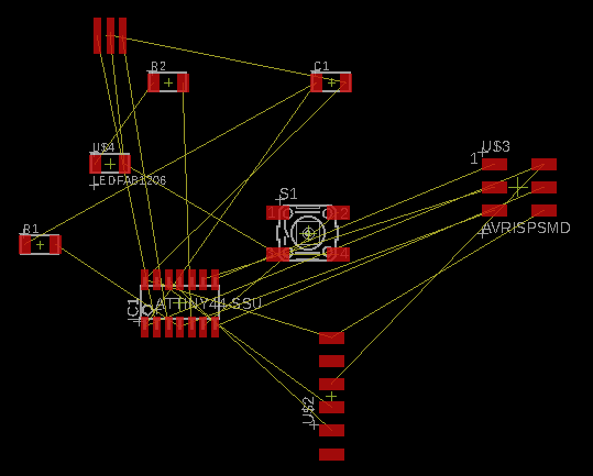 The pre-routed board, aptly named "ratsnest".
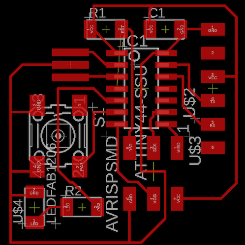 The routed board. I actually really loved the routing process!
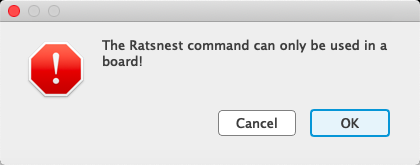
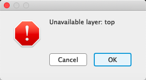

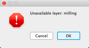

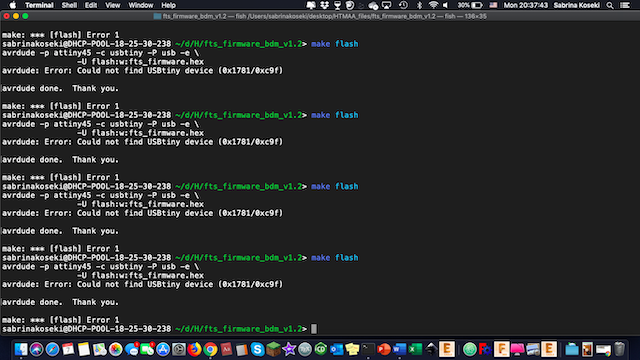
 The slew of errors that materialized when I tried to export the .pngs of my board.
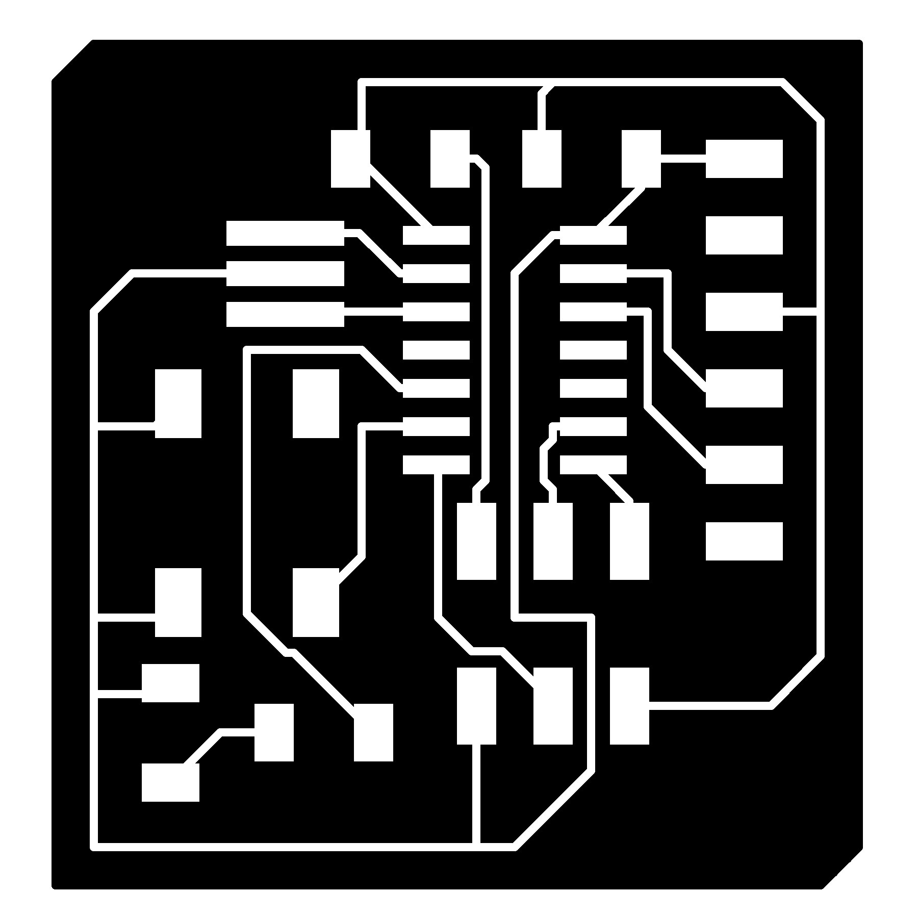
 An intermediate file produced by the confused python script. Looking at this helped me realize that the script was mistakenly looking at the schematic, not the board.
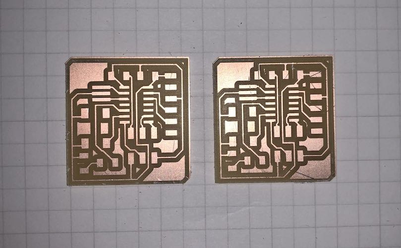 The milled boards. I made two just in case I damaged one during the soldering process (which I, unfortunately, did).
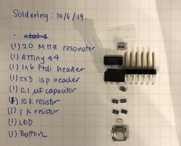 The components I soldered on to the board.
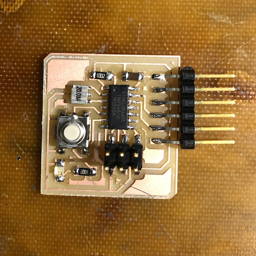
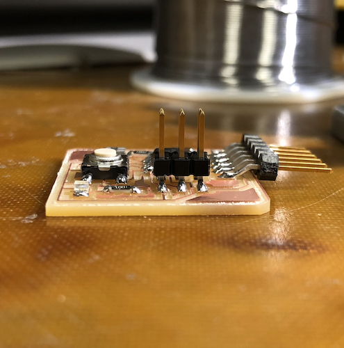 The stuffed board. Unfortunately, I forgot to move the FTDI header more onto the board to strain-relieve it. Something to remember next time.