Final Project Ideas
First Ideas
The first week's assignment was to think of potential final project ideas. Before the beginning of the term, I had thought a little about building a railgun or some kind of drone. Check out Week-1's page for more details regarding the railgun. I soon realized that the railgun was not encouraged to build in the EDS lab, unless I build a small one. Also, I could not think of very many embedded stuff that could be added to the railgun. Therefore, it did not feel like a suitable final project idea.
The idea of making a drone sounded very cool in principle, however I could forsee the humongous amounts of problems I might run into especially since I had minimal background working with drones. Making a drone could be a standalone semester long projcet, not a final project for a class.
Settling on a New Idea
I had heard from a friend that detecting and predicting patient falls in a hospital is a big problem. The existing technology works only minimally and is very unreliable, and building a nice technological solution is not easy given minimal research has been done in this sector. I realized that I could build an embedded system which could detect some kinds of patient falls. The device containing the embedded system would be in some wearable form that the patient would wear. This device would record the movements of the patient in the form of accelerometer (part of the embedded system) readings, and raise an alert whenever the device thinks the patient has fallen down.
This sounded like the kind of project that was well within the scope of this class. Having, built a simplistic model, there is also enough room to make further additions to this project. Things like a sophisticated alert system, reducing false positives and so on could be further additions that could be made if more time was left.
Developing the Idea
3 Major Questions
Even before I had fully setteled on the idea, three questions came to my mind.
- What is the exact nature of the patient falling problem? To be more elaborate, how do patients fall; what are the mechanics of the patient before, during and after the fall; are there different kinds of falls; how frequent is one kind of fall compared to the others and so on.
- Which part of the body would the wearable should the wearable go on?
- What would be the simplest embedded system that I could come up, that would just solve a small subset of the problem at hand?
Nature of Patient Falls
I came across a PMC research paper that answered almost all the questions I had had. There are multiple fall types which are all prevelant. The most important typs are collapse (33.9%), sliding onto floor (23.0%) and fall from height (6.6%). The most common activity at time of fall is ambulation (19.1%), getting out of bed (10.9%) and sitting down or standing up (9.3%). The common mechanism of fall were losing balance, slipping or tripping and dizziness or fainting. These stats give me a nice fall mechanism to focus on to start off, namely fall due to collapse, either while standing or walking.
Where does the wearable go?
The fall detection device would heavily rely on its accelerometer readings. Since falling is a mechanism where the entire human body falls to ground, the ideal situation would be where the accelerometer only captures the motion of the entire human body as a whole. Having the device as a wrist wearable, for example, would heavily clutter the accelerometer readings due to secondary motion of the arm/wrist. That's becaue the arm/wrist is a part of the body that can move constantly even when the entire human body might be in a state of almost total rest. A better place I had thougt would be the shoulder. The shoulder part ususally moves along with the entire body and its a place where the device could be placed without sacrificing too much patient comfort.
Simplest Embedded System
The simplest embedded system would consist of a microcontroller, an accelerometer, an LED and some other supporting components like the crystal clock. The microcontroller would take its input from the accelerometer, analyze the input and if the readings detect a fall, outputs alerts through the LED (by flashing the LED maybe). This would be a very simple embedded system. To start of I am thinking of using building a similar system, however instead of staring of with just an accelerometer, I plan to start of with a BNO055 (a chip that has accelerometer, gyroscope and magnetometer data). The reason to start right here is, there seems not much reason to spend time with the simple accelerometer and then move onto the sophisticated BNO055 when I could just start with the BNO055.
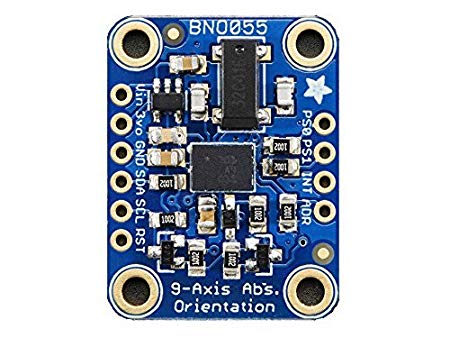 Adafruit BNO055 Absolute Orientation Sensor
Planning the Next Steps
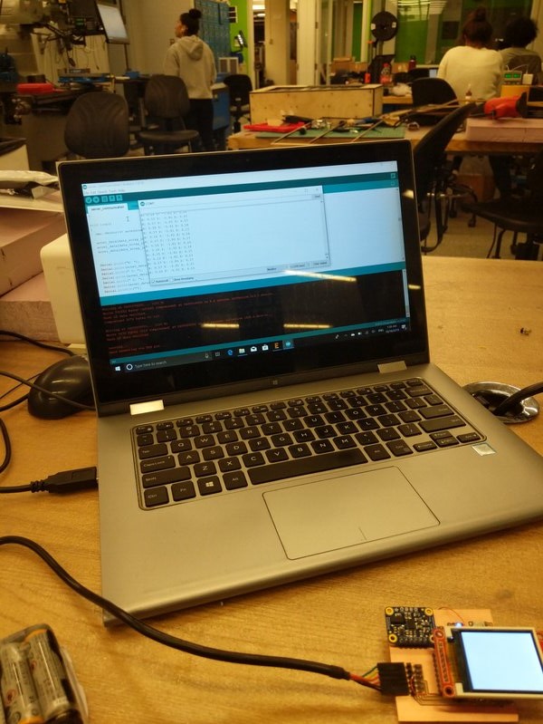
At least to begin with, instead of making the device using a simple microcontroller like the ATTiny, I decided to use the ESP32. The ESP32 is a chip with a microcontroller, WiFi, Bluetooth and many more which makes it suitable for rapid building. I had an ESP32 already from a project in another class. I also had an OLED screen to which the ESP32 could print to, so I decided to use that to begin with. Since the setup with the ESP is a complicated one with many pins and wires, I did not just want to make a PCB to begin with. It would be easier to work with a breadboard. My ESP32 and the OLED screen were already on a breadboard. I decided to use the same breadbord for prototyping. I then planned the next steps for building the Fall Detection Device.
- Add the BNO055 to the circuit and read accelerometer data
- Setup a remote server which the ESP32 Wifi can send data to
- Add functionality on the Arduino side to send data to server
- Provide battery power supply to the circuit board
- Perform data collection by strapping the mobile board onto one's shoulder
- Analyze the data and build a model to predict the human state based on the data
Retrieving Data from the BNO055
The ESP32 has very good support Arduino support, and without hesitation I decided to use Arduino for my project. Although Arduino code is bulky and prone to bad performance, for my situation it works well. The ESP32 has enough memory to hold all the bulky Arduino code and its fast enough to process the BNO055's reading on the order of miliseconds, way too fast than my requirements. I hooked up my BNO055 Absolute Orientation Chip to the ESP32 and started retrieving accelerometer data. This process is better descibed in input devices.
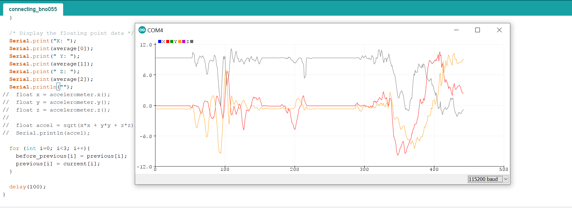 Acceleration data
Data Collection
Setting Up Data Pipeline
I needed to visualize the accelerometer data to get a sense of how the accelerometer readings change as a person is walking, lying down or falling. For that purpose I needed to setup a data pipeline first. The idea was somehow I would specify what state the person wearing the device is in and then the accelerometer readings would get recorded and sent to an online database. For this, I setup a remote server using Heroku where data could be sent and stored. Networks week goes into the details of setting up this pipeline. In essence, data is collected by the ESP32 in a buffer and when the buffer is about to be filled, that data is transmitted to the Heroku server where it gets stored. The data can then be downloaded using a GET request. All the POST and GET requests that can be performed can be found here.
After this pipeline had been set, I had to figure out a way to tell the device of the state the person putting it on is so that it could transmit labeled data. I figured I would do that using button presses within a certain interval. One button press means stop transmission, two means walk mode (and start transmitting data), three means still mode and four means fall mode. I wrote a function button_presses(uint8_t input) that would keep count of the number of button presses within a certain time. The function definition can be found here. When setting up this functionality, I got some weird errors that would assign values randomly to some variables. After a few hours of debugging, I realized the errors were because I was overwriting an array.
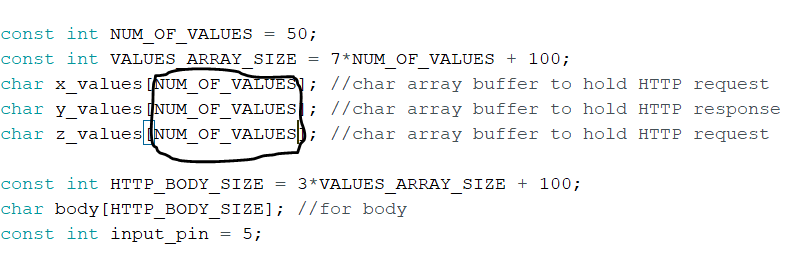 Array I was overwriting to
Collecting Data
I strapped the breadboard around my shoulder using tapes and started collecting data. I first specified the state and then performed the corresponding action. After a few seconds I would then stop the transmission. Below is an example of when I collected data for falling state.
Patters and Inference
Visualizing Data
After I was done with the data collection steps, I plotted the results. Almost for every fall case, there was a large spike, for walking there was osicalltory behavior and when still, there were only few fluctuations, just like I had predicted. I used a python script to generate these plots.
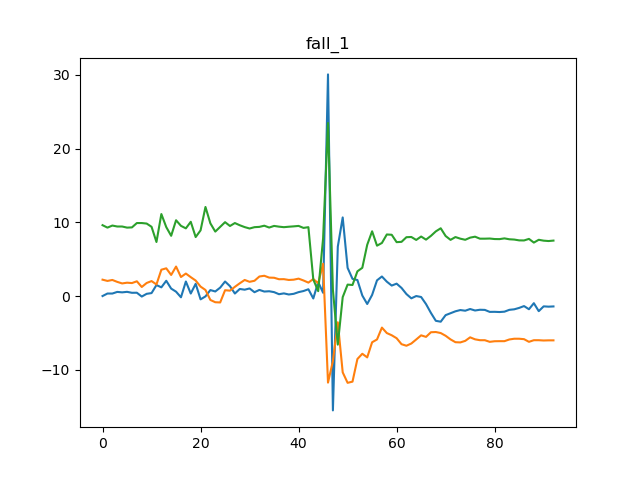 Accelerations along 3 axes when falling
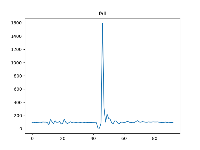 Total acceleration squared when falling
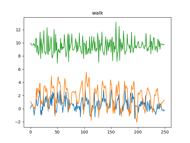 Accelerations along 3 axes when walking
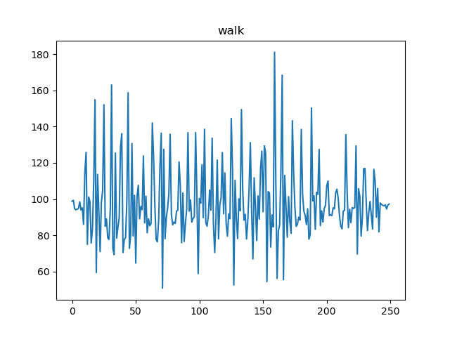 Total acceleration squared when walking
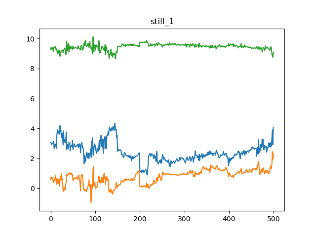 Accelerations along 3 axes when still
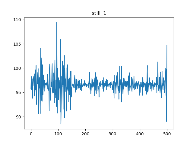 Total acceleration squared when still
Inference
Once these plots became available, I thought of a simple algorithm that would detect all these different states. That relied on the standard deviation of the acceleration values. Given a small timeslot, the standard deviation of acceleration values when still is very small (below 0.07 for z-axis), when walking is average (above for the z-axis) and when falling is very high (above 33 for the z-axis). I calculated these standard deviations. After that, for prediction, I would only need to calculate the standard deviation values for a certain time range. And based on that standard deviation, one could infer the human motion state. In my final script for the fall detection device, I exactly do that.
Makint the Final Board
Schematic Desgin
Until now I had been using the ESP32 breakout board on the breadboard, however to fulfill the requirements of this class, I would have to use the non-breakout version of the ESP32 on a PCB. The starting point was Neil's ESP32 WROOM circuit. I first built an Eagle schematic precisely for that board. After that I started adding my own components to it, buttons, female header for OLED screen, slots for the BNO055 Absolute Orientation sensor and so on. I also added added a switch that would toggle between the power supply from battery or from the FTDI cable. This would ensure we are not giving power from two ends.
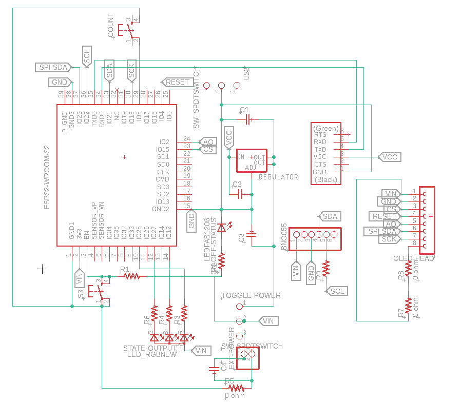 Schematic (after correction)
Board Design
This took a long time. I had made a very complicated circuit with lots of pins. Also, as I made the board, I wanted to make it as small as possible which made component placement and routing even harder. Once again, I followed what Neil had done on his ESP32 board. Taking that as reference, I first placed all those relevant pieces in positions around which he had put the components. Then I went ahead and started putting the components I had added. It took a very long time. I used the bottom layer extensively, and I had around a ten eight vias and four 0 Ohm resistors in my circuit by the time I was done. Later I realized, I had not made some mistake in my schematic and my routing. I had checked 3 times before I moved on to the next steps, but I still made those mistakes.
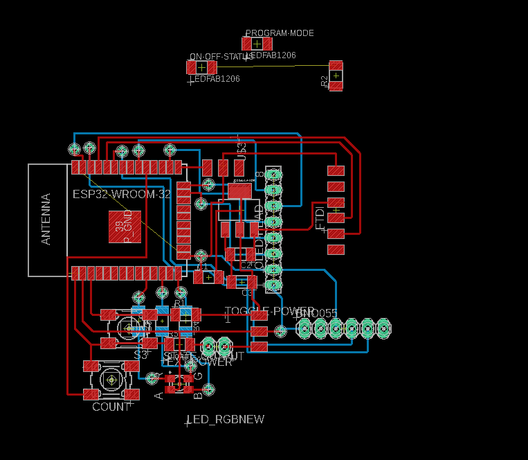 Board Before Completion
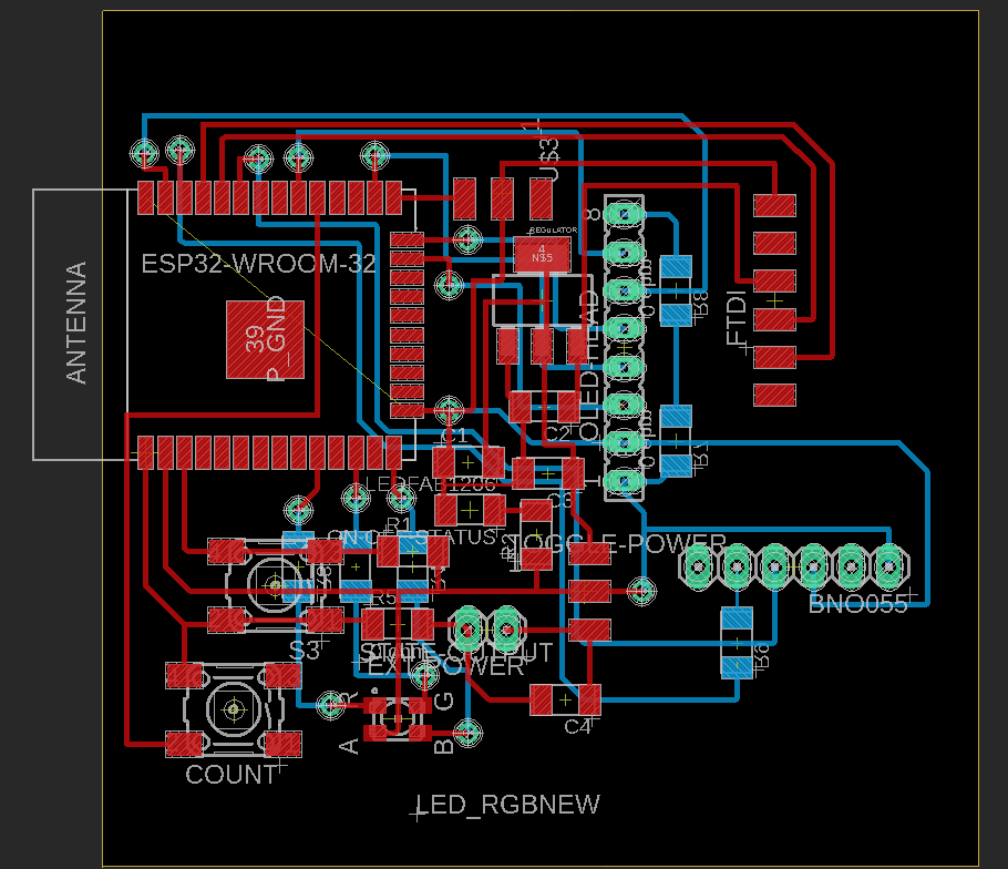 Completed Board (after correction)
Milling
I used the othermill to mill my boards since it is much easier to deal with. I had two failures while milling the board. On the first go, the I used an old 1/32" endmill and the traces were terrible. I performed another mill, however that time around I did not set the 1/32" mill to be conservative, so it did not produce the traces correctly. As they say, third time is the charm, the third mill worked out pretty well, and the board came out well.
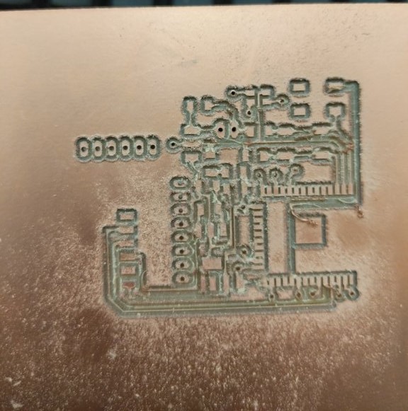 Board after first mill
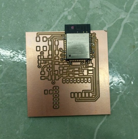 Board after third mill
Mistakes
I had spent a long time on routing and milling the board correctly, nearly two days that I was in a rush to solder things. Without realizing I soldered the ESP32 even before putting in the rivets. The vias were right next to the ESP32, so I could not put in the rivets without tampering with the board. And it was too late to de-solder the board. Anthony suggested I just put wires through and solder the boards. This was a nice idea, but I did not realize how this could go wrong. When making wires as replacement for vias, I solderes on end and ended ripping off the traces. Since there were so many vias, even if I was super careful, I was ripped multiple traces. I fixed some traces by making solder bridges and others by adding jumper wires. I also realized I had shorted two pins of the ESP32. Anthony helped my desolder it. Soon enough there was a board that looked all good to go.
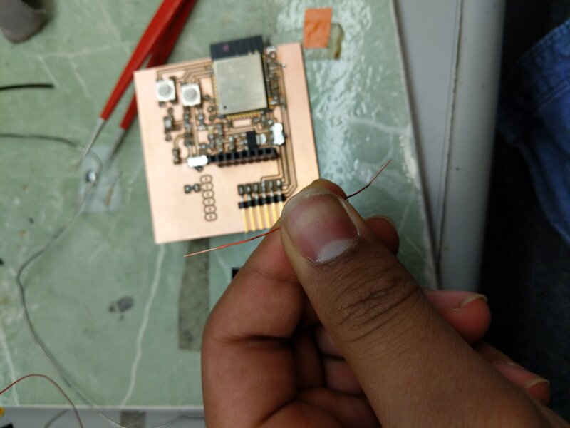 Magnetic Jumper Wire
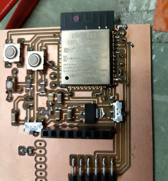 Soldered Board
Programming the ESP32
Programming the ESP32 should have been really straightforward, however, it was not so. The board would not program when I or Anthony tried to program it. I went back to check the board, and yes there was on mistake. One of the vias did not seem to work, so I added a jumper wire. That fixed that issue but still the board would not program. I then performed another check, and the output from the 3.3 V regulator was about 4 volts. That did not seem right. I and Anthony checked for a while and realized, I had made an error in the board design, and not connected one of the legs to ground. I added another jumper to fix that. After that, the board started to program. However, it still did not program consistently. If I tried programming 5 times, it migth program once. It would also show nothing on the serial monitor after the board had been programmed. I was simply exhasusted at that point. I had been fixing things for the entire day, had worked on this board for the last 4 days and things still did not seem to work.
Almost Always the Programmer is Wrong
I thought maybe I was missing something, maybe some chip in my circuit is flawed. That made me feel worse since if that was the case, I could do nothing about it. I took a break of about 90 minutes and then came back to work. This time around again I checked all my connections and figured, yes it was my fault. For the 20th time, I had a bad solder. The ground pin was not quite soldered well and that's why it did not program consistently or run. I fixed that solder and the board programmed like magic.
 Board Programmed
Many Mistakes
Turns out I had many other soldering erros too. However, this time around I kept my calm. If anything did not work, I went back and checked my circuit and made things work. I got pretty good at debugging.
Uploading Inference and Testing
I uploade the inference program and started testing it out. Almost immediately, that started working. The only problem was, with the inference program, nothing would print on the OLED screen. This was one bug I could not fix. However, in my final product, I had thought of detaching the OLED screen anyways and making the RGB LED signal the output. I configured the RGB LED to display this result. More on how I configured the RBG LED can be found in output devices. The RGB LED worked well.
Packaging
The board had almost everything I needed to for the device to work. Nonetheless, if it were to be a decent enough wearable it should go into a nice package. I could 3D print a case, but I was short on time. I decided to laser cut a box for it. I designed a box in Fusion360. I then went ahead and exported each file as DXF and laser cut the 3mm acrylic to make the sides. I took the face out, and assembled them to make the box. The pieces fit loosely, so I hot glued them into place.
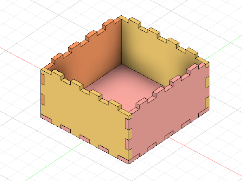 Box CAD
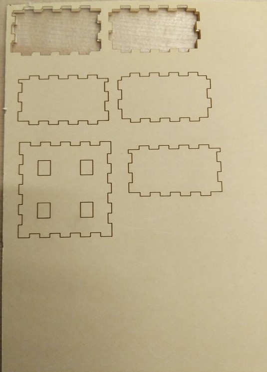 Laser Cutting the Acrylic
After that at the bottom, I hot glued, the battery holder. I also had holes in the bottom layer through which strings could go. These strings would be used to tie the device around the subject's body to keep the devide in place on the shoulder.
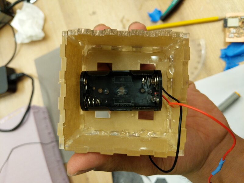 Battery Holder in the Box
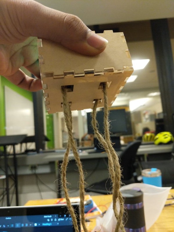 Strings in the holes
Finally, I made four small pillars out of cardboard that I placed in four corners of the box and hot glued them. I then, attached my board to the pillars using double sided tape.
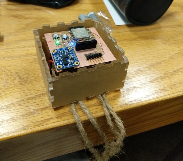 Device Ready to Use
Final Test
I performed the final test of the board back in my dorm room and it worked as intended. In the video below, it can be seen that the LED changes changes color appropriately. It might take about a second to change the color to the appropriate state, green when still, blue when moving and red when falling, however it does do that. Note also that once it turns red, it stays red. This is to alert that the person has fallen down. Only after rescue and pressing a reset button can the state be restored. As long as the LED is red, the person is in a bad state, having fallen down and not recovered themselves, or not been rescued.
Device Operation
As soon as power is provided to the device, it starts operating. It does not require WiFi or any such featues to operate as of now. The RGB LED changes color based on the human motion state. If it turns red it will remain red indefinitely until the reset button, not the reset program, is pressed upon which the device assumes you are in still position and resumes from there.
AfterThoughs
I got to learn a lot doing the final project, especially realized how many things can go wrong. I think I did a pretty good job with making the board work. I am also proud of the data collection methods I applied and the inference algorithm I used. I think I could have done a better done of packaging. My error there was I waited till the last moment to start packaging. I could have done some parallel processing there. I believe, enclosing the board well, and then shiriking the volume of the board would make this device more portable and usable. At this point, the battery takes up a huge volume. If I were to work on it to further improve it, I would use cell batteries that are much smaller. Finally, I would replace the strings with something like Velcro, or have the device come attached to a shirt that could be put on.