Learning the Theory
Understanding AVR Programming
Harrison mentioned that the "Make: AVR Programming" book explained AVR programming very well, so I started off by reading that book. I had my confusions around the process of code compilation, the use of programmer and so on. This book laid out in detail a step by step procedure.
- Write your C code for the microcontroller in your favorite text editor.
- Compile your code using the
avr-gcccompiler - If you have multiple C files and dependencies, you can make use of the
makefileto keep things simple - You need a software that talks to the microcontroller,
avrdudeis the software of choice usually - Lastly, you would need a programmer that sits between
avrdudeand the microcontroller
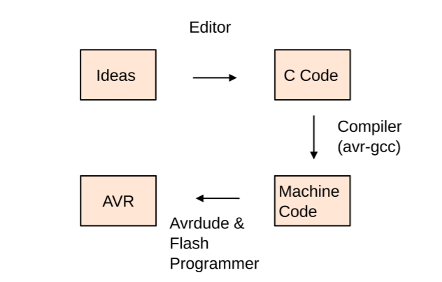 AVR Programming Workflow (Source: "Make: AVR Programming")
Going Down the Microcontroller Rabbithole
Two weeks ago, I had done some research and learnt more about microcontrollers, peripheral interface protocols and other high level stuff. This week, I wanted to get deeper into understanding the microcontroller. "Make: AVR Programming" was a good lead into learning about microcontrollers. Then I started reading the ATTiny44's datasheet. Very soon things started getting complicated. I bounced around from article to blogs understanding the different components. Things like Pull-Up Resistors, Differential Signals, microcontroller's different pin types and so on. It felt very overwhelming. Although, I had learned a lot, in reality, I had only started to understand the world of embedded systems.
Building a Simple Embedded System
Schematic
I tried to think of creative circuits I could build using the microcontroller, buttons and LEDs. Just using LED as output and button as input, I could not think of too many creative ideas. Any creativity would have to be expressed in the software side. Last week, my LED had been in series with a button and turned on whenever the button was pressed. This time, to enable some logic into the system, I decided to connect the LED directly to a microcontroller pin. I also connected a switch to another pin. Since I already had most of the schematic from the Electronics Design week, I simply changed the schematic a little to achieve my goal. Next, I went on to the board file.
Board Design
Here too, most of the work had already been done. I just needed to re-route the new changes. I realized I had to add vias to make the circuit possible. I actually felt very excited about adding vias and making 2 layered boards. I added my vias and completed the routing. I also wanted the outline of the board to be circular, so I created a circular outline.
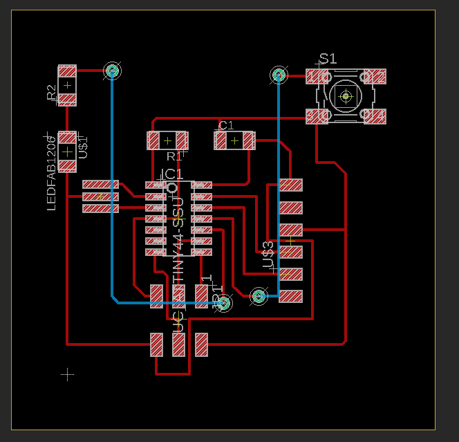 2 Layered Board
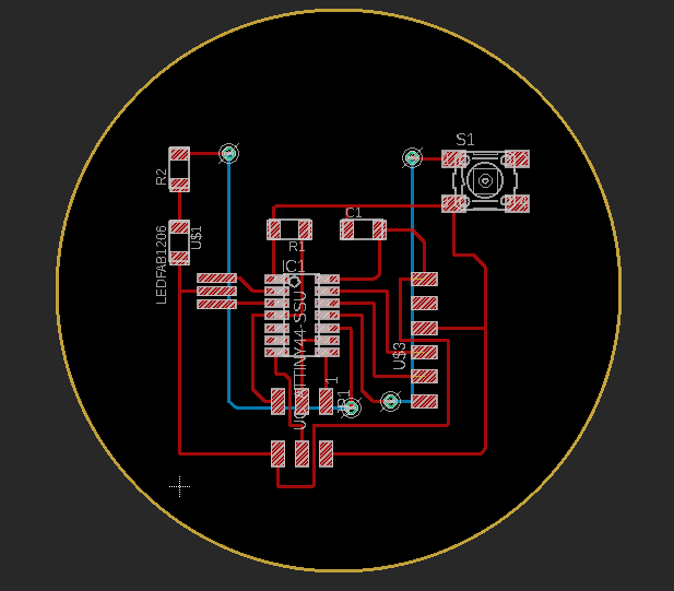 Circular Outline
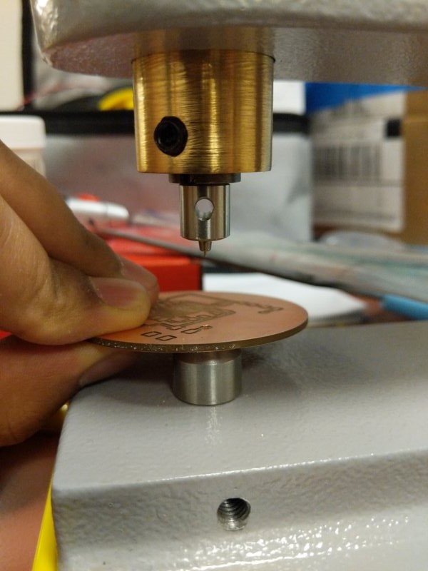
Milling the PCB
By now, I had gotten the hang of using the milling machine. I strongly preferred the OTHERMILL over the SRM-20. For a 2 layered board, I had to use the OTHERMILL anyways. I opened my eagle board in Bantum to print, but it only showed the outline and the holes, no traces. This felt very strange. If I made the outline with a bunch of lines that formed a rectangle (not a rectangle drawer itself), the traces showed up. My guess was, since the circle I drew had a fill, it shadowed the traces. Same would happen if I drew a rectangle object, but if I used lines to make a rectangle, there was not fill and it worked.
Anthony suggested that I could use gerber files to get around this issue since Bantum, OTHERMILL's software, accepted gerber files too. He taught me how to generate the gerber files. You needed a specific Eagle Cam Job file for Bantum to generate gerber files supported by Bantum. This page on Bantum's website has the link to the Eagle Cam Job file as well as information regarding using it. I was soon able to generate my gerber files and start the milling process. Since I was milling a 2 layered board, I had to flip it to mill the other side and then cut the outline.
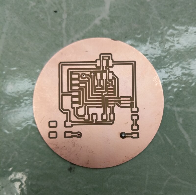 Milled Board Front
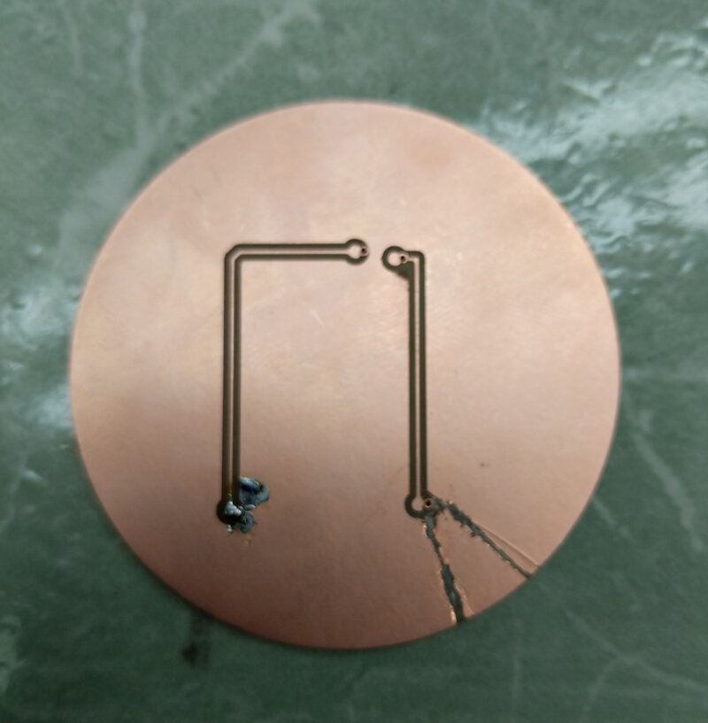 Milled Board Back
Rivets and Soldering
When I had flipped the board, I did not align the right corners, instead I still had the left corners aligned. Therefore, the bottom part of the board was slightly mis-aligned. I fixed that using a knife. I then added rivets into the vias. Then I went on and soldered the components in place. I used hot-gun to solder the larger componets.
 Adding Rivets to Vias
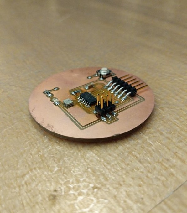 Soldered Board
Programming the Board
I had the option of coding in Arduino or vanilla C. The "helloworld.c" program Neil had written looked very complicated and I thought, for the time being, I should stick with Arduino. Setting up the Arduino for ATTiny44 was relatively easy. High-Low Tech's website walks you well through this process. I also had to get the avrdude for my computer. The Software Installation section on Brian's USBTiny Tutorial walks you through the process of getting avrdude on your system. After setting up my Arduino, I wrote a simple program to flash my LED whenever the button was pressed. Alas, you cannot enable pull-down on ATTiny. I had conned my button to VCC, so I could only make the input work if the ATTiny pin was configured in pull-down mode. I could still program my LED to do some cool stuff, like blink every other second. I programmed it so, and it worked!
Arduino Code
                    const int ledPin =  3;      // the number of the LED pin
                    // variables will change:
                    int buttonState = 0;        // variable for reading the pushbutton status

                    void setup() {
                      // initialize the LED pin as an output:
                      pinMode(ledPin, OUTPUT);
                    }

                    void loop() {
                      // switch buttonState in every iteration
                      buttonState = (buttonState + 1) % 2;
                      // check if the pushbutton is pressed. If
                      it is, the buttonState is HIGH:
                      if (buttonState == HIGH) {
                        // turn LED on:
                        digitalWrite(ledPin, HIGH);
                      } else {
                        // turn LED off:
                        digitalWrite(ledPin, LOW);
                      }
                      delay(200);
                    }