This week we learned how to add output capabilities to microcontrollers.
This week, our goal was to add an output device to a board we designed. I decided to try to add an LCD display to an ATTiny44A board so that I could read ambient temperature (see Week 8 and then display it on the LCD monitor instead of needing to connect to a computer to read the temperature.
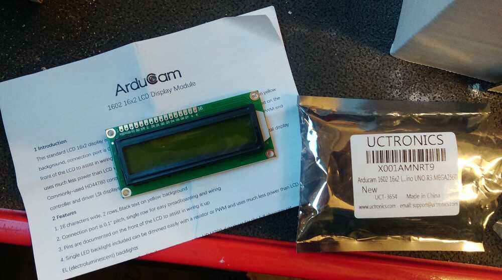
Before I started, I found the LCD I wanted to use and read some documentation. In the Harvard shop, I found some 16x2 LCDs that appeared to be basically the same as the Fab inventory LCDs, but physically bigger. I liked the size increase as it would make the screen easier to read, but the identical architecture meant I could use the same documentation and tips as for the official Fab inventory LCDs.
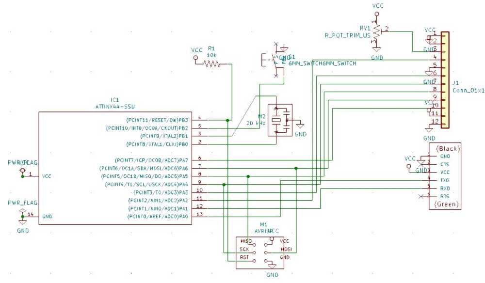
I started with my KiCAD schematic from the Hello World board, removed the LED, and added a 12-pin connector to connect to the LCD. I used a couple of helpful resources to figure out what pins need to be connected to what: A guide from Adafruit to wiring up a standard character LCD screen and a datasheet for the 1602 LCD module that actually includes pinout information. I decided to use pins A2 and A3 for RS and E, and pins A4-A7 for the DO5-7 data pins. This allowed me to keep the serial communication on A0 and A1, and leave the B port open for the resonator, reset pin, and button. The LCD came with a poteniometer to vary the contrast of the LCD (see more on this later), so I also added this to the schematic at the proper point.
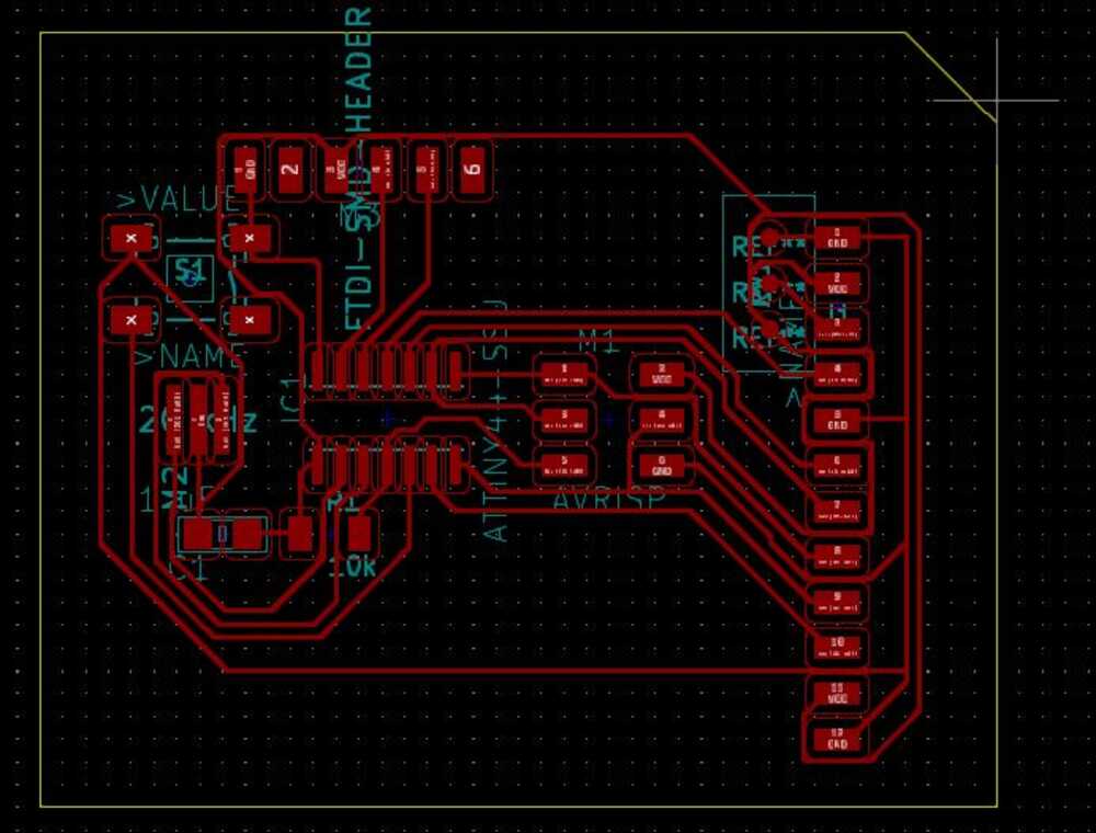
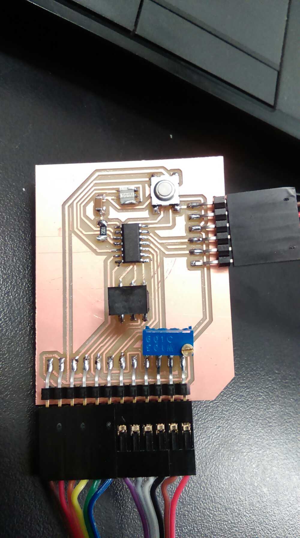
In order to add the 12-pin header and the potentiometer to the layout, I had to find their footprints. I found the footprint for the potentiometer in the built-in KiCAD library, and then modified it a bit to decrease pad size (so I could route traces between the pads).Since it is a through-hole component, I also had to make holes in the board for the leads to go through. The default footprint had vias set up, but I wanted my holes to be smaller and didn't want to use the back copper layer, which was the default. I therefore set the pads as front copper layer, removed the vias, and instead added in small circles on another layer that would be milled as pilot holes for making the through holes. For the 12-pin header, I just copied the 6-pin FTDI header from the fab library and copied it vertically for a total of 12 pins.
Routing the board took a rather long time, mostly just because I was too stubborn to use a 0 Ohm crossover resistor. After hours of trying to route all of the traces without crossovers, I realized that I could actually use the button as a crossover, since it has two pairs of electrically connected pins. I didn't know how to tell KiCAD that the button had internal connections, so I just added back layer pads to the button footprint, connected the paired pins on the back-plane layer, and then didn't actually use this back layer for output.
I finally exported the board outline as one SVG, the front copper traces as another, and the holes for the potentiometer as a third SVG file.
Having learned from previous weeks (see Week 4), I used the version of the local mods server that takes SVG files as input. This saved a lot of file-conversion trouble. I first cut the traces, then, with the same tool, cut the pilot holes for the potentiometer. Since the tool diameter was too large to cut all the way through without removing the pads, I just cut about twice as deep as the traces were cut. I finally switched to the 1/32 endmill and cut the outline.
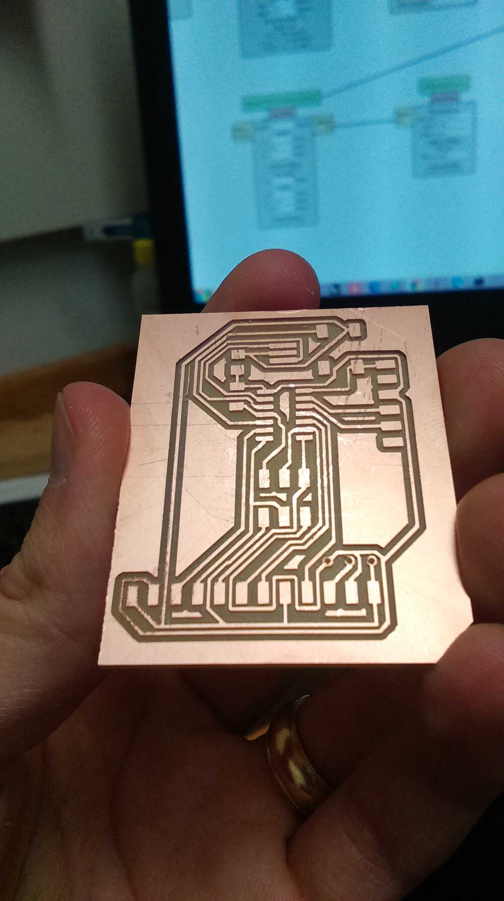
I then soldered the components onto the board. In order to solder on the potentiometer, I had to widen the pilot holes to accomodate the leads. I did this by manually twisting a 1/64 ball-endmill into the pilot holes from both sides so that the holes would just connect through with enough width for the leads but without removing the pads completely (some of the pad was removed, but enough remained for soldering). The rest of the soldering was straightforward.
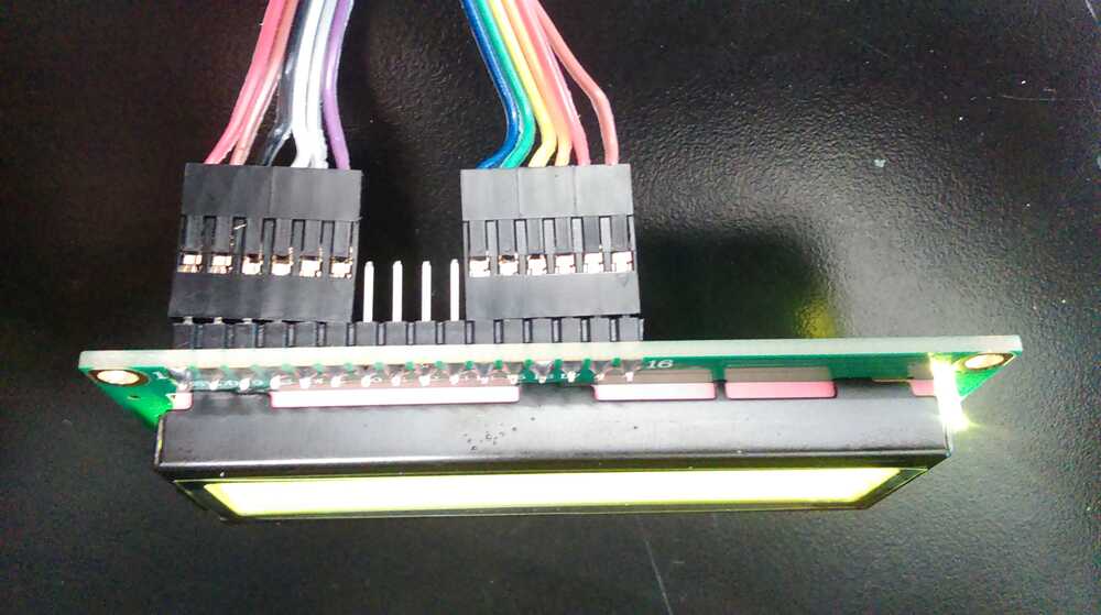
To connect the LCD, I soldered a 16-pin header to the LCD. I had designed the board under the assumption that there would be flat ribbon-cable connectors easily available for connecting a cable to my 12-pin headers. Unfortunately, that was not the case, so I had to manually put four six-pin crimp headers onto the ends of some 12-strand rainbow cable. I did learn how to crimp these using needle-nosed pliers though. I would recommend sticking with the 2xN connectors that Neil used in his examples, since they are much easier to use.
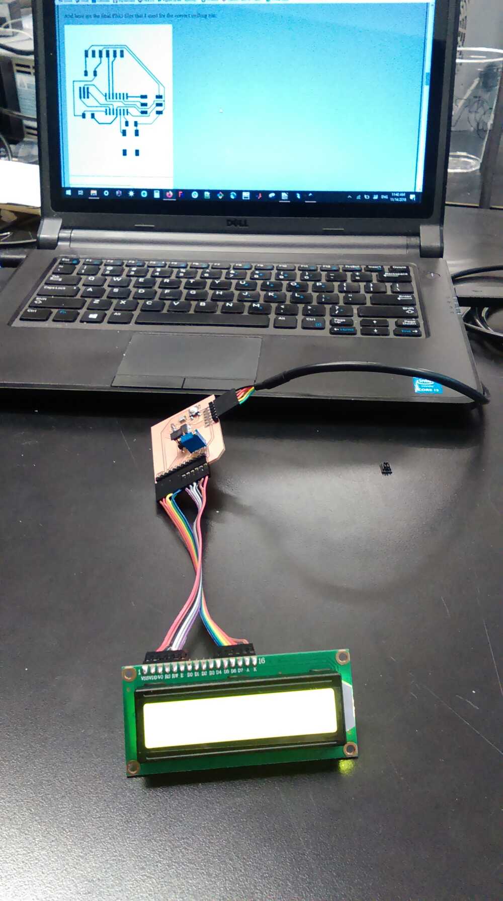
Finally, I tested my cable with an ohmmeter, and then plugged the board into my computer using a 5V FTDI cable. The LCD backlight turned on, which was a very good sign!
My idea was to start with the code from my Week 8 project, in which I had created an interrupt-based framework that would allow the controller to read and send temperature readings. This week, I wanted to modify the code so that the temperature would be displayed on the LCD instead of being sent to the serial connection.
First, I started off by testing that the ATTiny was correctly installed and able to communicate by simply programming in my week 8 temperature reading code. Since my board design was so similar, I only had to remove references to the LED in order to adapt the code. The board passed this test, though I noticed that the calibration was off. This was not surprising, as the temperature readings aren't consistent across boards and need to be individually calibrated.
I then tested the board using Neil's "Hello World" code for the LCD. I simply had to modify the pin assignments to adapt the code to my board. When I ran this test, however, no text appeared on the board. For several hours, I debugged, using an oscilloscope to view the signals on all of the LCD pins, but everything seemed normal. Only when I read the datasheet more thoroughly did I discover that the voltage coming from the potentiometer gives the highest contrast at 0, not 5V, so the contrast increases as the voltage on V0 decreases. I had assumed that the voltage on V0 should be proportional to contrast, so I had turned the potentiometer way down, so that about 5V were coming in on V0. As soon as I tried turning the potentiometer way up, so that V0 decreased bast ~2V, the Hello World text appeared on the screen. The display had been working the whole time; I just couldn't see it because of the incorrect contrast settings.
(The 'd' was changed to 'z' because the low 'nibble' (4-bit data unit) of the last character entered remains on the input pins for ~1s, so I was using an oscilloscope to check whether the bit pattern on the data pins changed correctly when changing the character from 'd' to 'z').
My board does have one quirk: Because some pins are used for both ISP programming and LCD control, leaving the LCD plugged in while programming the board can mess with the LCD state. It is therefore necessary to disconnect board power, unplug the LCD, connect board power and program the board, disconnect power again, plug in the LCD, and finally reconnect power. Interestingly, leaving the programmer plugged in while the LCD is operating causes no problems, and in fact the indicator LED on the programmer provides a useful indicator that data is being sent to the LCD. This was not a design feature, but is an interesting and useful side-effect.
After resolving that frustrating issue, I moved on to my actual desired functionality. I copied over the character, string, and command write functions to my Temperature reading code, copied over the pin setup information, inserted the setup code into my main routine, and then inserted code to send my temperature readings to the LCD instead of to the serial output.
It wasn't quite that easy though. In Neil's lcd_putcmd() routine, he had taken the shortcut of simply
assigning the command byte to PORTA. The effect of that is to set the desired pins while clearing all others.
This assumes, however, that none of the PORTA pins are in use for other purposes. Since my board still uses two PORTA pins
for serial data, this shortcut would result in my serial data interrupt being triggered whenever a command goes to the LCD.
I therefore replaced the line "PORTA = lcdbyte;" with the two lines
PORTA &= (~(DB4 | DB5 | DB6 | DB7 | E | RS));
PORTA |= ((DB4 | DB5 | DB6 | DB7 | E | RS) & lcdbyte);
The first line clears all of the LCD output pins, while the second line sets the desired pins.
Next, I checked the datasheet for the minimum time between commands and found that I could safely decrease lcd_delay to 5 ms with a good margin of error left over. This would let my board spend a little less time sending commands. I also wanted to be able to display messages that weren't from flash, so I had to modify the lcd_putstring() routine to read a normal string instead of a flash string. Finally, I checked the datasheet to determine the character code for the 'º' symbol. Although the character codes for the first 128 characters follow standard ASCII, the second 128 characters do not follow standard extended ASCII, so a string including non-core-ASCII characters might not translate correctly. From the datasheet, I determined that the 'º' symbol corresponds to the value 223.
With all of these changes made, my code outputs a default greeting until the user presses the button on the board (or sends a 'T' from the serial connection, although the board can function without a serial connection). When triggered, the board takes a temperature reading (100 averaged readings) and outputs this value, along with a message, on the LCD.