Final Project
Let's go home
presentation
video
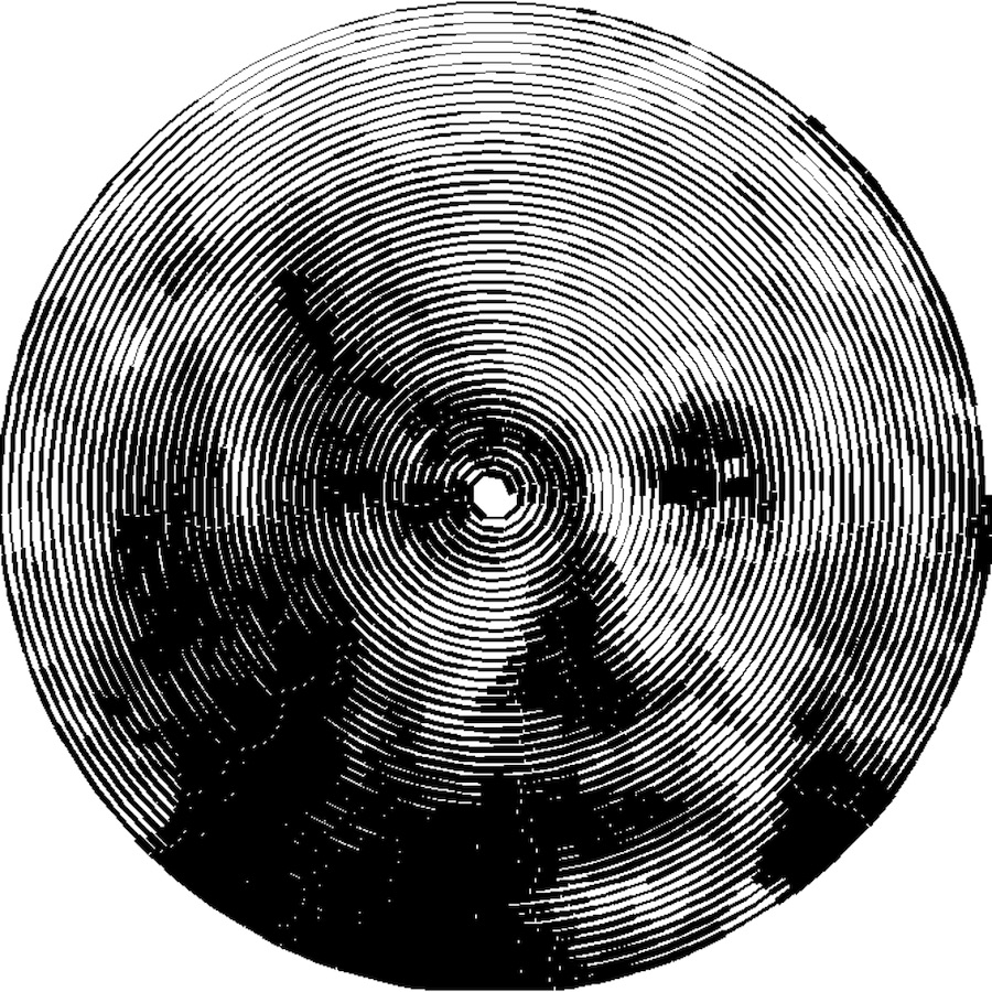
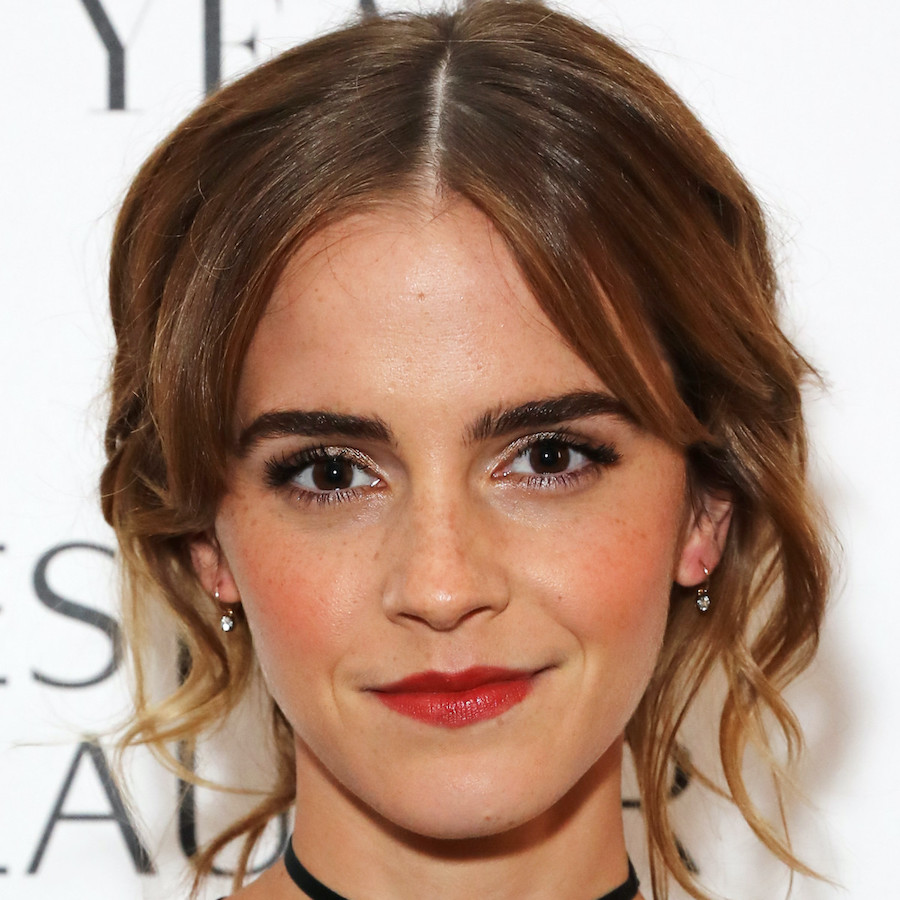
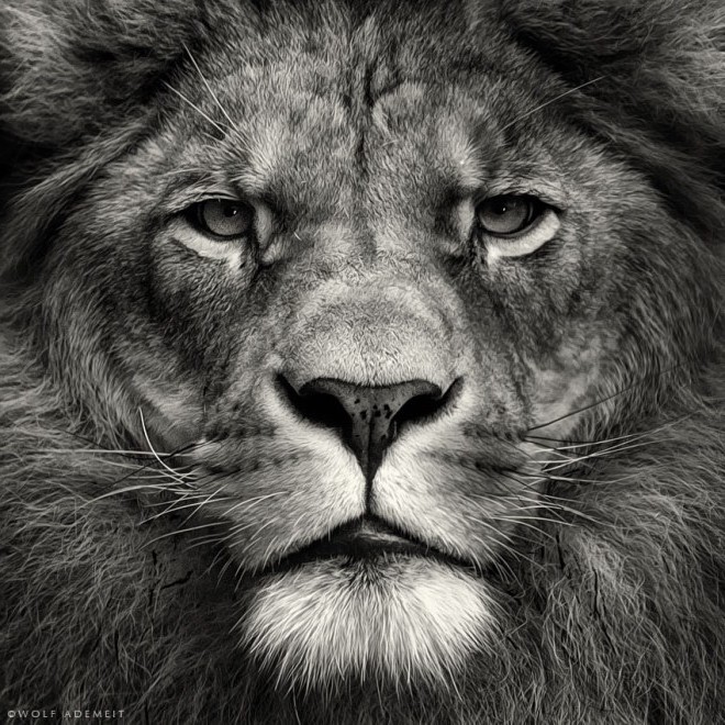
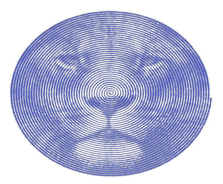
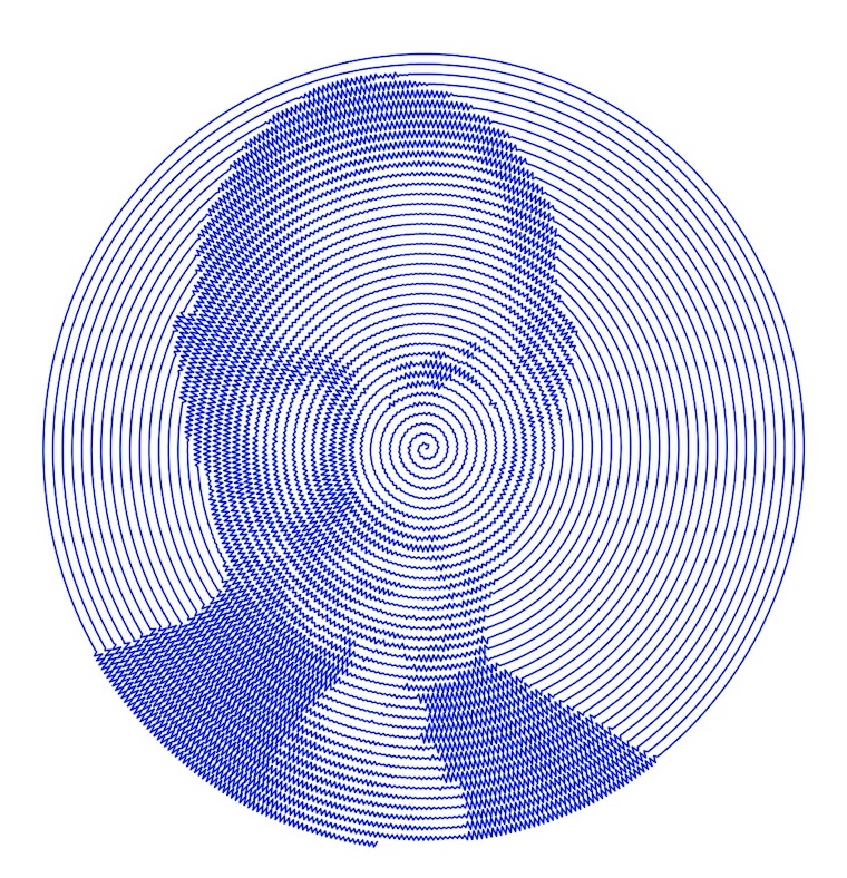
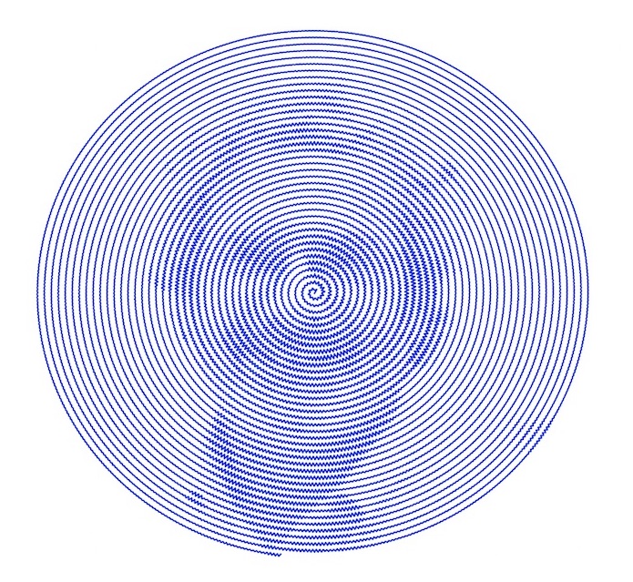
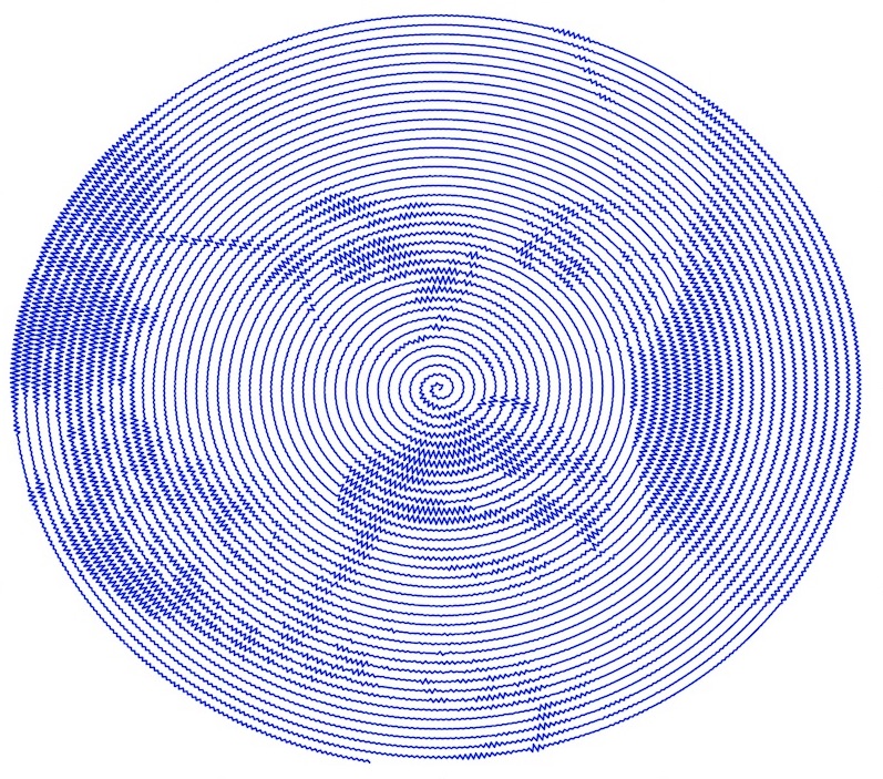
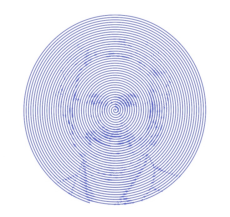
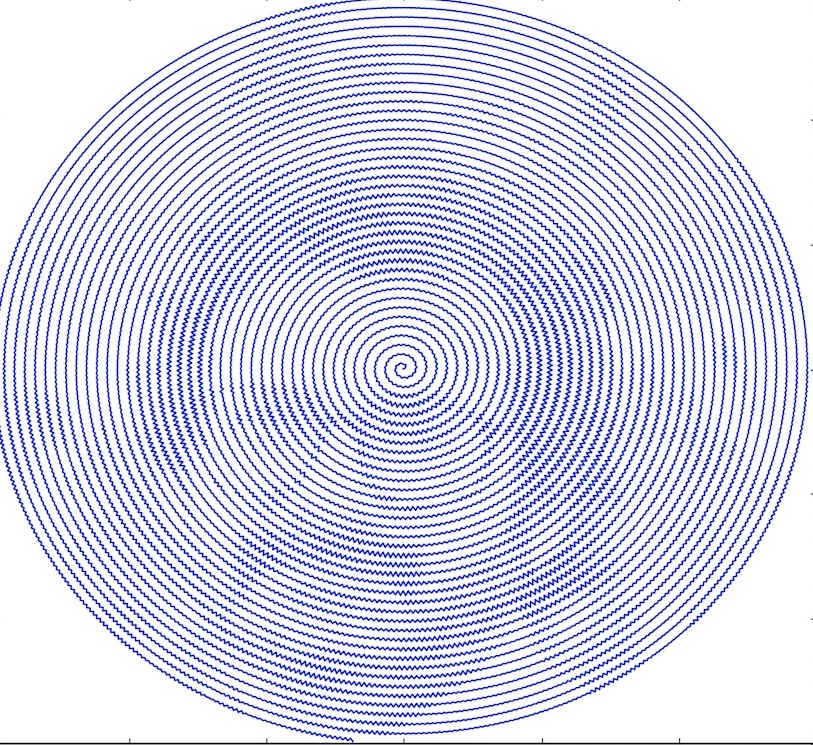
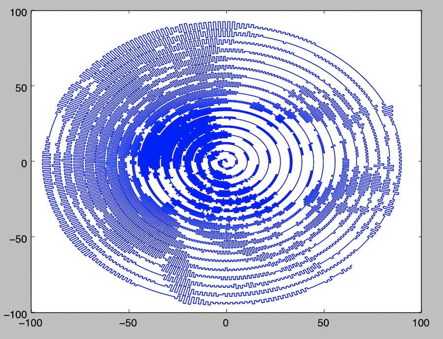
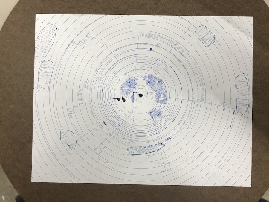
I'm going to try and make a machine that takes as input an image from the user and outputs artwork like this:


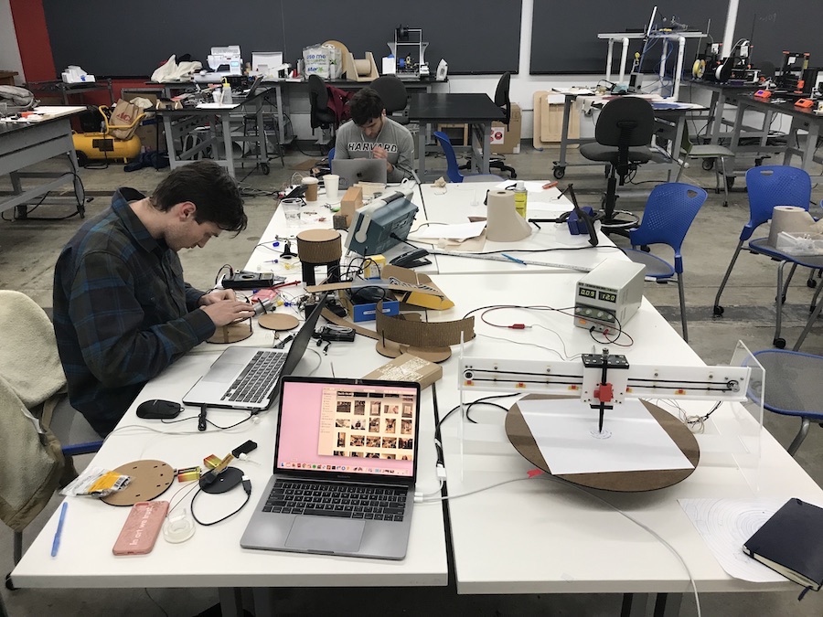
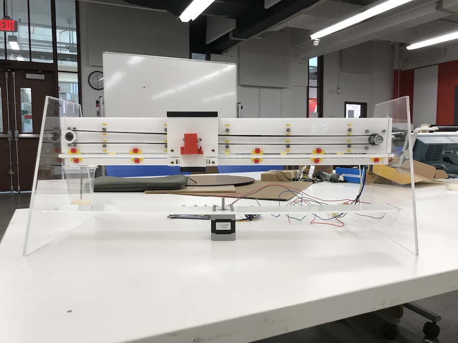
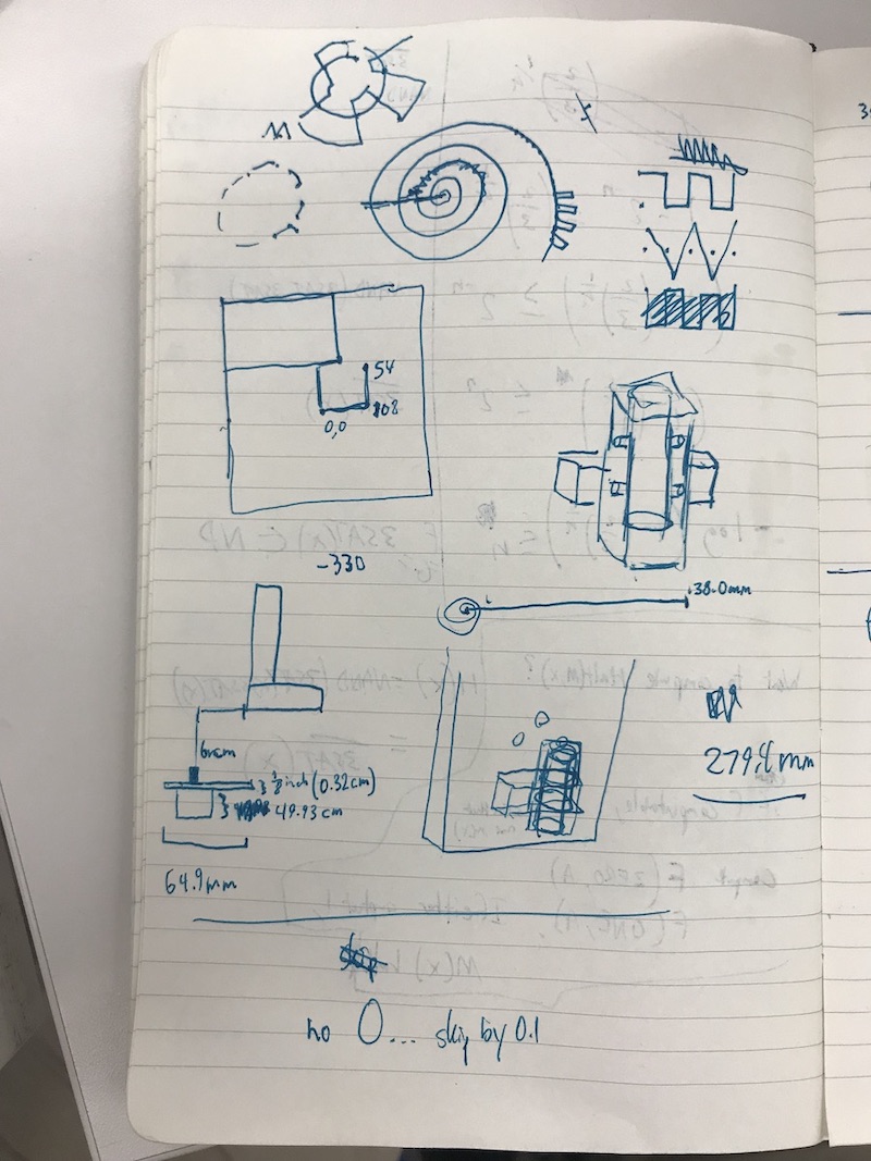
I started by sketching a design of how my final project would look. I would accomplish full motion on a plane through two degrees of freedom. I would use a motor and a gantry to control linear position and have a different motor control a spinning plate below to drive circular rotational motion. These two motions can be combined (with some polar coordinates mathematics magic) to produce any type of tool path. My first goal would be to get this machine to work to create these images. My stretch goal was to also design a printed circuit board with a few buttons on it that could serve as a joystick so a person can draw using the machine manually too.

I actually started with software first for this project. I used a few libraries for the script I wrote:
import numpy as np
import matplotlib.pyplot as plt
import math
from PIL import Image
I then opened an image, converted it to grayscale, calculated its dimensions, and created an array out of the image.
# Import Image and Convert to Grayscale
im = Image.open('image.jpg').convert('L')
im_radius = min(im.size) / 2
a = np.asarray(im)
I knew I would need to convert often between different coordinate systems, so I defined these to functions.
def polar_to_cart(r, theta):
return (r * math.cos(theta), r * math.sin(theta))
def origin_mid_to_origin_ul(x, y):
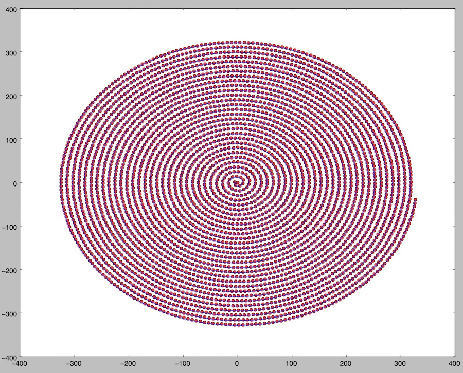
return x + im_radius, -1 * y + im_radiusI then generated points along an Archimidean spiral. At first, I generated each point by stepping from one to the next with a constant step size for θ. However, as you moved further out from the origin, points became further and further from each other. I wanted to generate points that were essentially equidistant from each other along the curve. I used an approximation I found here to calculate the right differential at each step for θ. Here's the code that generates equidistant points along an Archimedian Spiral:
# Generate Archimedean Spiral Points
LOOPS = 35
NUM_POINTS = 20000
b = im_radius / (2 * math.pi * LOOPS) # Given that radius of outermost point of spiral = b * 2 * pi * loops
max_t = math.floor((LOOPS ** 2) * b / 2) # max value for parameter t which generates points
step_size = max_t / NUM_POINTS
spiral_points_xy = []
spiral_points_polar = []
t = 0
while t < max_t:
	# Approximating equidistant points along the spiral
	# (https://stackoverflow.com/questions/44741045/placing-points-equidistantly-along-an-archimedean-spiral)
	theta = 2 * math.pi * math.sqrt(2 * t / b)
	r = b * theta
	x, y = polar_to_cart(r, theta)
	spiral_points_xy += [(x,y)]
	spiral_points_polar += [(r, theta)]
	t += step_size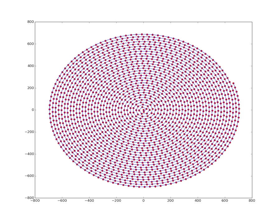
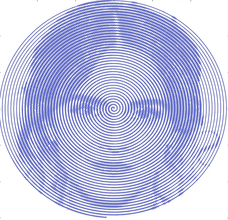
Finally, I needed a way to represent darkness and lightness from the input image. I decided that the best way to do this is to oscillate away from the Archimedian spiral proportionally to how dark the pixels in the image are below that part of the curve. Here is how I did that:
# For each point, perturb deviation from spiral to match color intensity of input image
max_deviation = im_radius / (2 * LOOPS)
MAX_COLOR = 255.0
for i in range(len(spiral_points_polar)):
direction = (-1) ** i
r, theta = spiral_points_polar[i]
spi_x, spi_y = polar_to_cart(r, theta)
im_x, im_y = origin_mid_to_origin_ul(spi_x, spi_y)
im_x, im_y = int(math.floor(im_x)), int(math.floor(im_y))
dev = max_deviation * direction * (1 - a[im_x][im_y] / MAX_COLOR)
r = r + dev
x, y = polar_to_cart(r, theta)
spiral_points_xy[i] = (x,y)
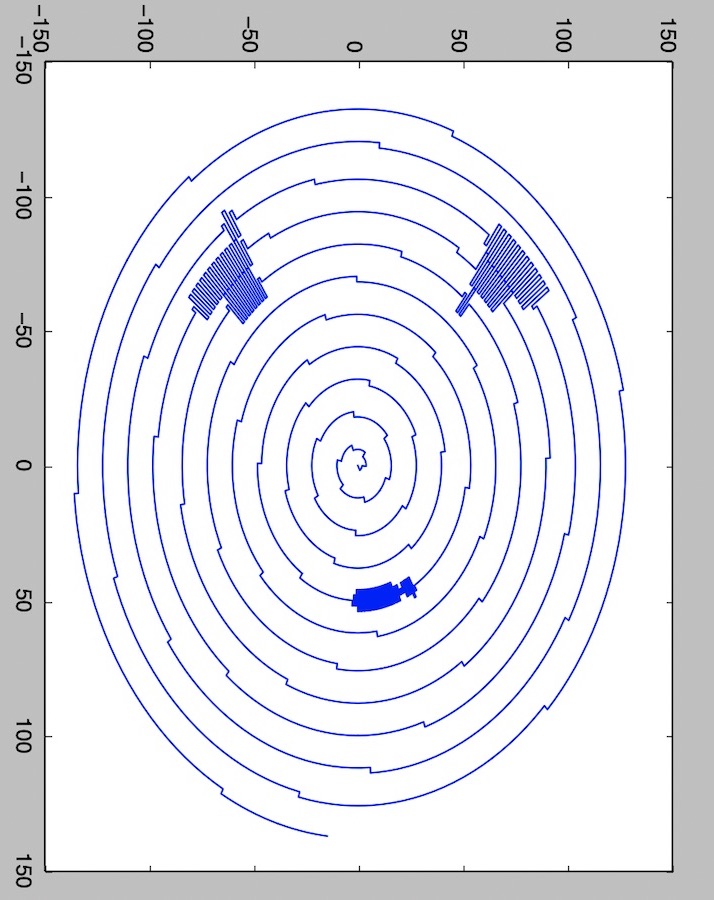
spiral_points_polar[i] = (r, theta)And then to display the generated spiral:
# Display spiral image
xs = [p[0] for p in spiral_points_xy]
ys = [p[1] for p in spiral_points_xy]
plt.plot(xs, ys)
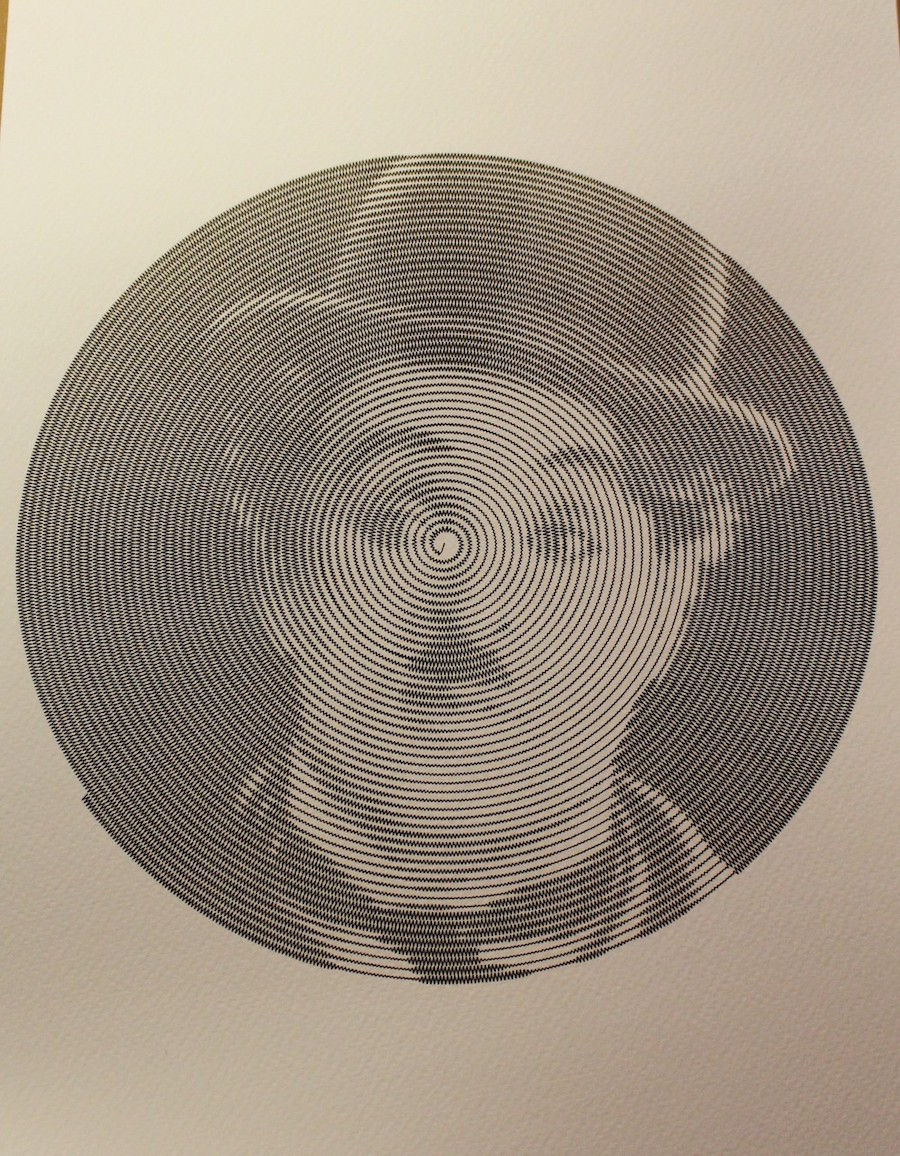
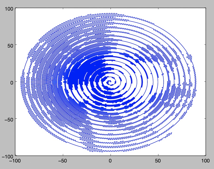
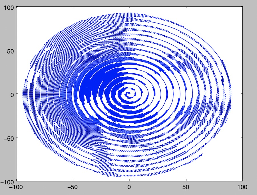
plt.show()Here are some results of my algorithm:


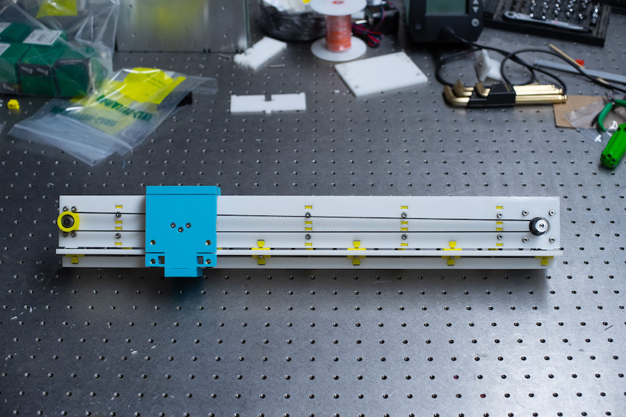
Next, I had to build the actual machine! I decided to use the gantry that Jake designed for Machine Week 2019.
Here are some assembly instructions that Jake also created which helped me greatly when building the piece.
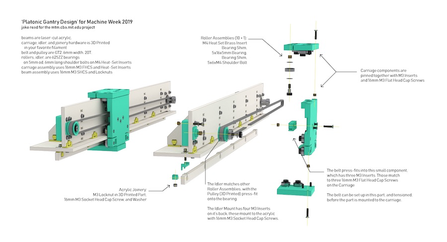
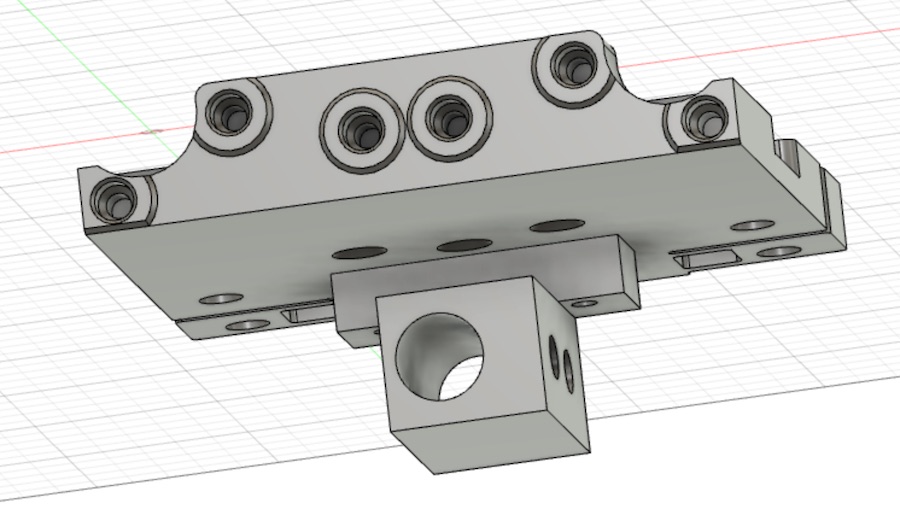
I did make two modifications to Jake's gantry though. First, I extended the width of it by 1cm so that there would be room on each end for a vertical stand to wedge into. Second, I redesigned the carriage to include a sharpie holder. Here is an STL file of the redesigned carriage. I bought a fine-tip sharpie and measured the diameter using calipers (10.5mm - 11mm), and then generated this holder for it to have room to slide into, yet be fastened with two screws on the side.
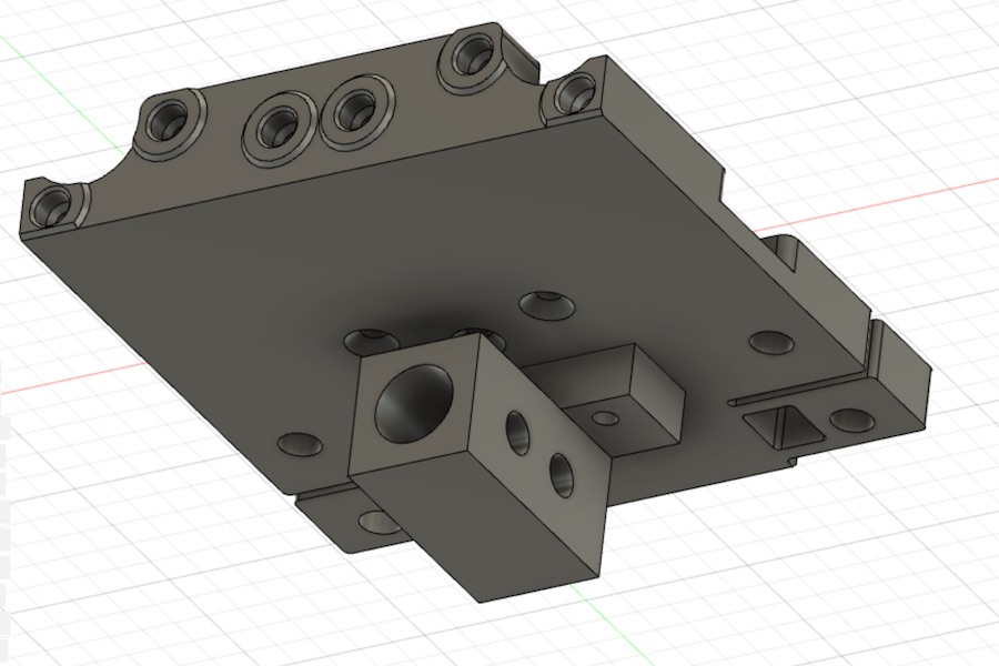
However, after doing some more measurements, I realized that if I wanted to get some heat-set brass inserts into those two holes on the side that I made, I would need to make the width on that side thicker. I could also thin out the other side. The holder doesn't need to be perfectly center anyway because I could later define the origin on the linear axis using a stepper motor. Here is the STL file of the pen holder
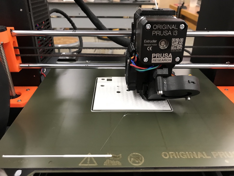
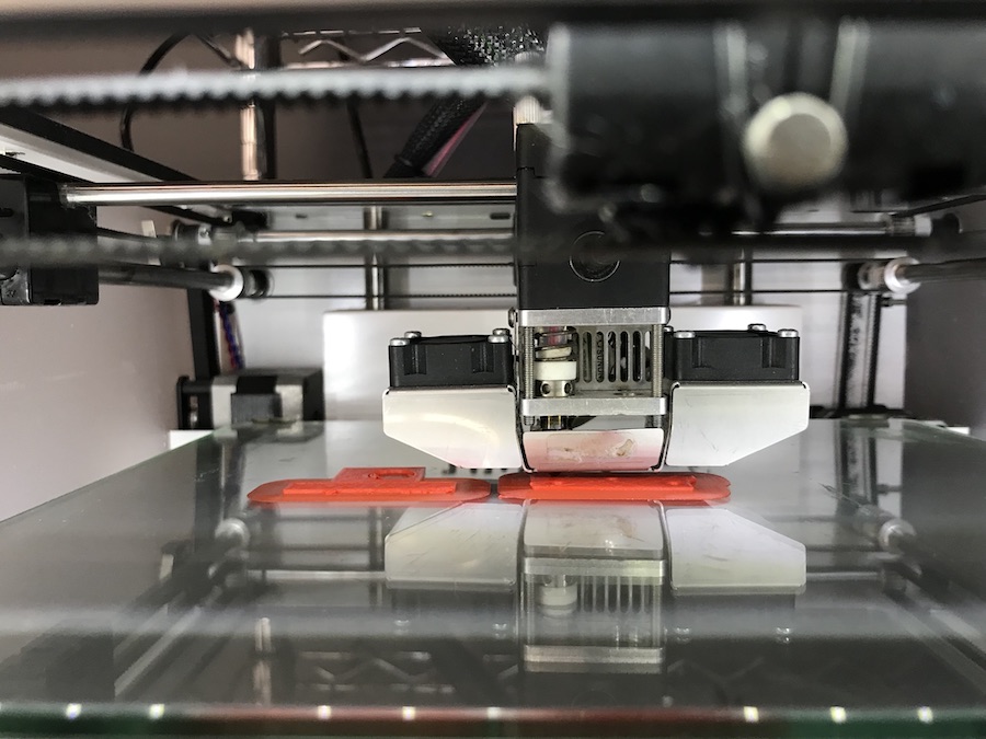
I then went ahead and 3D-printed all the pieces to make this carriage. I printed different pieces on different printers, taking advantage of what I had available. They ended up being a Prusa i3 MK3, Prusa i3 MK3S, and an Ultimaker 2+.
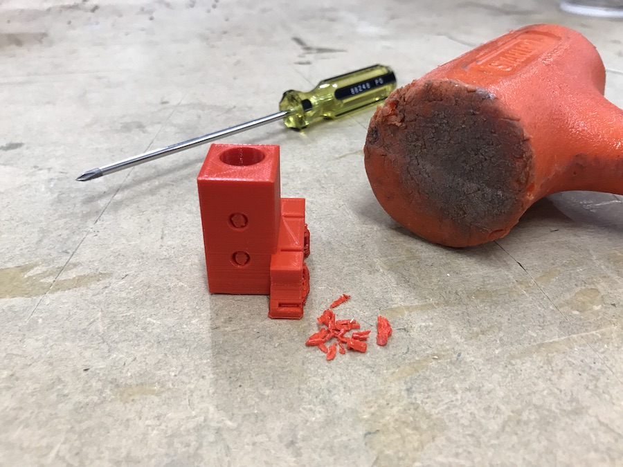
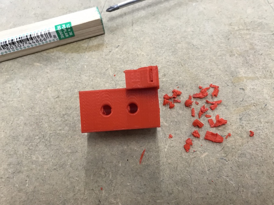
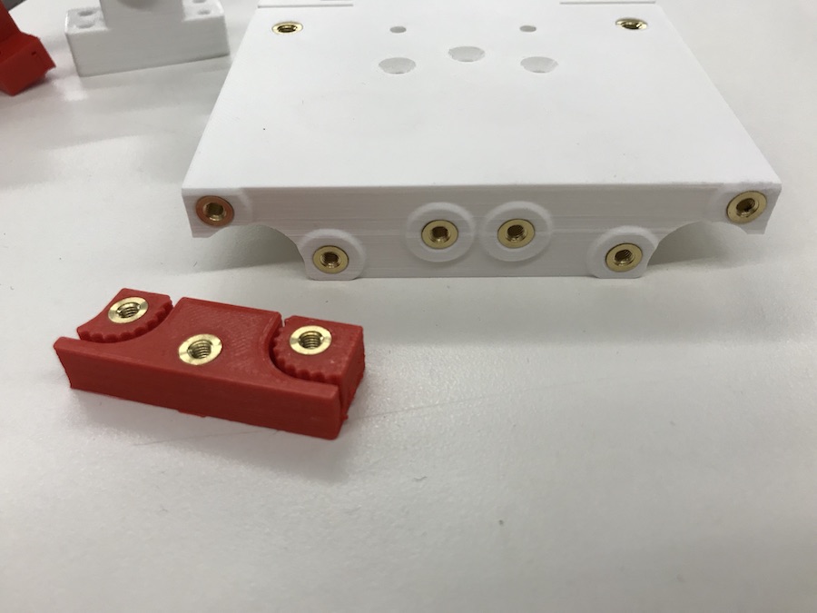
I also had some tricky support material to get rid of. Using a nail and a mallet, I carefully and slowly removed some hardened PLA from areas meant to be holes.
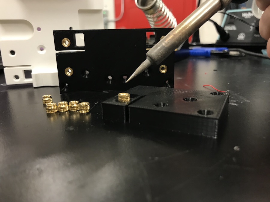
Then, I used a soldering iron to gently sink some heat-set brass inserts into my 3D-printed pieces. There were two different sized-inserts (M3 and M4), and I had to be careful not to mix them up. The feeling of the metal insert slowly sinking into the softened plastic was EXTREMELY SATISFYING.
Here are some fully finished pieces:
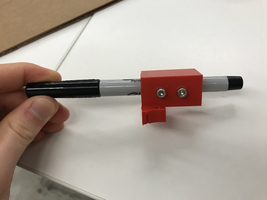
And here is the ultra-fine sharpie I bought fastened in the pen-holder nice and snug:
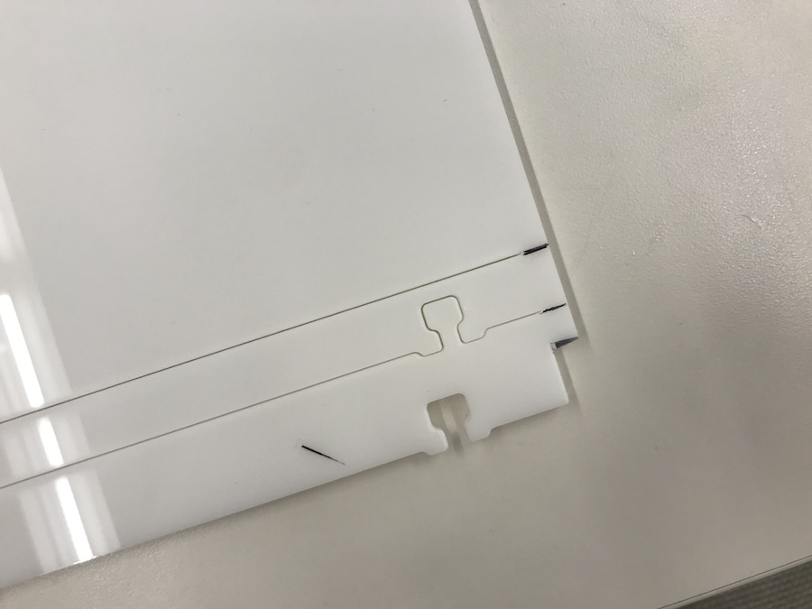
I then laser-cut the remaining large pieces for the gantry on 1/4" delrin. However, given the additional length I added to the design, the cut didn't fit within the bed of our Thunder Laser Cutter. I just had the machine cut as far as it can. Then I used a band saw to cut the last little stretch. On the more important pieces, I had Veronica help me cut the full pieces on a larger laser cutter in the Harvard basement.
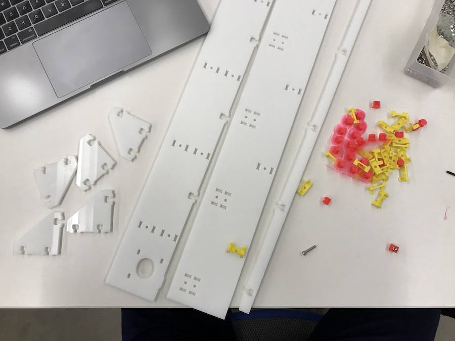
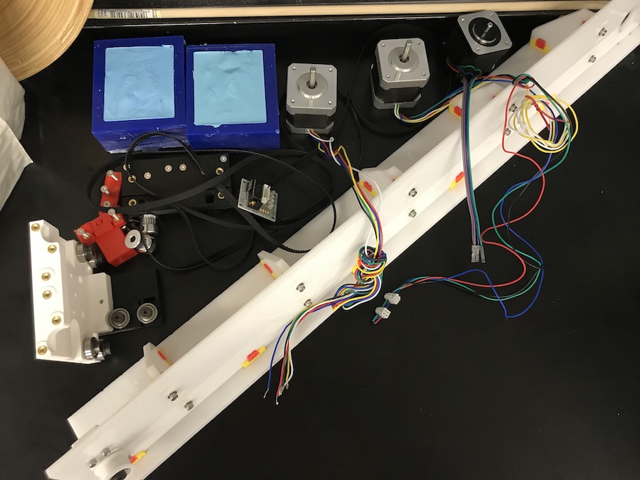
Here are all the cut pieces and some leftover 3D-printed joints from Jake's kit earlier in the semester.
This is the main arm of the gantry after assembling the acrylic along with some extra materials I got (stepper motors, belt, and pulley).
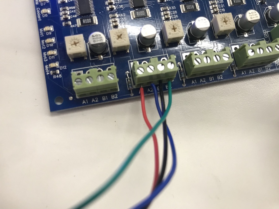
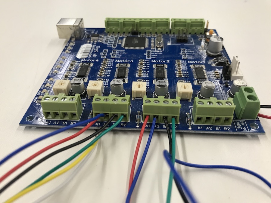
Before I screwed in any motor to my machine, I wanted to test them and make sure they worked. We had a TinyG board in our lab, which I would use for controlling the motors. The only problem was that the motors had 6 wires coming out of them and the TinyG had a connection made for 4 wires. There are 6 * 5 * 4 * 3 = 360 different wire combinations I could try to get the motor to work, but I knew that there had to be a way to actually figure out the correct wires. After a couple hours of learning about stepper motors on the internet, inspecting the data sheet for the motors I found (Unipolar Stepper Motor 12VDC .4A - Jameco Reliapro 238538) and watching the video below, I finally figured out which wires were important for driving the motor and in what order they should be inserted into the TinyG.
The correct order was Red, Blue, Black, Green.
I then designed a horizontal support for the stepper motor controlling rotation, laser cut that piece out on 1/8" delrin and then tried to screw the motor into that acrylic. Here is a DXF file of the horizontal ledge.
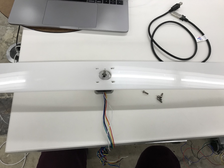
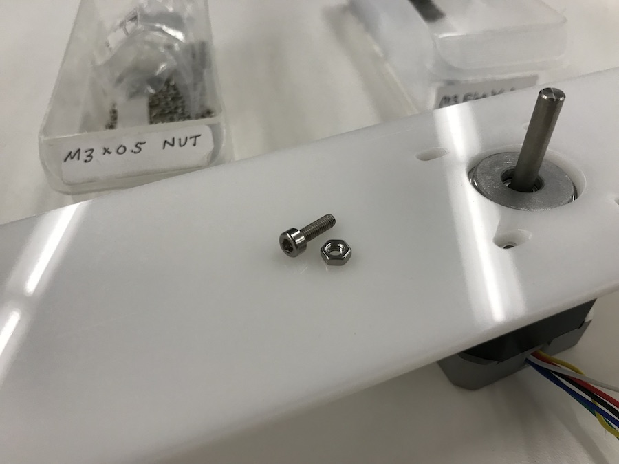
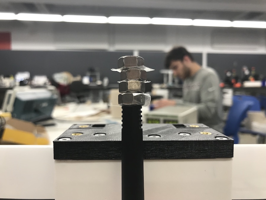
The 10mm screw wasn't long enough to secure the motor, so I found a decently thick nut that helped cover the remaining distance and keep things tight.
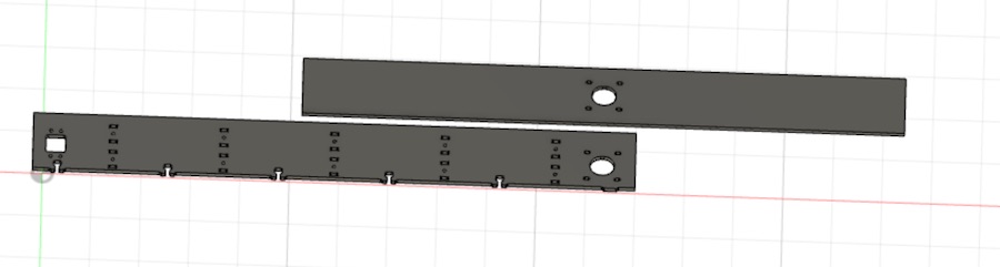
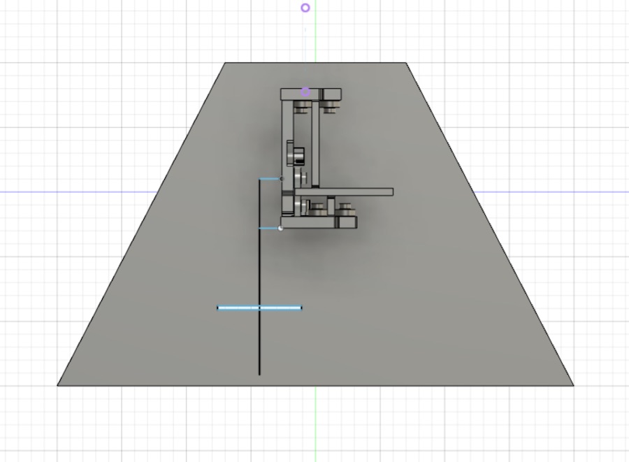
Next, I designed vertical stands for the machine. I calculated how tall the horizontal insert should be so that the motor would just be touching the ground. I also calculated how far out the center of the sharpie would be so that the motor controlling the rotation would be in alignment with the sharpie's point. And lastly, I made sure the distance between the horizontal bed and the pen tip would be able to be covered by the sharpie and pen holder. Here is a DXF file of the stand.
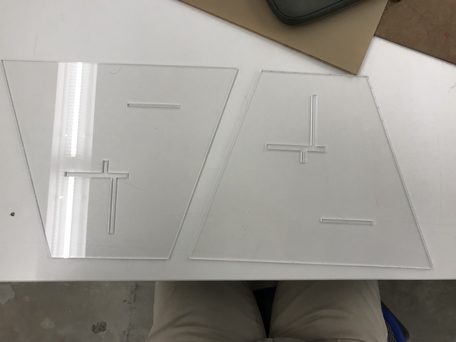
I cut out the vertical stands on 1/8" clear acrylic.
And then assembled it all together. I used a heat gun to soften the 3D printed part that the belt would sit in and used that to get the belt fixed.
I then created multiple sized washers using leftover delrin to test the diameter for a tight-fitting plate for the rotational motor.
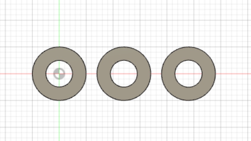
A 4.85mm diameter hole ended up being a perfect, snug fit for the motor's armature shaft.
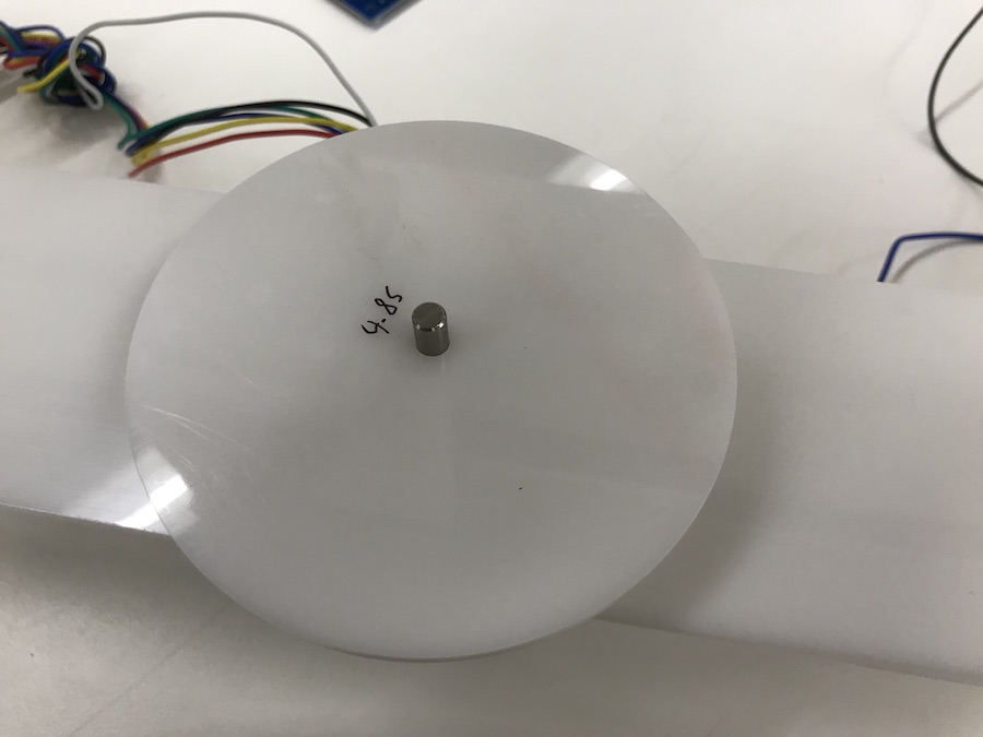
I then found the leftover plate from Harvard's machine week and repurposed it for my machine. Here is the finished physical structure for my machine. What a beauty!

I wired both stepper motors to the TinyG.
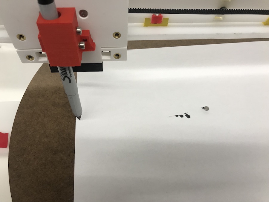
Then I attached my ultra-fine sharpie. However, I quickly noticed that whenever the sharpie sat idle for even a few seconds, the paper would immediately start to soak up the sharpie's ink and create these large splotches, completely undoing the benefits of having an ultra-fine sharpie.
I switched to a pen that I own that is not leaky, but writes with a light touch.
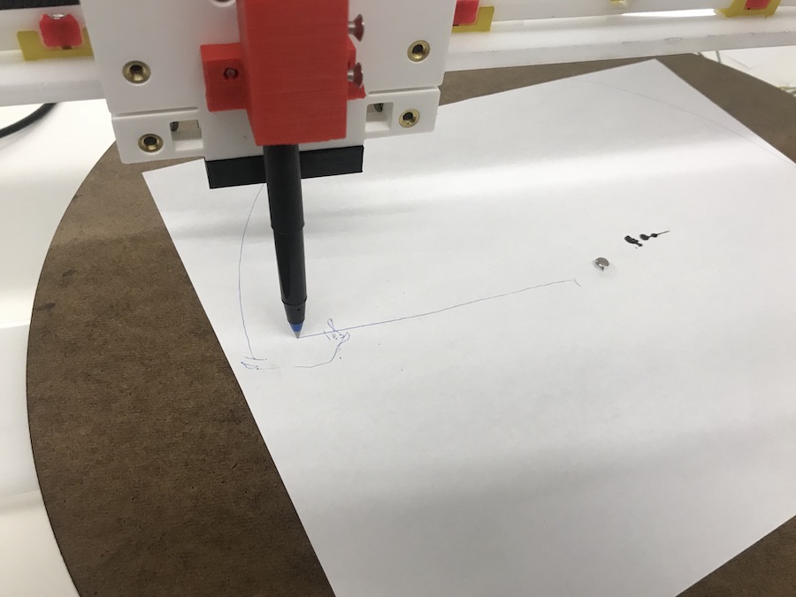
And then I started experimenting with G code commands to move the motors and control the pen. I used a program called CoolTerm to send data from my commputer to the TinyG. I followed the instructions here: synthetos/TinyG for finding the correct setting for CoolTerm to interface with the serial port correctly. I also powered the board and motors with an adjustable voltage power supply set to produce 12V.
One problem I noticed when I starting sending G code commands was that when I reversed rotational directions, the pen would lose its exact position because it wasn't fastened strongly enough in the direction perpindicular to the gantry. I could fix this by stuffing in some paper towel into the pen holder to surround the pen and keep it tight. However, when I did this, I created another problem. Previously, the force of gravity was keeping the pen in contact with the paper and bed below it. Once I added some paper towels, the pen got stuck in the z-direction and would lose contact with the paper below. NOT GOOD. I ditched the paper-towel idea and then just realized that for the drawings I was trying to produce, I would never need to reverse the rotational direction... so no problem after all! It's all good in the hood.
I decided to use G codes that executed relative movement to the motors because I was still doing a lot of testing. These take the form of G91 F900 Y5 Z10. G91 specifies relative movement for a motor. F900 sets the feed rate to 900. I experimented with different rates from F100, F200, ..., F1000, and found F900 to be satisfactory. Y and Z mean that we want to control the motor on the Y axis and Z axis (which is what the motors controlling the linear gantry and the plate rotation were hooked to on the TinyG), and 10 and 5 mean how many units each motor should turn.
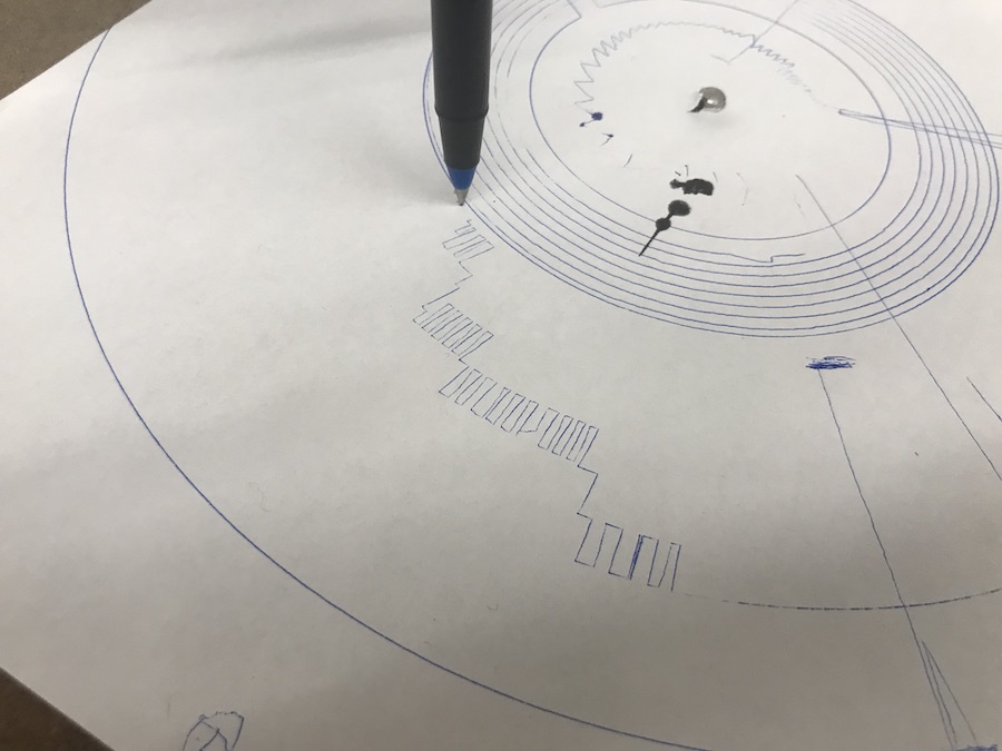
One problem as I was testing was that the types of oscillations I wanted to create at the scale I wanted them to work were not coming out well. This is because at the resolution I was interested in, the motors were taking very small steps at slightly different times, leading to jiggles and not creating perfectly straight motions.
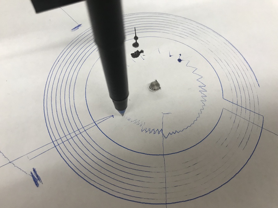
However, I discovered a new way of moving the motors and pen to create very straight and reliable form of oscillation with variable thickness.
I did some calculations and rewrote my code to take advantage of this type of motion I was able to perform. I also added a section in my code to write G code corresponding to this new motion to a .txt file that I could eventaully send over to my motors through the serial port of the TinyG.
One other change I made was adding a parameter to control how large of a sampling window you should use for figuring out the darkness of a region (just the pixel below the curve vs surrounding pixels too. From left to right, you can see the same image with a single pixel sampled, a 3x3 region of pixels sampled, and a 7x7 region of pixels sampled. The increased window simply smooths out the surve.
I also performed many tests to figure out the minimum step size I could take rotationally and the minimum linear step size I can take as well. I then rewrote my code to factor in these two properties as well as the size of the physical canvas. I also allowed a user to set the resolution of each oscillation (how many different sized oscillations are possible). Lastly, to work with this new oscillation technique, I ditched the equidistant points and went back to points that were equiangular. My final code can be found here: im-to-spi2.py
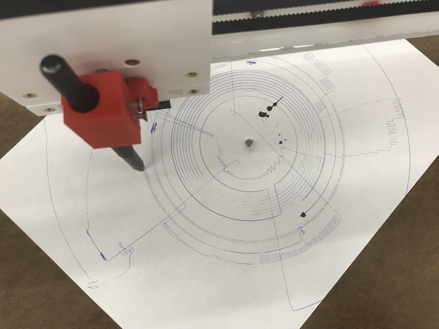
I also had to deal with new problems that came up when calibrating. After lots of trials, there did end up being some slipping on the paper. I added some weights to the top of my pen to keep it touching the bed.
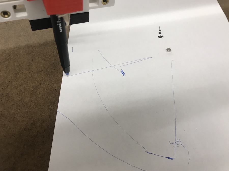
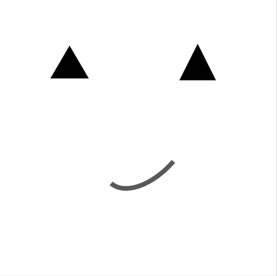
Also, when the machine didn't need to oscillate because of white space and just rotated to the next position for oscillation, the amount of rotation it moved in this faster motion did not actually cover the same distance as the amount programmed. I discovered this when attempting to draw a simple smiley face.
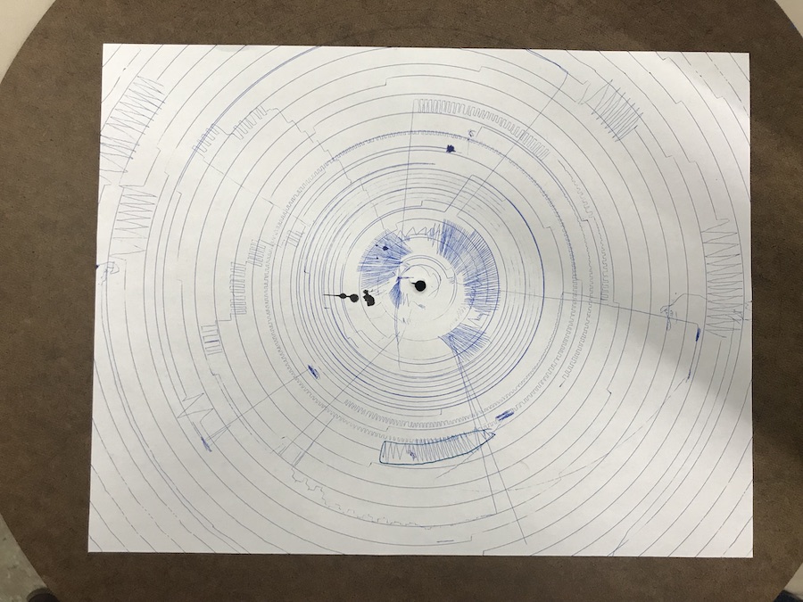
The pieces just completely became misaligned! So, I rewrote the code to add the smallest amount of forced oscillation to the spiral whenever it didn't need to oscillate. That way the rotational movement would still be in sync with the code. However, because of the resolution needed to draw good images, each spiral produce on the order of 10,000-20,000 points, or about 10^5 G code commands. This would mean that one drawing would take about 1-2 hours to produce, and if there was some small error, it would still propogate throughout the entire drawing and be very hard to correct.
At this point, at 3am the night before our presentation, I became way less confident that I could calibrate the machine in the way I needed to produce the types of high-resolution drawings I wanted. I called it a day, a night, and a semester.