My goal for this week is to figure out how to set up the ESP32 and get an LED blinking.
For my final project, I want to have an indicator LED that switches on when the audio is being saved and that blinks when the device is in networking mode and is transmitting
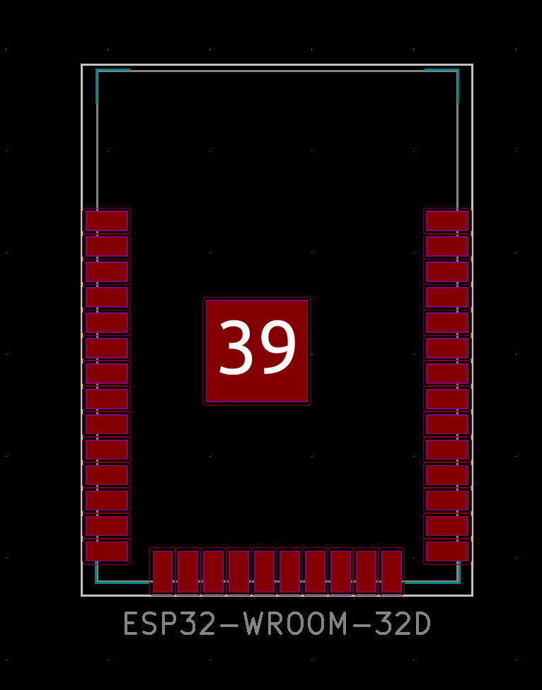
The ESP32 has 32 pins, 2 cores(!) and Bluetooth and WiFi capabilities. The ATTiny has lots of fun stuff built in, but the ESP32 is certainly more powerful — and to handle audio processing (which requires sampling and saving a signal at 44k hertz) it is the right choice.
The first thing to do was to find the footprint for the ESP32 — luckily, because I am using KiCad it was included in the Digikey Library.
I had previously writen a function that blinks an LED when a button is pressed which works with the ATTiny. I think the code will need to be rewritten in order to work with the ESP32.
void blink(int num) {
   static int duration = 300;
   for (int i = 0; i < num; i++) {
      set(led_port, led_pin);
      _delay_ms(duration/2);
      clear(led_port, led_pin);
      _delay_ms(duration/2);
   }
}
while (1) {
      if((PINB & button_pin) == 0) {

         //debounce
         _delay_ms(100);


         count++;
         blink(1);

         //check if long press
         int long_press = pin_test(PINB, button_pin);

         if (long_press == 0) {
            set(led_port, led_pin);
         }
         //swallow button press if it is still held
         while (0 == pin_test(PINB,button_pin));

         if (long_press == 0) {

            //long press resets counter
            clear(led_port, led_pin);
            _delay_ms(250);

            blink(count-1);
            count = 0;

         }
}
To make the board I just modified Neil's design, adding an LED and PCB.
I want to do a bit of prototyping to check that my circuit board is wired up properly. Using the Arduino libraries lets me write much less boilerplate.
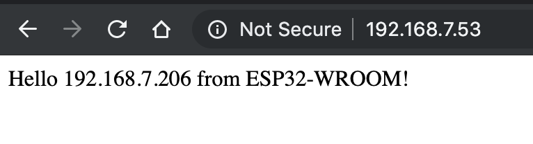
Getting started was quite easy. I had already set up the ESP board profile in the Arduino IDE. I ran Niel's ESP32 web server example and it worked on the first try.
Just open the file with the Arduino IDE. (You will be prompted to create a folder which you should do).
Verify & Compile — ⌘R
Upload — ⌘U
You will be asked to select the serial port.
I played around a little bit with the button and LED to see if everything was connected properly.
Here is the Arduino code that I used:
const uint8_t ledPin = 16;
const uint8_t buttonPin = 17;

volatile byte state = HIGH;

void IRAM_ATTR isr()
{
 state != state;
 Serial.printf(".");
}

void setup() {
  pinMode (ledPin, OUTPUT);
  pinMode(buttonPin, INPUT_PULLUP);
  attachInterrupt(buttonPin, isr, FALLING);


  Serial.begin(115200);
  printf("\nConnecting ");
  WiFi.begin(ssid,password);
  while (WiFi.status() != WL_CONNECTED) {
    delay(100);
    printf(".");
    }
  printf("\nConnected with address %s\n",WiFi.localIP().toString().c_str());
  server.begin();
  }

void loop() {
    digitalWrite(ledPin, state);
}