⚡ Maya Murad

Final Project
Installation X

                                                   The Challenge

Final project should incorporate 2D and 3D design, additive and subtractive fabrication processes, electronics design and production, embedded microcontroller interfacing and programming, system integration and packaging

Inspiration

More inspiration: generative art & interactive light installations

                                                   The Inspiration

I had been exploring the concept of generative art over the summer. Generative art is a type of art that as a whole or in part has been created with the use of an autonomous system.

I started digging around and became more interested in making tangible generative sculptures that would adapt to their envirobment.

                                             First Concept Iteration

I am planning on making a portable interactive sculpture / lights display that would react to its environment.

The sculpture itself would composed of a grid of small pins that can move up and down. Each pin would have its own RGB light.

The scultpture itself would modify in shape and light intensity based on environmental data (temperature / humidity) as well as user interaction (proxmitiy data).

I will be iteratively developing this piece, starting with the simplest design possible and then seeing how we can upgrade the installation to more complex interactions.

CAD modeling of simple version of installation (Fusion 360)

                                                   First Challenges

After deciding on the first concept, I faced a few challenges:
  • The cost of a small linear actuator ~$15 and accoding to my design I would require ~15 of them
  • Controlling a large grid of linear actuators is challenging and I am relatively new to electronics

                         Fix #1: Cheap Linear Actuators

By designing a simple rack and pinion model and 3D printing it, a simple servo motor which costs ~$3 can be turned in to a linear actuator.

Rack & Pinion CAD model

                         Fix #2: Reducing the number of motors required

I needed to achieve a tradeoff between having interesting and complex movement in the installation while having a small number of linar actuators. The solution for that is to have 3-5 linear actuators moving a semi-rigid & flexible surface.
I started exploring living hinges, first on acrylic, which failed fast! then on wood, which worked much betted. I ams also looking into parametric folds.

Laser-cut living hinges from most to least flexible

Example of parametric folds I will be experimenting with during WildCard Week

                                             Second Concept Iteration

After looking into the most challenging parts of the project and doing some quick prototyping, it became apparent that the initial design needs to be modified.

Simple explanation of how the installation will work:
  • Installation inputs: switches to turn the machine on and a color sensor.
  • Installation outputs: data read by the color sensor will control both the movement of linear actuators and the color displayed on an RBG LED strip which will be stuck underneath the flexible top.
  • Microcontroller: I chose to use the ATtiny3216, which is similar to the ATtiny1614 and has 20 pins.
The aim is for each electronics component to be on a seperate breakout board.

Main board connected to 5 servos, LED strip and breakout power and sensor board

Power source breakout board (connected to 9V battery)

Breakout board with color detection sensor

Casing to be laser cut on 1/8 inch acrylic sheets

Finished casing

First attempt at integrating the electronics (which didn't work)

                                             Third Concept Iteration

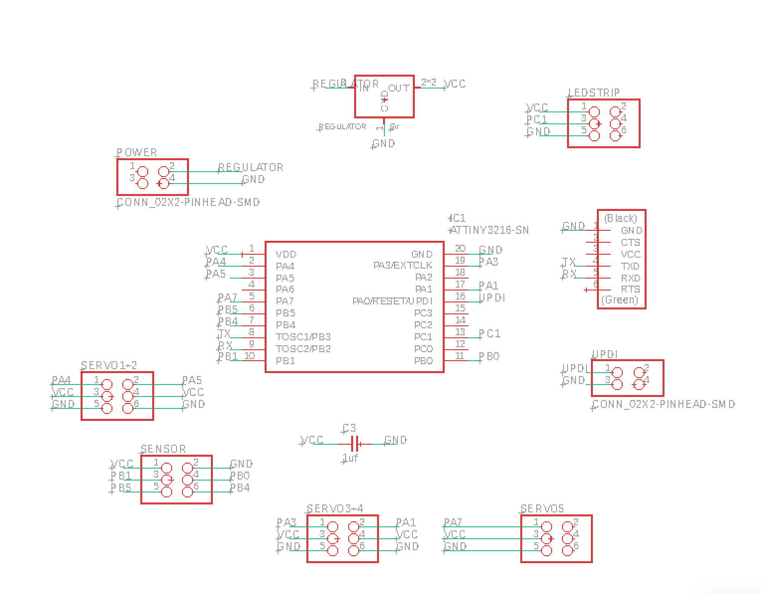
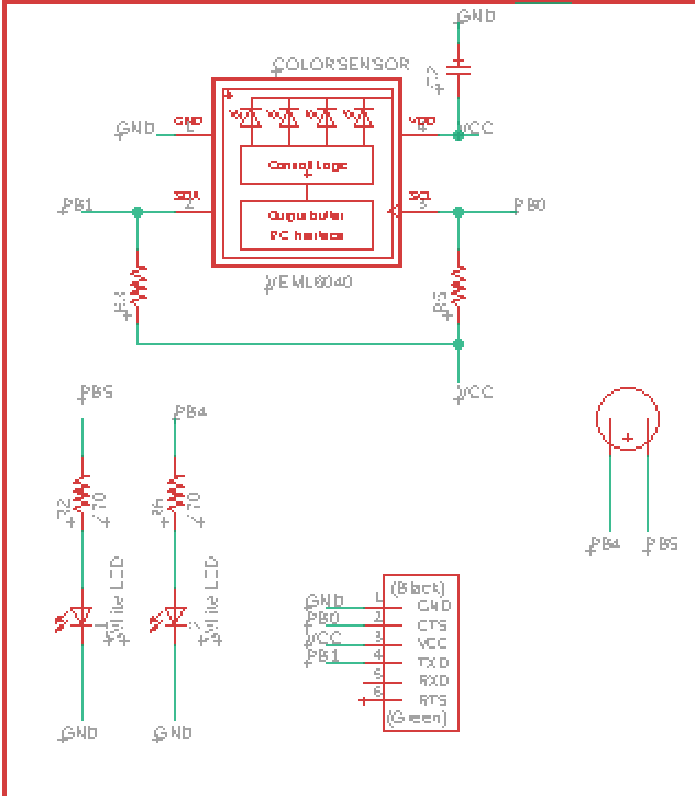
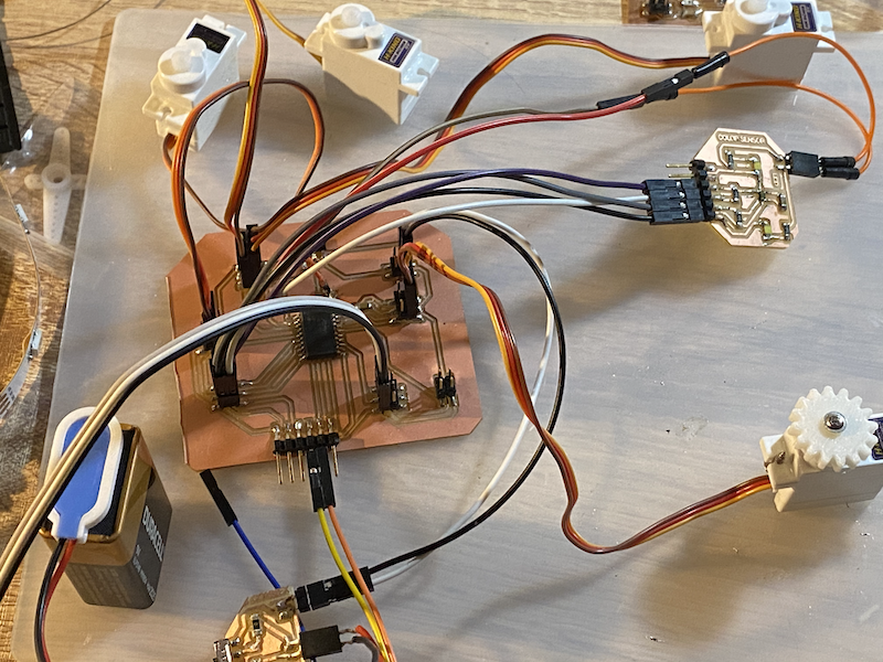
I unfortunately could not make the the full circuit work with the VEML6040 RGBW color sensor mainly due to the fact it operates at 3.3V whereas the servo motors require 5V.
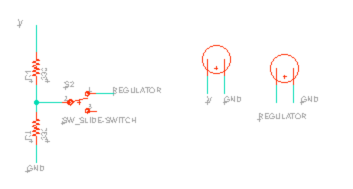
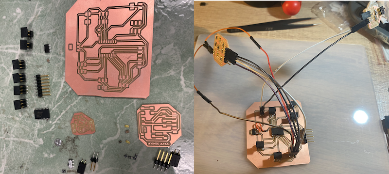
I attempted to create a seperate breakout with a 1amp 3.3V regulator, however the rest of the board did not work. I had to unfortunately ditch the color sensor at the last minute and replaces it with an HC-SR04 ultrasonic sensor which I had readily available. 
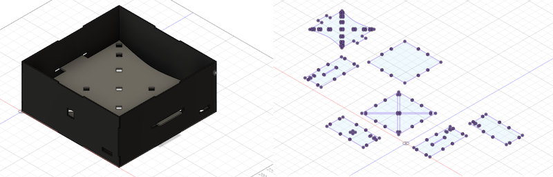
I pivoted the project to make the servo motors and LED strip react to distance from nearby objects.

Moreover, I had to ditch the battery breakout board as the 9V battery could only power 2 servos + LED strip.

Fortunately, I was able to reprogram my main board to work after the pivot.

                                           Working with HC-SRO4 ultrasonic sensor

In the new setup, the LED stip brightness and angle of movement of servo motors is inversely proportional to the ultrasonic sensor readings.
One issue I faced, as demonstrated in the video, is that I'm getting 'fuzzy' readings (0 and 1149), I tried severak ways to reduce the noise and eventually wrote a script to drop these 2 readings.

HC-SRO4 ultrasonic sensor from Maya Mourad on Vimeo.

Code used to program the ATtiny3216 board

Project summary can be found here