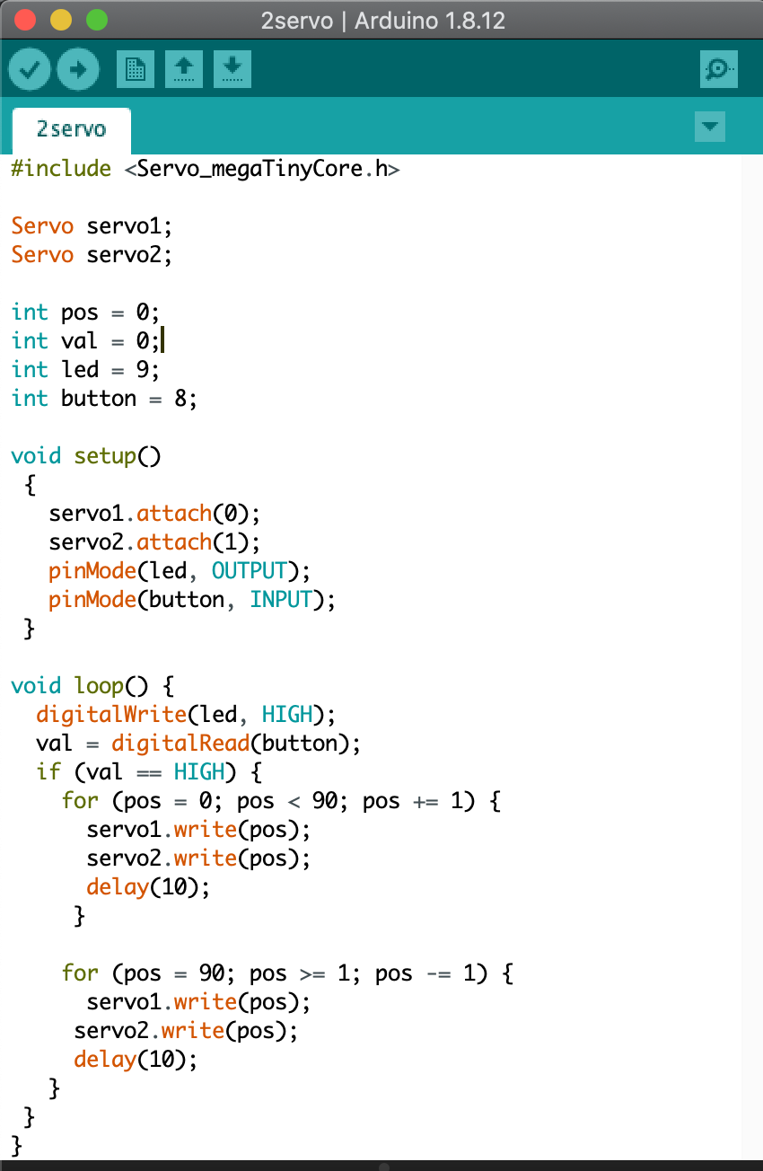
Add an output device to a microcontroller board you've designed,
and program it to do something. [Individual]
Measure the power consumption of an output device. [Group]
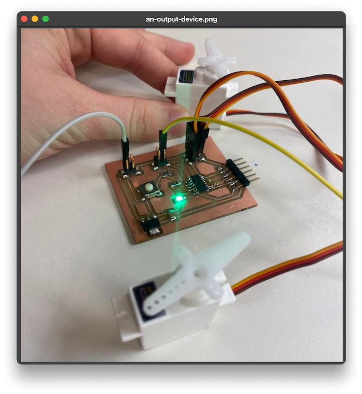
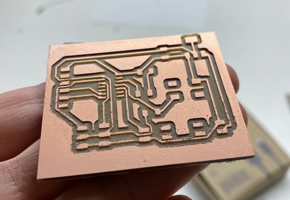
The motivation for this week was to prototype a smaller version of the output device required for my final project. I wanted to create a board to control 2 servo motors using an ATtiny1614 microcontroller which is powered by 9V a battery pack.
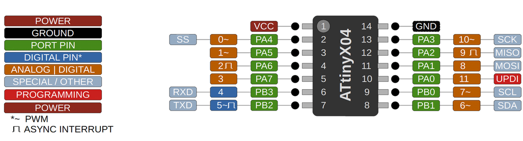
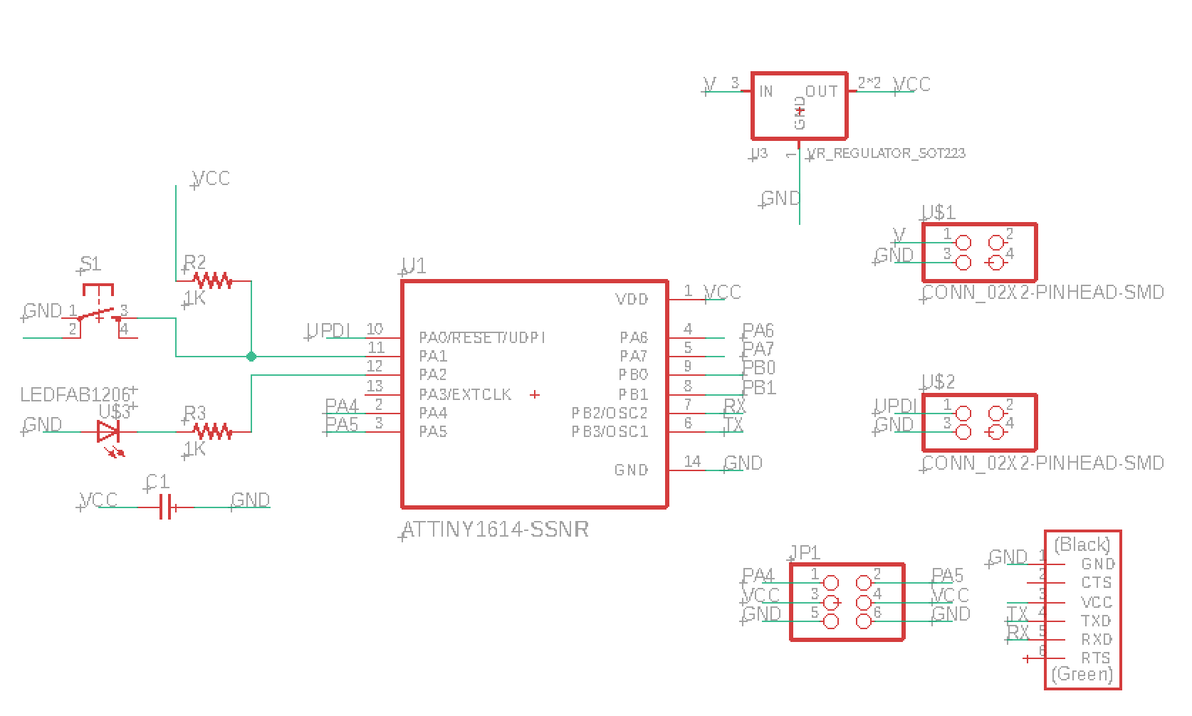
Based on the ATtiny1614 pinout, each of the two 5V servo motors should be connected to an anlog pin on the microcontroller.
A 5V regulator is added to control the voltage flow of the 9V battery pack. The regulator voltage should always be lower than the battery voltage.
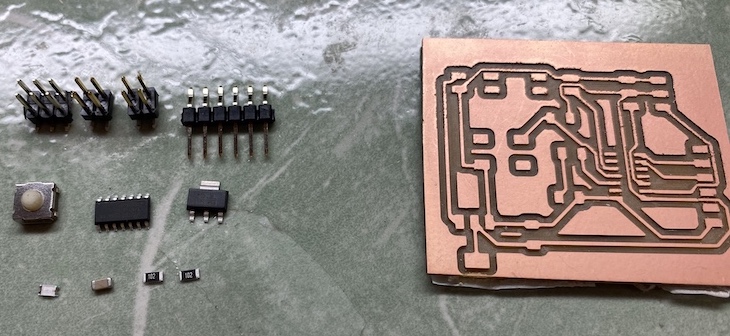
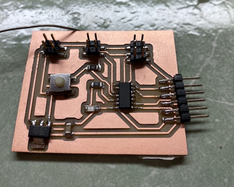
I also connected a LED that goes on whenever there is power going through the board.
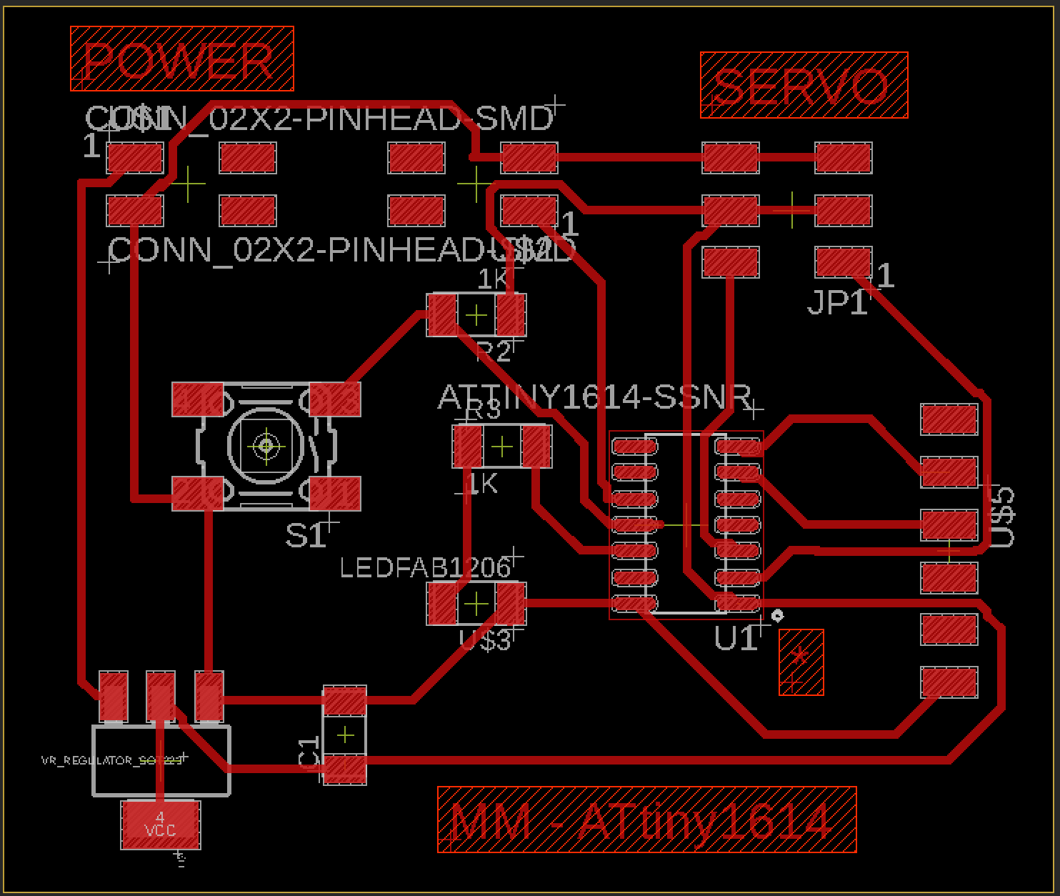
One mistake I made in my board is that I place the capacitor too far away from the microcontroller. Additionally I used a 3.3V regulator by mistake instead of a 5V one. There was enough current circulating through the board to activate the LED and the servos.