For week 3, we step out of the 2-dimensional world of laser/vinyl cutting, and get the opportunity to do some 3D printing and scanning.
This week I will design and print a venturi pump, which is a pneumatic component that provides a convenient means of using a compressed air source to pull a vacuum, by means of the venturi effect. For context, the venturi effect is used in carburetors to vacuum up liquid fuel and mix it with air, in an air brush it’s used to siphon up paint and spray it out of a reservoir, and it’s also a convenient way to pull a vacuum for industrial applications, like a robotic gripper. Venturis have no moving parts, and so are largely maintenance free, but at the cost of being incredibly loud and inefficient. The video below shows a version of the venturi I designed and printed vacuuming up fruit punch (the purple liquid) and ejecting it into a bottle. The video was shot in slow motion on my phone’s camera, and in real time the full ~50mL is vacuumed up in about 3 seconds.
Some objects lend themselves particularly well to 3D printing, usually due to the need for customizability (invisalign dental molds are actually the largest single volume mass application for 3D printing). Because 3D printing is very geometry tolerant, it’s also useful for manufacturing a part with otherwise prohibitively difficult features to machine/mold. Like lots of fluid-handling parts, venturis have tricky internal features that involve routing fluids with smooth radiused internal transitions, and so they fall into the latter category. Commercial venturi pumps are usually manufactured out of multiple pieces of machined aluminum, and can get very pricey despite externally looking very simple.
This week I plan to design and print some venturi pumps, and then hopefully put one in the CT scanner to explore the geometric parameters that allow for the tradeoff between peak vacuum and max flow rate (some are optimized to pull very high vacuum at low flow rate, and others vice versa).
I took a naïve attempt designing something in Solidworks, and then exported an STL to print on a Form3. I chose the Form3 and SLA, because it can produce very smooth surface finishes, and this particular geometry which grows continuously out of the build platform could be printed with minimal support material. Below is a model giving you a rough idea of how fluid will move through the pump, and hopefully gives you an idea of why this part would be difficult to make subtractively.
Since customizability is another strength of 3D printing, I decided to do a parameter sweep on the distance shown in the screenshot below, which I was speculating might effect the tradeoff between max flow rate and peak vacuum. I printed four versions and incremented my dimension by 2mm each time. My thinking here is that the size of the opening (largest at 7mm and smallest at 1mm) will dictate the “back-drivability” of the pump. For example, fans designed to push a large volume of air will have several large blades with aggressive angles of attack, and also large gaps between those blades. Fans designed for high pressure (pushing air through a porous medium) are often centrifugal, and have comparatively smaller gaps between blades. This intuition could be totally wrong, but I am writing in real time so hopefully will pull some meaningful data out of this parameter sweep by actually pulling vacuum on a closed chamber and measuring time to hit steady state.
The selection of fittings in the lab wasn’t quite as diverse as I was hoping, so in the end I only actually pulled vacuum with two of the pumps (the 1mm and 5mm). I epoxied some nylon fittings onto my prints, and later epoxied some more fittings to those to get to 3/8” pneumatic tubing. Disclaimer that none of the CBA regulators could be adjusted past 65psi, and were inconveniently mounted by the ceiling, so I quickly gave up on adjusting for optimized pressure. I did find that optimizing supply pressure is probably critical, as one of my printed venturis actually stopped pulling vacuum past 45psi, and just ejected air (maybe because we enter a turbulent regime?). The fancy venturi I scanned and used below is also rated for 80psi specifically.
In the end both of my designs pulled around 5” Hg, and the OTS venturi pulled slightly less (it specs 28” Hg on the datasheet so I suspect this was a problem with my setup). You can see my setup above did leave a lot to be desired. I wanted to use a bell jar as a vacuum chamber, but settled on the plastic bottle with fittings, to get an idea of time to achieve max vacuum (with time and volume I could estimate flow rate). All of the pumps I tested immediately shot to ~5” Hg and stayed there. Once I have higher supply pressure I will setup another test rig with my own regulator and re-run these tests. For now I would say there’s not much to infer from the data unfortunately.
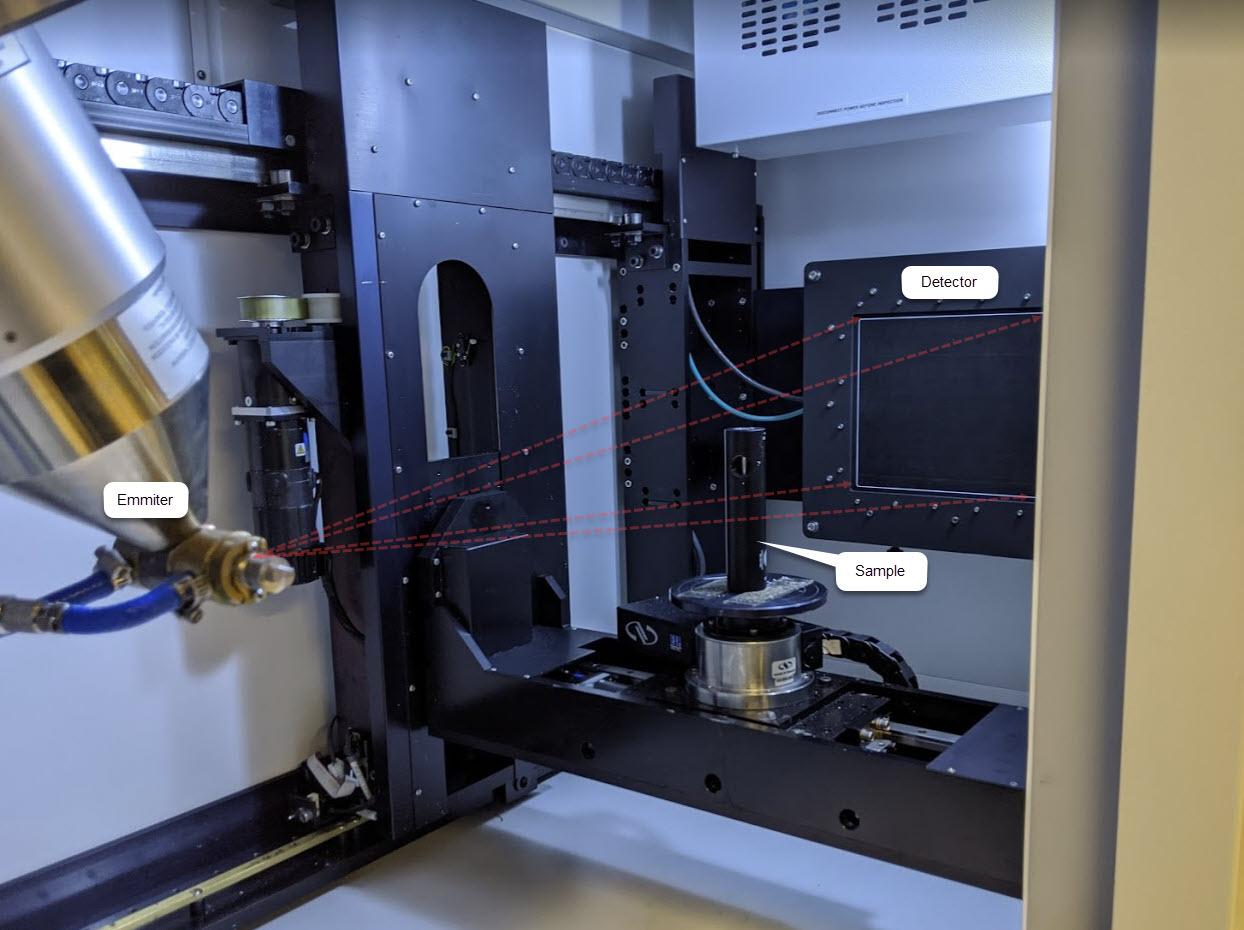
The CT scanner is actually the machine that I am most excited about getting access to through the CBA, so rather than going the traditional scanning method here, I asked Erik for another favor and got to spend a couple of hours learning the workflow. Below is a shot of the inside of the CT scanner. For a more detailed writeup of how it works jump to the section below.
To my surprise, I wasn’t terribly far off with my venturi design. Notably my expansion tube was way too aggressive, and the ratios of some of my diameters were definitely off. The venturi I was able to find and scan was designed to operate at 80 PSI, and pull up to 28” HG. Vacuum optimized venturis are capable of pulling up to 29.5” Hg, where a perfect vacuum is 29.92” Hg. I was surprised by how the initial “straw” coming from air-in actually immediately opens up like an expansion tube, and then the expansion tube itself then immediately constricts before opening back up again! There’s a lot of hardcore CFD that goes into optimizing these pumps, so I don’t know if this design is based on analytical models, or just crunching through parameter space in simulation.
Below is the result of an only 22 minute scan. The CT scanner allows you to take standard X-ray images of your sample before starting the automated scanning process, so below that are some cool first scans of peeking inside the part (these you can play with in real time and are often equally useful to an actual 3D model).

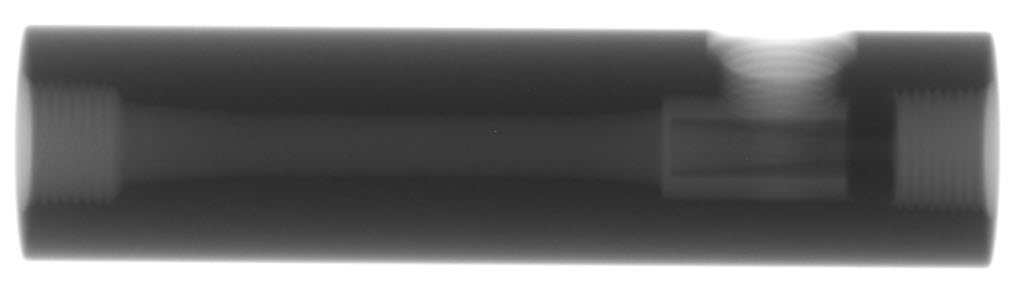
From looking at the top image above, if I had to guess the part is turned + milled from a large 31.5mm aluminum extrusion, and then the feature I am calling the “straw” is threaded down into the rightmost tapped hole (the air-in port) and somehow welded in place. What’s weird about this theory is that the interface looks completely seamless! Normally a perfect application for CT scanning would be in quality control of a weld like this, so maybe they just have their parameters very dialed in.
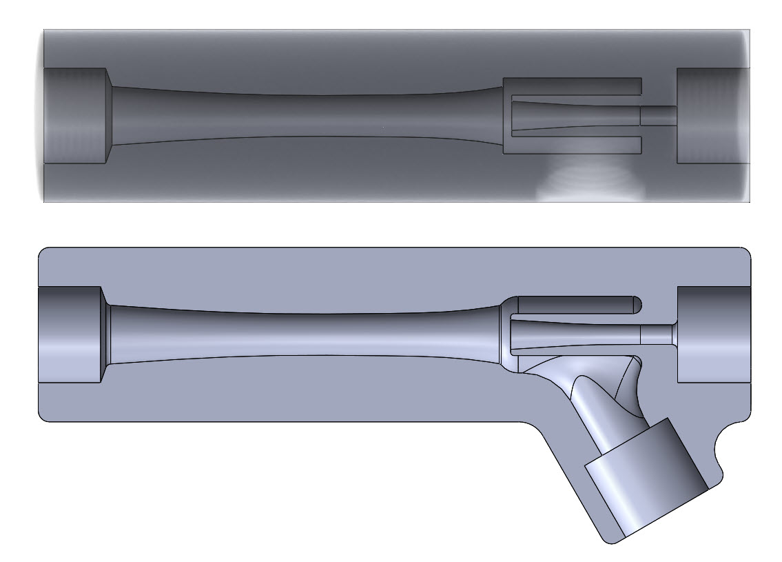
Next was my workflow after taking the (unfortunately 2D image of the cross section of the model) into Solidworks. My CAD is pretty simple, it’s a revolve with a hole cut into the side for exhaust. On the top is my sketch over the inserted .JPG, and below is after a few tweaks for better flow. I was imagining there would be much more room for improvement, and there may be, but I am afraid to change too much without having run any CFD, at the cost of potentially tweaking something that’s important.
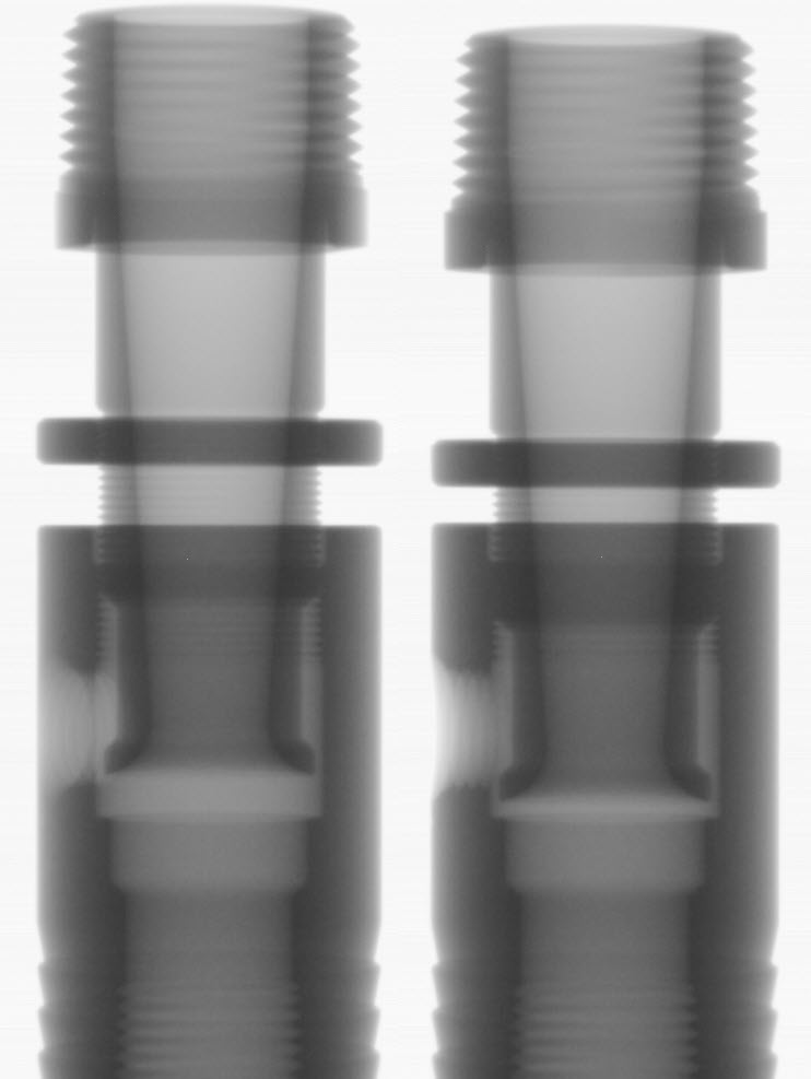
Below are some x-rays of another product that’s used to pull vacuum (but using the Coanda effect as opposed to the venturi). This one is adjustable to control air consumed as well as vacuum flow rate, so I took two scans, one in the mostly-open position on the left, and one in the mostly closed position on the right. I know these coanda blowers are typically used for higher flow applications, and I am really interested in pulling high vacuums, but I might model this one as well and try to better understand the tradeoffs.
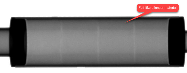
And lastly here was a scan of an industrial silencer, which is used to quiet penumatic exhaust. I was surprised to see that it’s just a cylinder of aluminum with a constant radius of a felt-like material that’s used as a sound dampener, but none of the sound dampening seems so be geometric. Perhaps the internal aluminum wall would benefit from an egg-carton geometry similar to what’s used in recording studios? From a conversation with Chris it sounds like this sort of geometry is typically used to target specific frequencies. If you have any ideas let me know!
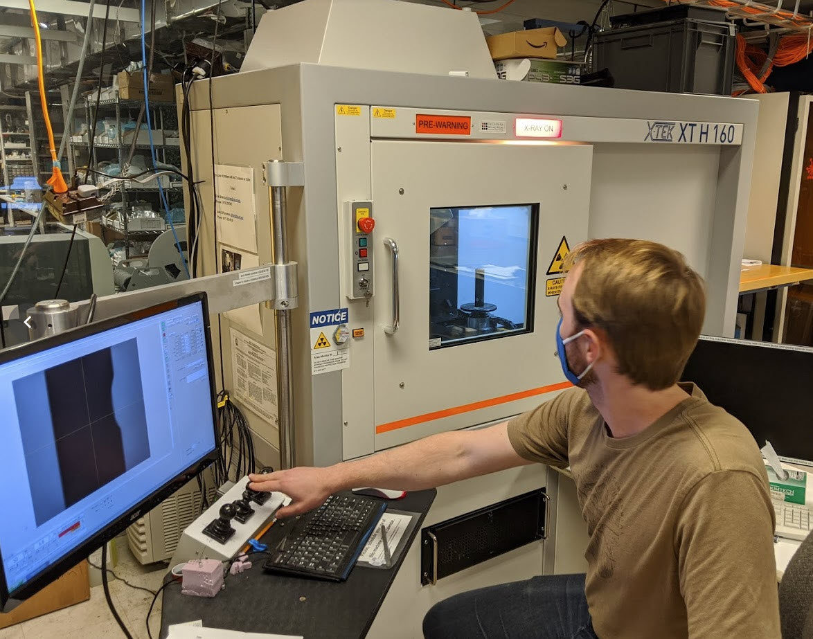
CT scanners are really just X-ray machines similar to the ones you might find at the doctor’s office. Instead of standing in front of the x-ray, we put our test subject on a 5 axis stage, which allows it to be moved around precisely in front of the x-ray cone. So all that the machine is doing is creating a big folder of x-ray greyscale images of the part, and then using a bunch of 2D images to reconstruct a 3D model (voxel model!). By changing power of the x-rays we can take a bunch of “cross sections” (except they are not true slices they are capturing information from the entire depth of the 3D body). The X-rays are generated by creating an electron beam using incredibly high voltages (up to 160kV!) and striking a piece of metal, either x, y, or z. When struck, the metal emits x-rays, who’s wavelength and energy is dependent on the emitter metal.
Changing the voltage of our electron beam changes the spectrum of the x-rays (more voltage means more energetic) More energy means they can pass through more stuff (metals take lots of energy = higher voltages, wheras biological samples don’t). For example we were using ~150kV to scan an aluminum cylinder that was 31.5mm in diameter.
Changing wattage just nets you more photons, which allows you to scan faster. The tradeoff being that lower wattage yields better focused images, and it’s better for the lifetime of machine. Focus improves because the emitter will better approximate a point source (presumably the electron beam widens and irradiates a larger portion of the sample?) which helps in the fact that we are assuming a conical beam path with x-rays originating from a point source.
This machine, the Nikon Metrology XTH160 Micro CT is a point source (conical beam) emitter (as opposed to cylindrical source which gives you an orthographic scan in the axial axis of the cylinder).
My scan was ~1800 images and took only 22 minutes, although this was on the lowest, most artifact prone scanning settings.
Reconstruction happens with a software called CT-Pro made by Nikon/X-TEK same makers of the scanner). To view the scan you open ANOTHER program called VGStudio. At this point we have a voxel file, which can be thought of as a 3 dimensional grid, with each node assigned a “density” value. The software allows us to threshold estimated density of each voxel (so you see a histogram with peaks representing air and metal in this case, and threshold out all of the air). You can imagine how these boundaries become less clear with biological samples, where the relative density between bone and muscle might be much less clear, demanding much higher resolution scans.
I got a 1.5GB .VOL file (along with a much smaller .VGI file). Unfortunately I have no idea how to get a mesh out of a voxel-based file, and so was restricted to rotating around in VGStudio. I didn’t recognize any of the other export options.
We didn’t have to use it, but beam hardening involves putting an additional piece of metal behind the subject. If the subject is very x-ray absorptive you will get really high contrast because the areas with no metal are getting a ton of power and the actual object is blocking most of the x-rays. So the object is like totally black and the background is totally white. By putting a big chunk of metal behind your subject you effectively bring up the threshold for x-rays that get to the detector and up which is akin to “turning the whites down” in photoshop.