This project covers the design and assembly of an OMM (Optical measuring machine), or more specifically in the case of this project, a Telecentric Imaging Stage. OMMs fall into a subset of CMMs (Coordinate measuring machines), where instead of using a probe and making physical contact with a part at known coordinates, they use a camera and takes images of a part accordingly. I’ve linked videos of the assembly process, and an example of using the tool below, and there’s lots more documentation of the project if you keep reading. Feel free to get in touch if you’re interested and want to talk more about anything you see here!
To unpack the name Telecentric Imaging Stage, the “Telecentric” refers to the use of a telecentric lens, which is a fancy type of lens that’s commonly used for measurement/gauging applications. Telecentric lenses are unique in that they don’t suffer from parallax error (objects appear the same size regardless of distance), but do suffer from having a field of view only as big as the lens itself, so roughly 40mm x 30mm in the case of the lens that I am using. Imagine seeing the world permanently in Solidworks’ orthographic view, but you can only see through a tiny ~30x40mm window at any given moment.
An even more straightforward definition would just be to say that this project is about building a precise stage that moves over a part in X and Y, takes overlapping pictures with a special camera, and then stitches those images together to create as accurate a 2D representation of the part as possible.
So with all of that said, this project is really a case study looking into several ideas (listed below) surrounding precision machine design and metrology, and building an OMM was a neat excuse to try and implement them.
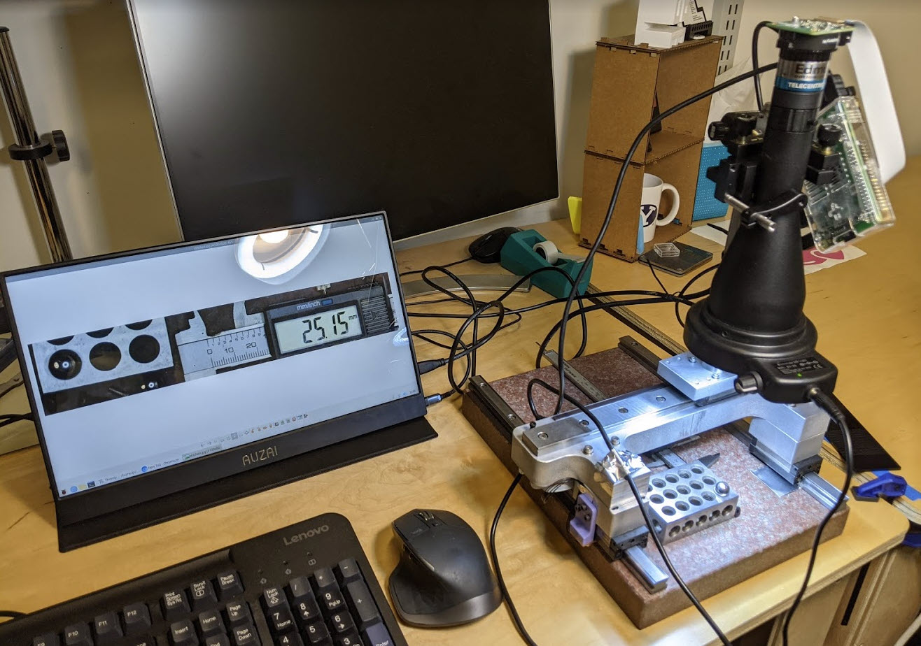
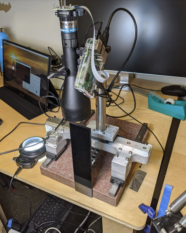
Below is an image of the final assembly, and on the screen is a composite image (stitched together from 5 overlapping images) of what’s resting on that surface plate (a 123 block, calipers, and some bearings + screws). See the videos above, or read on below for more details.
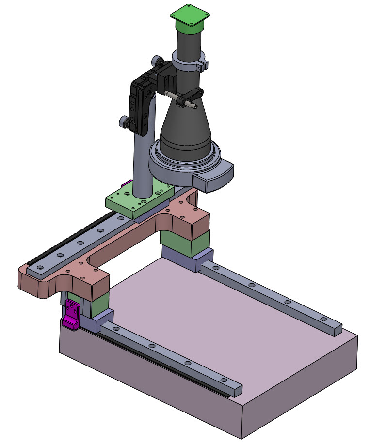
Shown below is the CAD for the final assembly. It’s modeled in soldiworks, and is primarily one big multibody part with the OTS parts like the lens (Edmund Optics) and fine adjust (Thorlabs) thrown in an assembly at the end. There are definitely some downsides to CADing this way, but it’s helpful for moving quickly through early prototypes with only a few moving parts, and can always be repurposed into a master model later if needed.
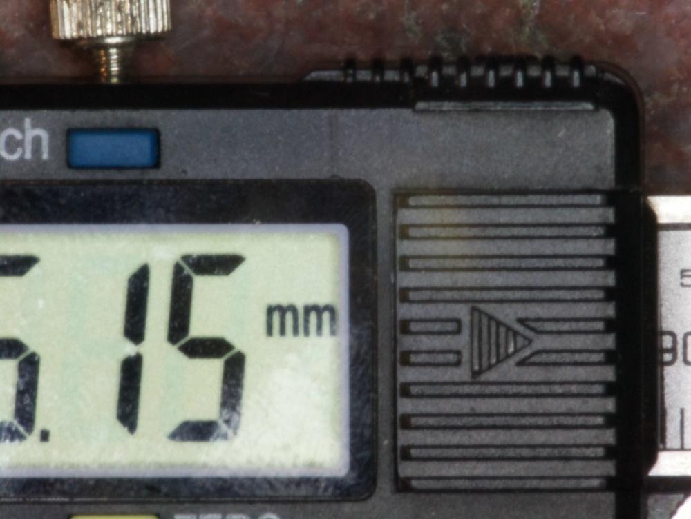
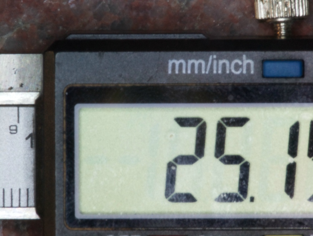
In week 5 for machining and casting, I made an attempt at mounting some linear rails to a surface plate, which went surprisingly well. The process was to use a cheap dremel-style diamond abrasive bit to gently interpolate holes into an inexpensive granite surface plate. With the holes machined, I then epoxied in threaded inserts, and bolted my linear rail to that. You can see how it assembled with one rail below, resulting in parallelism of my bearing block to the surface plate of only 5um. Let’s call this axis the machine’s X-axis.
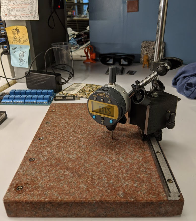
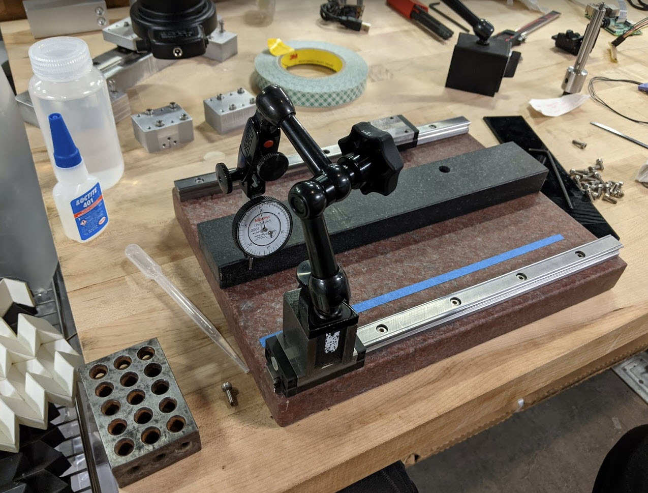
It’s critical that both of the rails are not only straight (both in the X and Z axes), but also parallel to one another. To ensure that, I first established the straightness of my primary rail using a granite parallel and indicator as shown below. With one installed, the other rail was indicated in off that, and both were swept in Z as well. From the video I wound up with <5um parallelism in both X and Z which I was really happy about. At those tolerances it actually becomes super important to clean and debur all of the mounting surfaces very carefully. I settled on a x-acto blade and scotch brite for the deburring, and the cleaning with IPA + Kimtech wipes. Contrary to popular belief, linar rails are not infallible wrt their straightness. All of the rails used here are from THK, and before bolting some were bowed to nearly 100um (granted I did saw them with the waterjet so who knows what sort of stress relieving is happening).
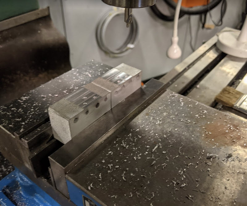
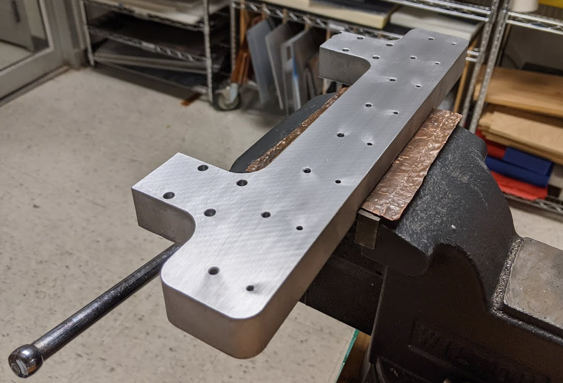
Waterjetting was a common theme here. For the gantry, Z- mounting block, and X-spacer blocks I waterjet everything out of 1” and 0.5” MIC6. For the X/Z-spacer blocks I needed to machine the encoder mounting faces and holes which were off axis from the jet. To get rid of the kerf I chucked them up in the mill referencing off their blanchard ground surfaces as shown below.
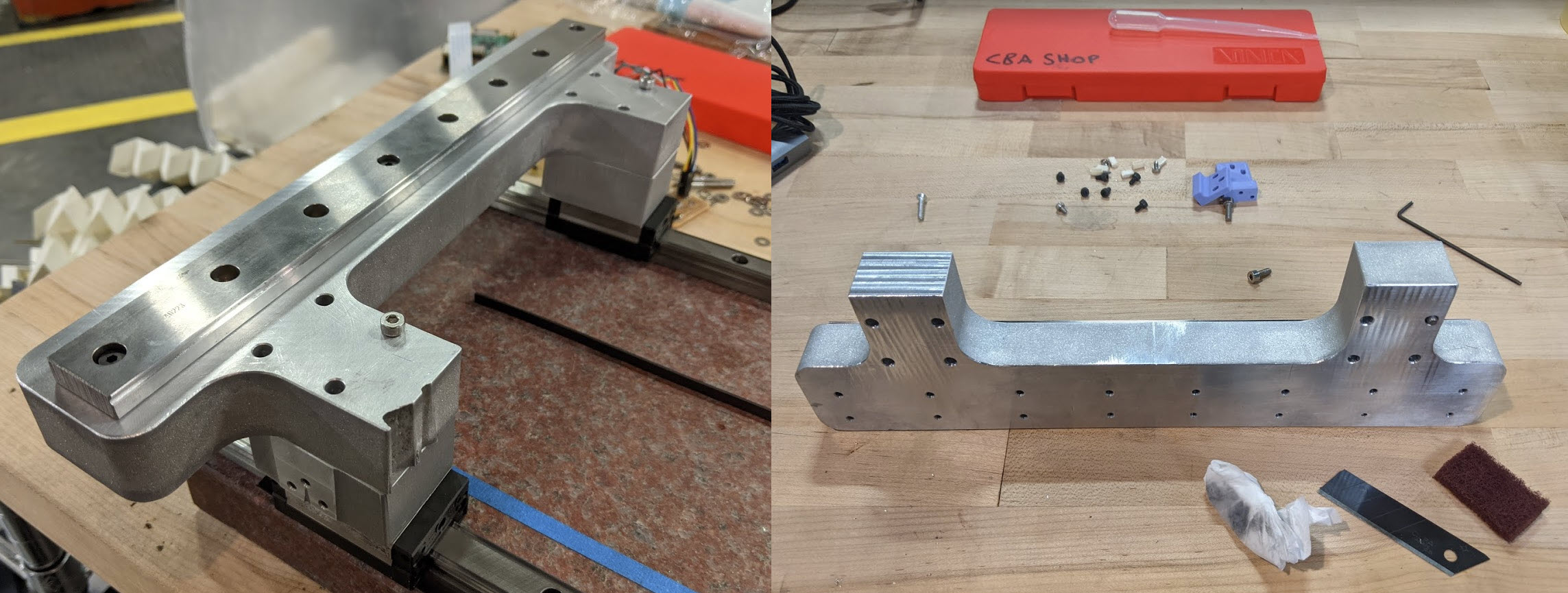
The gantry was also waterjet out of 1” MIC6. To maximize usable travel, I offset the Y-axis rail a fair distance past the X-axis blocks, such that the lens landed closer to the center of the two blocks. While this wouldn’t be great for machining, all of the loads on the gantry are low and quite static, so I think this it’s a decent tradeoff for this application. Unfortunately it resulted in a weird geometry that I tried jigsaw-puzzling out of a very hole-y piece of MIC6, and ultimately paid the price of overlapping with someone else’s prior job, and having a small chunk missing from the front of the part. You can see it missing in the first photo below, before I couldn’t stand it any longer and machined it away (no real performance penalty and I think it looks better).
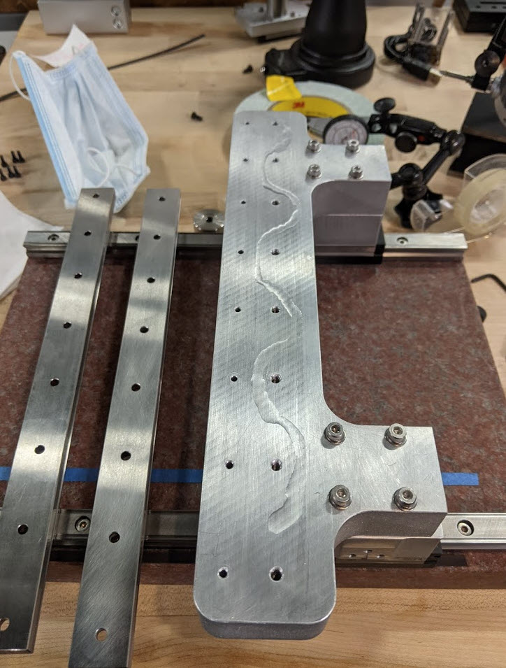
Here’s a photo from mounting the Y axis rail (pre-cleaning with IPA) with the gantry already installed.
For proof of all of the indicating/aligning, check out the second video linked at the top. As a more mechanically inclined person (in comparison to all of the EE and software that comes later), this process was a lot of fun, and something that I am excited to try again on future projects.
So with a good start on the base, we have a precise 2 axis stage, with very high parallelism to the surface plate, and perpendicularity between each axis. You can now imagine that we have a camera that we want to attach, such that the camera/lens are pointing perfectly down in Z, orthogonal to the XY plane of the surface plate. There are several approaches to take here, and I’ll try to talk about the tradeoffs below.
You may be wondering what all that weird stuff attaching the lens to the Y-axis post is in the CAD drawing shown at the top of the section, and that’s what’s discussed below. Most of the incoming writing was done in week 8, but all I’ll say before talking more about optics mounting is that I considered adding an actual Z-axis, but given that my lens has a 40mm depth of field, the Z axis would only be buying me an additional 10mm of inspect-able part height, and I don’t think that’s worth the added complexity.
Approach A: machine everything really accurately
We could machine our parts accurately enough such that the kinematic loop running from the surface plate, through both X and Y axes, and into the camera mount, such that the camera was within whatever mounting spec we needed. There are a couple of problems with this option, which really all boil down to it being very difficult to ensure all of our reference surfaces are accurate enough to ensure a high degree of parallelism at our lens. You can imagine that if each surface is out of parallelism by 25um, over 6 mounting surfaces (assuming our errors are compounding) we might have ~150um of error. If we are clamping to the lens over a 25 mm span, this could angle our lens by 1.4 deg! A more intuitive explanation of why this is problematic is that if we were looking at a part 25mm tall, we would artificially increase its length by 150um due to a perceived “overhang.” One more thing to mention is that we have no real understanding of how accurately the internal optics of our lens are mounted inside the lens tube. Therefore even if we could fixture the outside of the lens body perfectly, there are still internal tolerances associated with the alignment of the glass optical elements internal to the lens itself!
Approach B.1: Feedback-driven adjustment
This is the approach I intend to take for the final project. The philosophy here is to take a calibration target of known (high) tolerances, look at it with the telecentric lens mounted in-situ, and then using that as feedback to adjust the lens mounting such that it is delivering an optically “correct” image. Thorlabs makes a nice kinematic fine angle adjust mount that we could mount the lens to, and so long as we have enough travel, we should be able to rotate the lens about thetaX and thetaY, such that we can float the camera into proper orientation (for example if looking at a perfect cube with a blue top and red sides, we would want to ensure that we could only see blue through the lens). This approach has one major advantage, in that it allows us to have loosely toleranced parts between our linear axes and the camera lens itself. It also resolve that last point from approach A above, allowing us to bypass the lens housing, and reference against the optics themselves.
Approach B.2: Same as above + adhesive
This is essentially the same thing but more amenable to manufacturing in higher quantity. We could use a jig that strictly sits on top of the surface plate and uses the same kinematic fine angle adjustment to establish orthogonality between the lens (using feedback) and the surface plate. We could then slide the lens which has been frozen in orientation against some mounting features, and tack it into place with epoxy, wait for the epoxy to cure, and then reinforce that with a threaded attachment. What’s nice about this method is that it means we only need one of the expensice Thorlabs kinematic mounts to be our jig, and that process’ precision is locked in after it’s been floated into place. The tradeoff is that we lose the ability to adjust over time, if the tool gets taken apart or things drift out of alignment. This is actually how many optical elements are really manufactured (probably including the telecentric itself to some degree).
Now that we have the stage and optics mounted, we need a way to establish where our camera is in the XY plane down to the (hopefully) micron scale. This is typically done with a linear or rotary encoder, which is just a device that measures linear or rotary (and then converts that to linear) displacement, and feeds that back to a human turning a wheel, or a machine controller a motor. Encoders are commonly capacitive (dial indicator/calipers), optical (glass slides/DROs on a machine tool), inductive (I’ve only seen this on some fancy calipers), or magnetic (what we’ll discuss below).
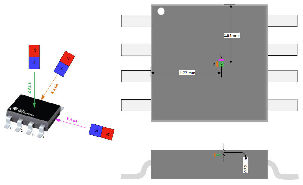
Digital quadrature magnetic encoders are really commonly used on the backs of cheap brushed DC motors, and when coupled with lots of reduction can yield excellent angular accuracy. Without the luxury of mechanical reduction in the linear world, I intend to take an analog measurement, rather than a digital one, and by doing some curve fitting/interpolation, hopefully get a much higher resolution (only limited by the sensor’s ADC rather than pole spacing). This sort of interpolation is sometimes called sin/cosine encoding, and to explain why, see the image below, which is exactly how the magnetic scales I am using for this project are magnetized.

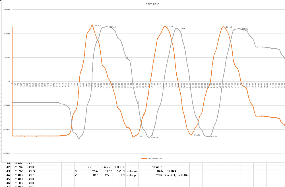
Looking at the image above, imagine you sweep an analog hall effect sensor over that halbach array, while measuring flux in Z. It turns out that your flux reading will vary sinusoidally, with peaks at the center of each triangular pole, and zero-crossings in between each pole. What’s also neat about this observation is that while flux in Z is zero in between each pole, flux in X (in the direction of the encoder travel) is at a maximum! We are interested in getting linear displacement, and we can actually pull a linear response out of these two signals (flux in X and Z), by taking the arctan of one over the other. We then get a linear signal, that varies over the range of our ADC, before resetting every 2mm (the length of the magnetic poles in the halbach array). By counting the number of these resetting events (and adding or subtracting 2 accordingly), we can achieve extremely high resolution sensing. I only log down to 10’s of um, but this sensor easily has resolution down to the nanometer, albeit most of that’s noise.
Below is an image of some of the raw sensor data that I pulled into excel to check phase angle of the signals, and see if they needed to be scaled or offset in Z. It turns out that the X and Y axes on almsot all 3-axis hall effect sensors are considerably noiser that the Z axis. I suspect this has to do with how the actual hall effect is being measured in silicon (it’s probably easier to lay out transistors in a plane in the XY axis considering how lithographic dies are layered). The X and Z axis sensors are also in different physical spaces on the IC, which should warrant further calibration (a phase shift I think) that I am not doing a the moment. For better accuracy it’s likely that I should be switching to two Z-axis sensors, offset in physically space by 0.5mm (90deg for the sin/cos signals), but this approach has the advantage of being tolerant to any pole spacing. Another thing to look into for a future project!
If you’re interested in the sensor I am using, a PTMAG5170A1EDGKQ1, SPI communication, and reading it with the SAMD21, I’ll direct you towards week 11, where I did the bulk of this work.
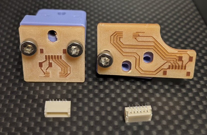
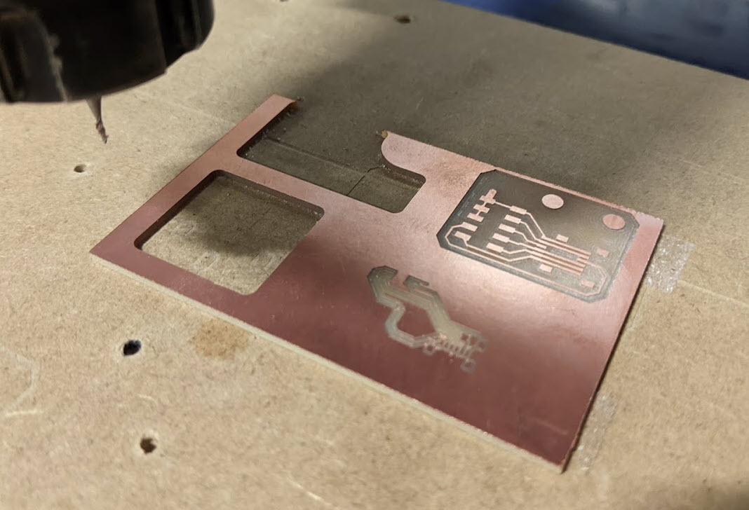
Below are the boards I made for the X and Y encoders, which tuck behind the rails and float just above the magnetic scales. I soldered surface mount JST connectors which we had in the lab for the first time here, and found them to work really well. All that’s on these boards are the connectors, the sensors, and a 0.1uF bypass cap.
For time I wound up re-using the board from week11 for the final, and to do so I made a junction board that connects the two encoders via ribbon cable. There are 7 total conductors leaving the SAMD21, where both encoders share the SPI bus. It took an embaressingly long time to wrap my head around wiring the ribbon cable, as shown in the screenshow below.
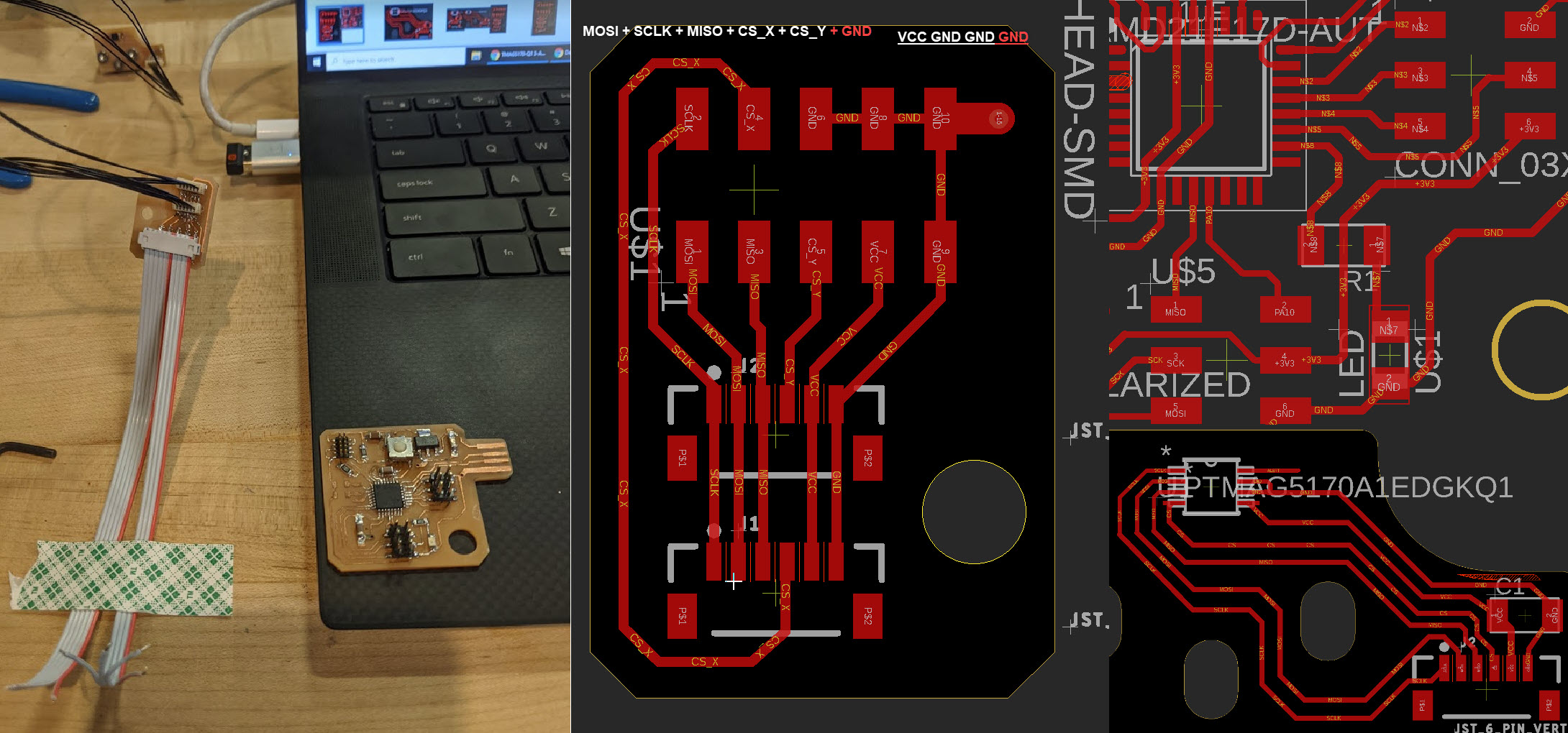
Debugging the SPI bus was not fun (I made the mistake of integrating everything pretty early on). One of the highlights was this nearly invisible solder bridge shown below. In the end I started running out of time, and while I had both sensors working independently on the same chip select line, I just moved forward with one to keep things simpler.

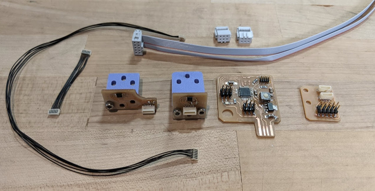
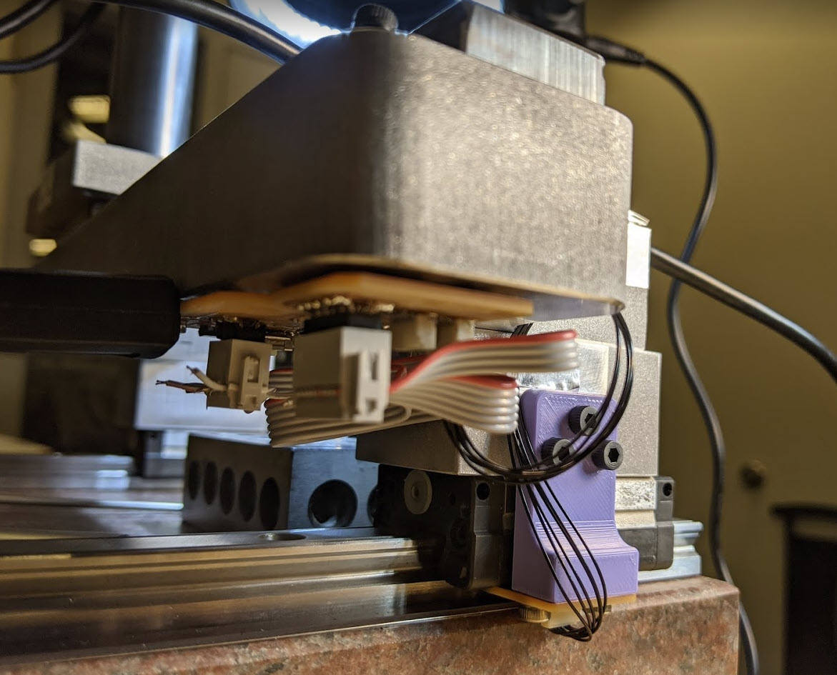
Here are all of the electronics layed out below, as well as how they’re mounted in the final assembly. The SAMD21 board is powered over USB via a raspberry pi 3B, but I’ll discuss that in imaging below. It’s continuously spitting out X position over serial, and the code is otherwise ready to have more axes CSV’d on. You can check out the code here spiExample.ino.
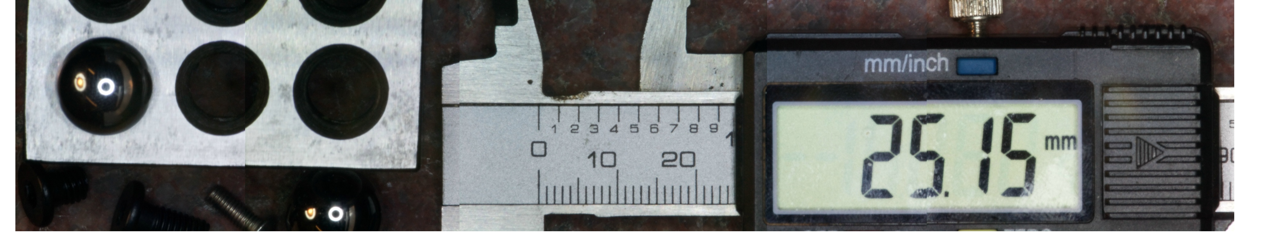
And lastly see the assembly video linked at the top showing the encoder running in comparison to a dial indicator. I seem to hit peak errors of ~120um. After more testing, what I’ve found to be really interesting is that error seems to vary sinusoidally with a period of 2mm, suggesting that there’s still plenty of error left to calibrate out of the sensor. Fortunately this means that my accuracy over large distances (>2mm) is fine, but while interpolating between 2mm poles accuracy starts to suffer. This will be another neat thing to explore over the winter break, where I am particularly looking forward to normalizing this data against a real encoder and plotting actual error vs. displacement.
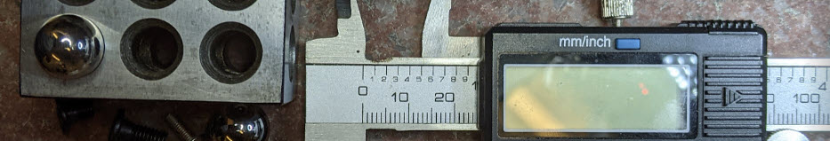
To cut to the chase, below is one of the better images I took with the setup - a composite image stitched together from 5 slightly overlapping 40mm x 30mm images using encoder data. You can see many of the seams (some are worse than others depending on the encoder lottery), but overall it looks reasonable from a distance. The photos making up this image span a travel of 120mm. I’ve linked them below with their encoder positions in their filenames: 3.42, 32.38, 62.99, 90.33, and 119.59.
I also took a non-telecentric image with my phone, which hopefully helps show why this is a useful setup for inspection in comparison.
I purchased the telecentric lens on ebay last year for $50, with the intention of mounting it statically on a surface plate and moving objects around underneath it. After not really doing anything interesting with it, I decided to pivot from the mill I was intending to build for this project, to an OMM, considering that they’re an under-represented machine tool in the DIY world, and telecentric optics are interesting. For this project I bought a raspberry pi high quality camera, which support C-mount lenses like the telecentric. It has a 1.55um x 1.55um pixel size, but only an 8mm sensor, so there’s slightly more FOV to be had with a 1/2” sensor. Unfortunately the lens requires a precise sensor to lens distance, and the camera has a floating adjustment here, so I intended to, but never got around to calibrating that distance and ensuring that I was getting the full 40mm depth of field that it’s rated for. I did lasercut a platen for putting objects at known distances away from the lens to dial in the sensor distance, but wound up just using it to rough in the height of the lens as shown in the picture below.
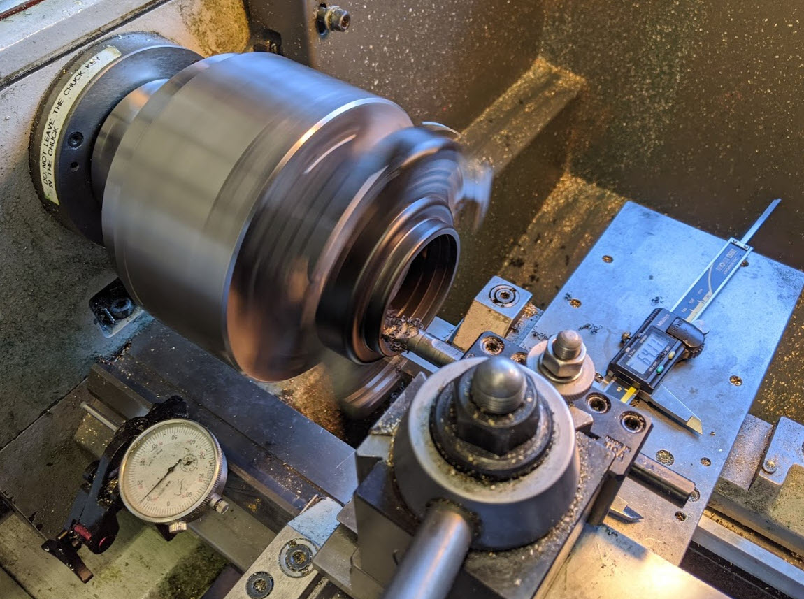
Because all of the light hitting the sensor needs to be perfectly columnated, it’s astonishing how little outside light effects image quality. In a brightly lit room with my desk lamp pointed at the surface plate at a ~30deg angle, I need to have the aperature pretty wide open in order to resolve anything of interest. In reality telecentric lenses are often just used for generating silhouettes, and have notoriously fuzzy edges under normal lighting conditions (considering it’s impossible to get perfectly columnated light off of an object unless it’s light emitting itself…). A reasonable solution I’ve found is a concentric microscope light - the one I have mounted to the camera took some modifying on the lathe to get its ID large enough to fit around the 65 mm OD of the lens. I opened it up from about 62mm, and wound up with a gentle press fit and enough threads left in the sleeve to actively pinch the lens with the light’s very soft nubby set screws. I’d estimate that it’s contributing >80% of incident light in a well-let room.
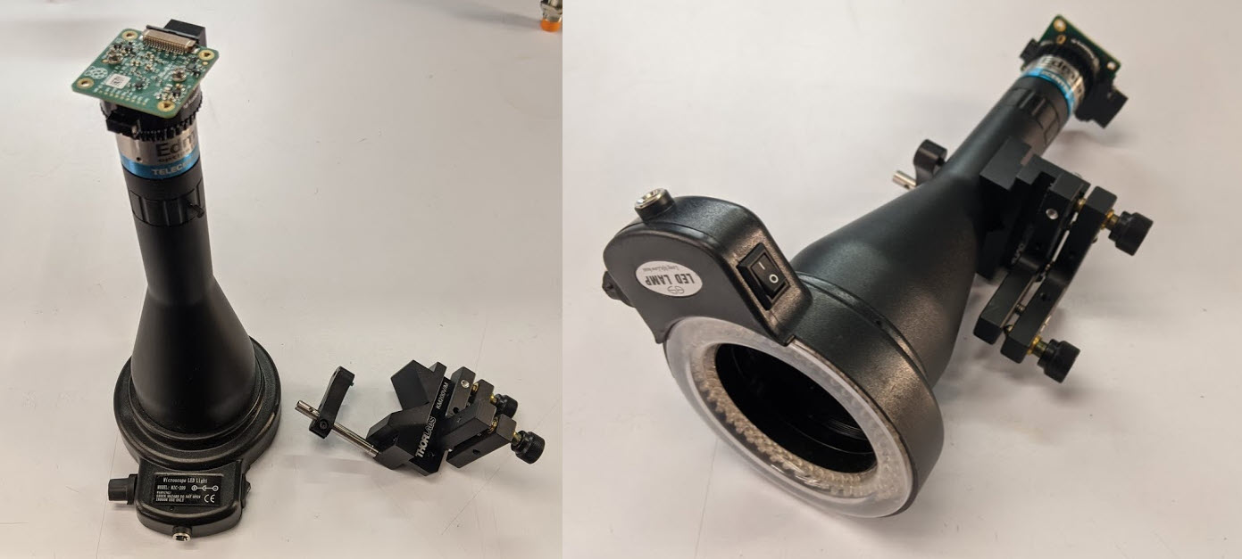
During week 8 I took some time to look around the CBA’s massive optics components stockpile, and fortunately found exactly what I was looking for mount the lens. In the photo below I am using a nice V-block mount which gently pins the lens with a nylon tipped set screw. As mentioned in the build section above, I also found one of those fancy Thorlabs kinematic fine angle adjust mounts and was able to get that attached with minimal modifications. In the picture below I have the fine angle adjust mounted in such a way that only gives me control of one of the relative rotational DOFs, so I wound up machining it to get the mounting holes I wanted oriented properly. You can see the difference between the photo below and the ones of the final assembly. Because the lens has a 177mm working distance, I knew I would need to mount it awkwardly high above the surface plate, so rather than making a moving Z-axis/doing anything fancy, I again turned to the CBA’s optics stockpile and wound up using OTS postts, which worked really nicely.
This project really warrants a block diagram, but I am running out of time so I will just explain the data flow in a paragraph here. A Raspberry Pi 3B is mounted on the gantry (it moves around with the lens), I am have a wireless mouse/keyboard plugged into it + HDMI running to a monitor + power. The RP High Quality Camera attaches with a ribbon cable, and it’s easy to take photos with picamera’s API. Lastly the arduino is also connected to the RP over USB, and that’s streaming X position continuously. On board the RP, I did all of my programming in python, relying mostly on openCV (although not really using any cool features at the moment). Disclaimer that I am a terrible programmer and wrote all of this literally the night before the project was due, so please forgive my bad code / poor choices below:
To take photos, I run imgCordCapture.py, which takes the photo, briefly displays it, checks the serial bus for the most recent coordinates, and then saves the photo to the local directory with the coordinates as its file name. You’ll see that I am downsampling my photos from their 4k resolution to only 1k, because otherwise the RP hangs and crashes when dealing with more than 1 photo.
Next I run stitcher.py, which searches the local directory for any jpgs, extracts their coordinate (filenames) to a list, and then places them on a blank canvas with offsets determined by the coordinates and some rough math that converts between pixels and mm.
I also included Encoder_log_script.py, which I was using to log the serial position data to a .csv file during debugging. I think this would be useful in the future for having a continuous image feed, and then using a mouse click to take images, rather than the tedious individual photo method.
Overall this project a great learning experience, and lots of fun to work on. I think what’s unique and worth further investigation still centers around those 3 bullet points from the introduction. I am looking forward to building more precision machine tools on granite surface plates. The DIY linear encoder and use of a 3-axis hall effect sensor to do so is not something I have seen done on the internet, and it works reasonably well, so that’s primarily where I’ll be going with the project over the winter holiday. Lastly the telecentric lens is neat, but I think for a future implementation I will try with a less expensive lens/camera, and see if I can leverage the stage’s precision to still get accurate telecentric-approximate images using more sophisticated stitching. Hope you enjoyed, and of course feel free to get in touch if you want to discuss further!