For week 7 our task was to get comfortable with an ECAD tool, and design / mill / populate a PCB.
I started a schematic in Altium Designer which I have used a little bit at my last job, but considering as there isn’t a library for the class (and Altium is notoriously difficult to find libraries for + get png’s out of), I opted to not draw a bunch of schematics and footprints and caved for Eagle.
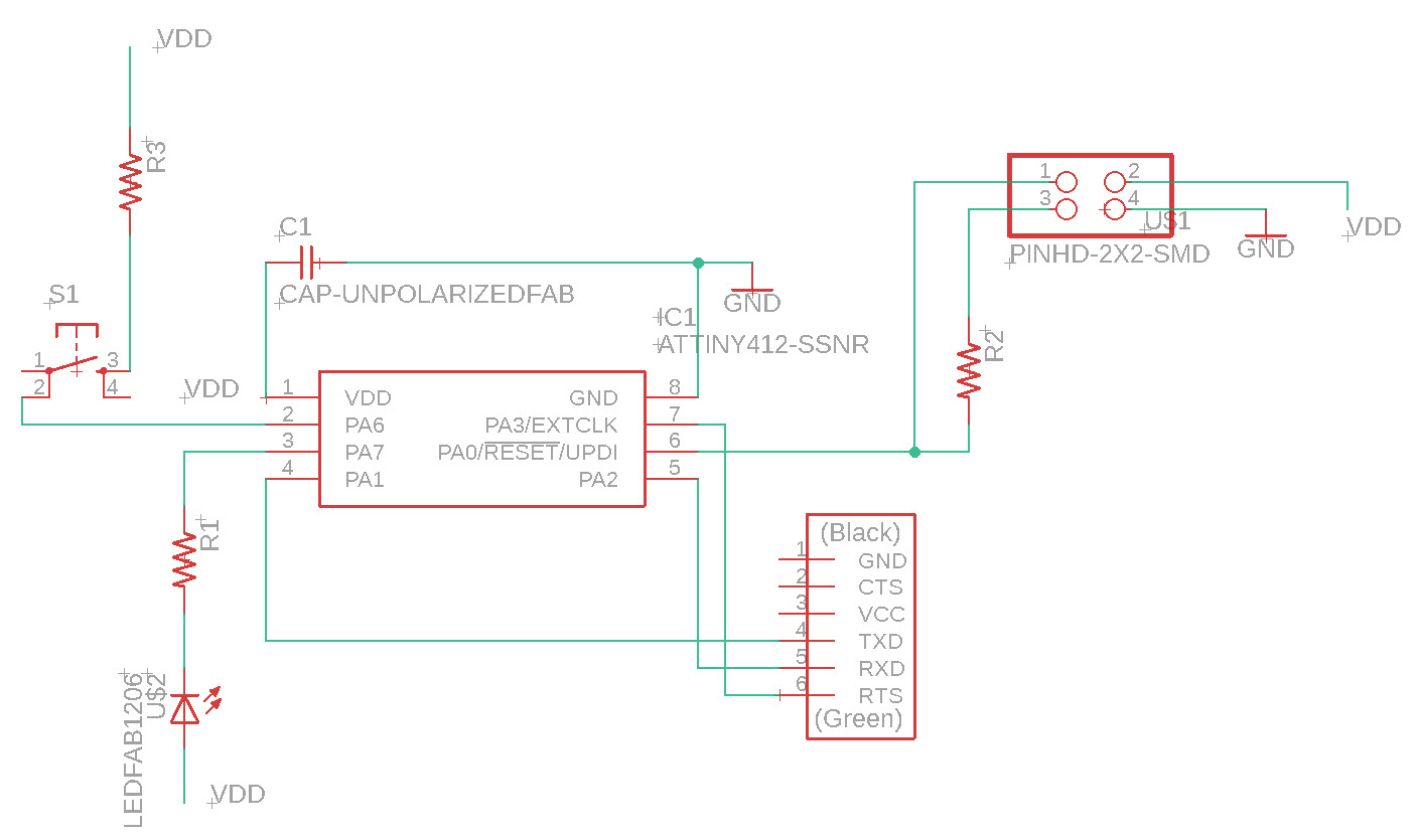
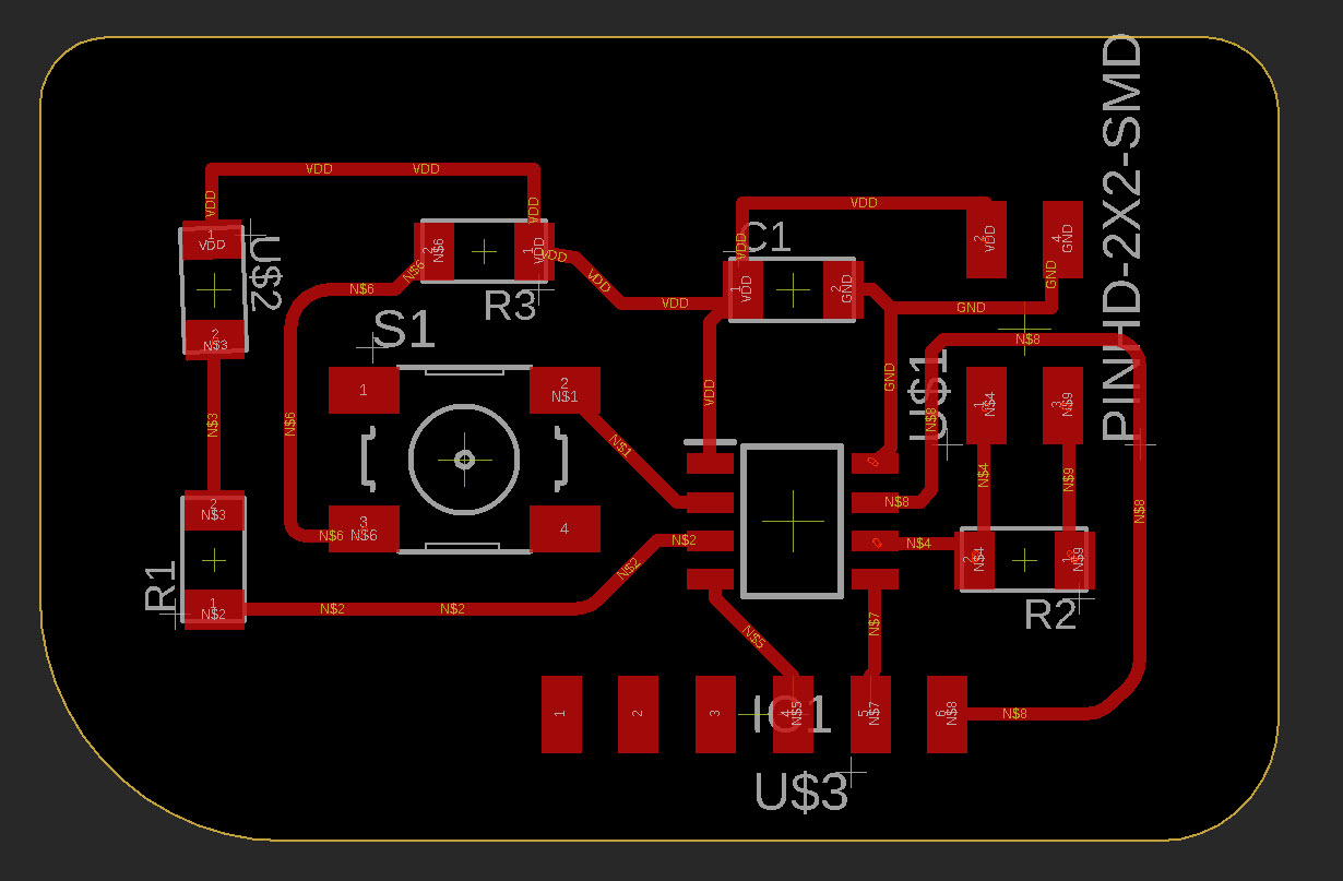
I have some PCB design experience so conceptually this week wasn’t too bad. I designed the circuit below around the ATtiny412’s we have in our kit.
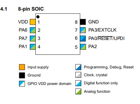
This seems to be the first year we are moving to microchip’s new line of refreshed Atmel era microcontrollers that use a single pin for programming and reset using UPDI, which is very cool. This gives us an astonishing 5 out of 8 pins to do stuff with.
You can see my schematic and footprint below. The 6 pin FTDI breakout was a late addition after Anthony reminded me that we were designing an Echo board that needed to be able to be able to communicate over the serial peripheral using pins 4 (TX) and 5 (RX). I added a button that pulls up pin 2, and a green LED that comes on when pin 3 is brought low + a current limiting resistor for each, a bypass cap, and a 4.7k ohm resistor for programming. In the end I broke everything out and had a few pins leftover.
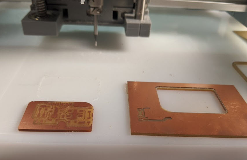
Shown below is my cutout + soldering progression (I am so sorry for the wrong orientation in the first picture). I soldered the 6 pin FTDI breakout pins by hand, and then did everything else with solder paste and hot air gun, which worked really nicely.
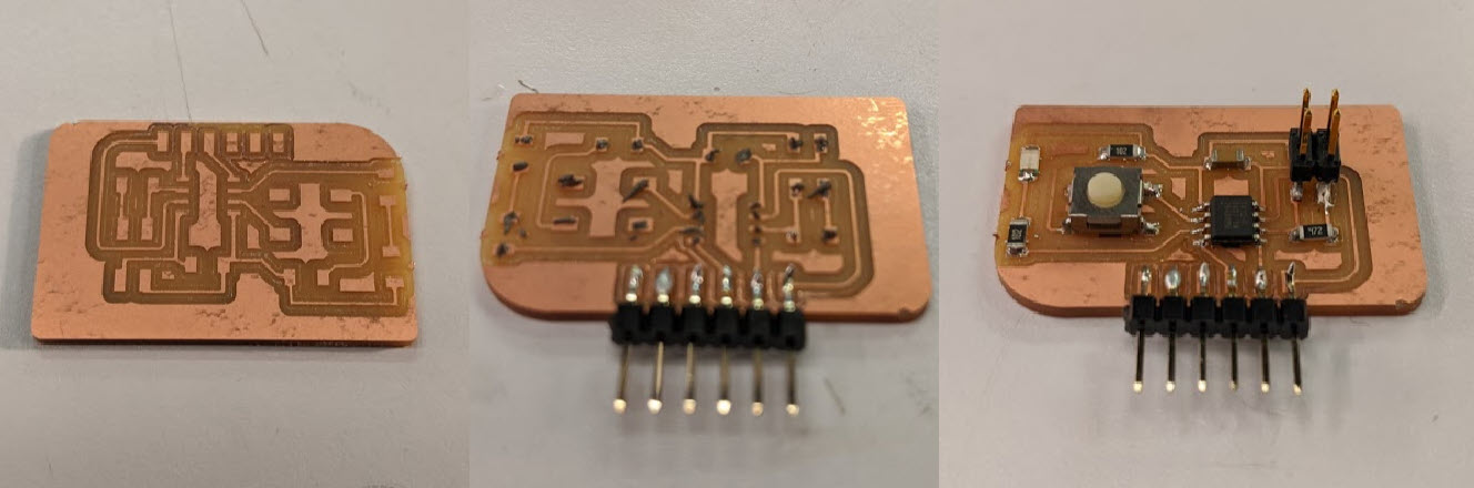
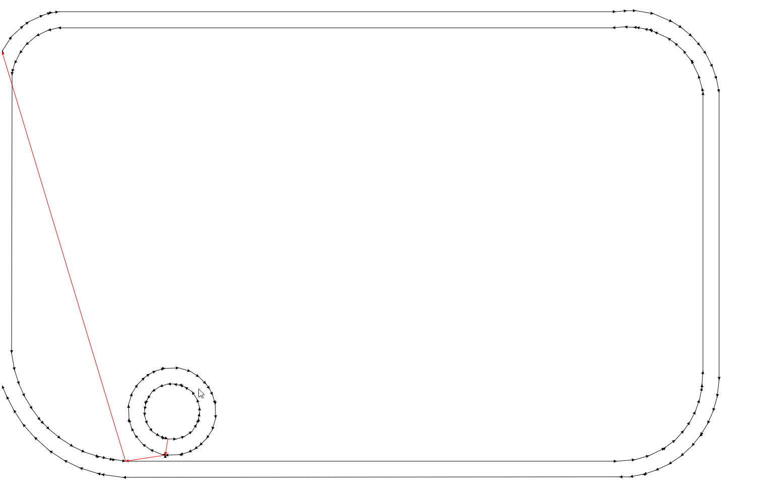
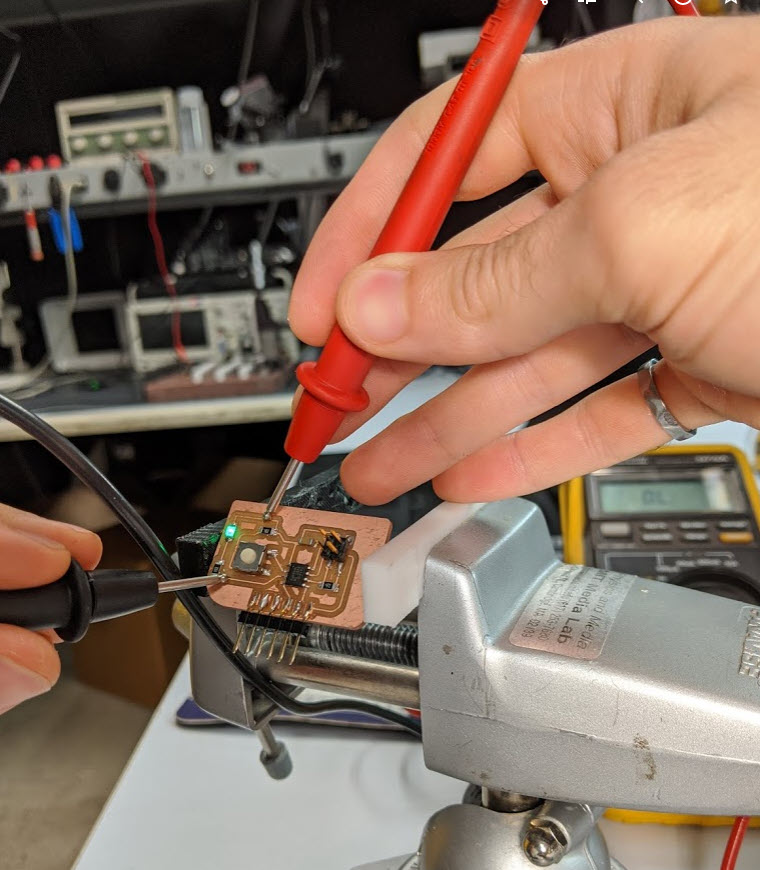
I then checked my board for continuity as per the screenshot at the top (and learned that the continuity tester of a fluke packed enough voltage and current to inadvertently forward bias and light up an LED…
I ran into one problem as shown in the screenshot below, where mods insisted on cutting both sides of my cutout. I tried a number of things, like getting rid of the mounting hole, inverting my .png (which resulted in no toolpath at all), playing with the image processing etc. In the end I just moved out my outline, set my tool diameter to 0.01, and machine twice on the line instead of outside of it. I think my cutout is slightly shifted, but fortunately didn’t buzz through any traces, and all of my cuts looked good. Last week I had some nasty burs around my traces, which may have been because I was cutting too deep with the engraving bit, whereas ths