For week 8 our task was to program a micrcontroller (I stuck with the ATTiny412 from last week) and read through its datasheet.
Disclaimer that I am working in Windows (sorry) and using Gitbash as my terminal for all of this, so hopefully if you are a future windows user this will be helpful! I was largely just following along with Zach’s guide here.
To get all of the necessary programs and libraries for programming an ATtiny:
With everything ready for programming, write your code in the Arduino IDE, and press the verify button. Is preferences make sure “show verbose output” is checked during compilation, which will let you find the location of your compiled sketches. Copy and paste that file into your pyupdi folder. My hex file was being stored in the arduino build folder here:
C:\Users\david\AppData\Local\Temp\arduino_build_681711
Now we jump into our pyupdi terminal and run pyupdi.py, which syntactically for me went:
python ~/Documents/pyupdi/updi/pyupdi.py -d tiny412 -c COM3 -b 115200 -f HTMAtest.ino.hex -v
I wrestled with the following error (after getting a decent way into running pyupdi) for several hours. So something suspicious was happening. Eric was also super generous and (along with helping me debug) tried the programmer from his computer with no luck (suggesting a hardware issue). The next morning I got intermittent programming after plugging and unplugging a couple of times. After that I went to the lab and just did another pass (admittedly my first was just hot air) on all of my microcontroller terminals with a soldering iron. So in the end I had a cold solder joint somewhere between power, pin 6 of the 412, or the programming 4.7k resistor.
INFO:link UPDI not OK - reinitialisation required Traceback (most recent call last): File "C:\Users\david\Documents\pyupdi\updi\pyupdi.py", line 182, in_main() File "C:\Users\david\Documents\pyupdi\updi\pyupdi.py", line 95, in _main nvm = UpdiNvmProgrammer(comport=args.comport, File "C:\Users\david\AppData\Roaming\Python\Python39\site-packages\updi\nvm.py", line 17, in __init__ self.application = UpdiApplication(comport, baud, device) File "C:\Users\david\AppData\Roaming\Python\Python39\site-packages\updi\application.py", line 17, in __init__ self.datalink = UpdiDatalink(comport, baud) File "C:\Users\david\AppData\Roaming\Python\Python39\site-packages\updi\link.py", line 32, in __init__ raise Exception("UPDI initialisation failed") Exception: UPDI initialisation failed INFO:phy Closing port 'C:/Program Files/Git/COM3' </code>
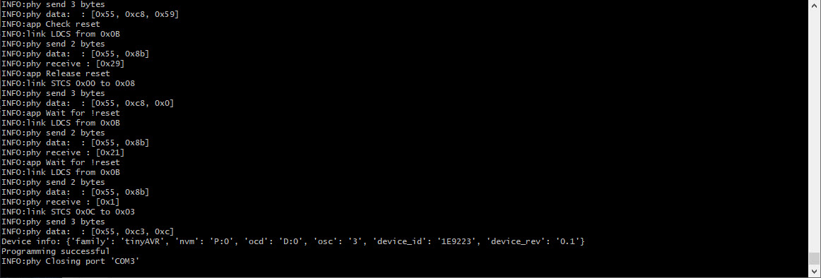
After resoldering, I finally finished executing pyupdi (which interestingly can take signifacantly longer or shorter depending on how many libraries you are using).
While debugging I noticed that the 412 datasheet seems to imply that to run at 20MHZ we needed a Vcc of 4.5V to 5.5V, although it sounds like CBA folks frequently run at full clock and 3V3. This coule be a neat thing to better understand. I did a little more putzing around the 412’s datasheet.
At the moment I’ve just written a script to pull my LED high when the button is pressed with all of the usual Arduino libraries. Tonight I will try jumping deeper into the datasheet and see if I can get rid of my pinModes + digitalWrites etc. (which is really what I would love to get out of this week in the end).