For week 9 our task was to measure something with a microcontroller on a PCB that we have designed.
For my final project I will be trying to read a magnetic Halbach array, and convert that measurement to linear displacement. Halbach arrays bias magnetic flux to one side of a magnet, and can result in tightly spaced repeating magnetic poles with sinusoidally varying normal magnetic flux (which will be useful for extrapolating between pole peaks to get resolution finer than our pole pitch). Essentially what we are making will be a quadrature linear encoder that replaces digital sensors with analog ones.
A good interim step here would be in getting repeatable and accurate measurements of magnetic flux out of a sensor, and so this week I will work on making what’s effectively a hand-held Tesla meter (aka a Gauss meter). Tesla meters are expensive (ranging from $70 on ebay to $500 for something actually branded). To do this I will need an analog hall effect sensor. I intend to use a 3-axis hall effect sensor to get the most out of the signal (from working on this project previously I suspect that using a 3-axis sensor will eliminate the need to use two sensors). Tesla meters usually have a body with battery and DRO, and then a sensor at the end of a “wand” that can be used to maneuver the end effector into tight spaces. For now I will intend to just spit out serial readings of flux in X, Y, and Z.
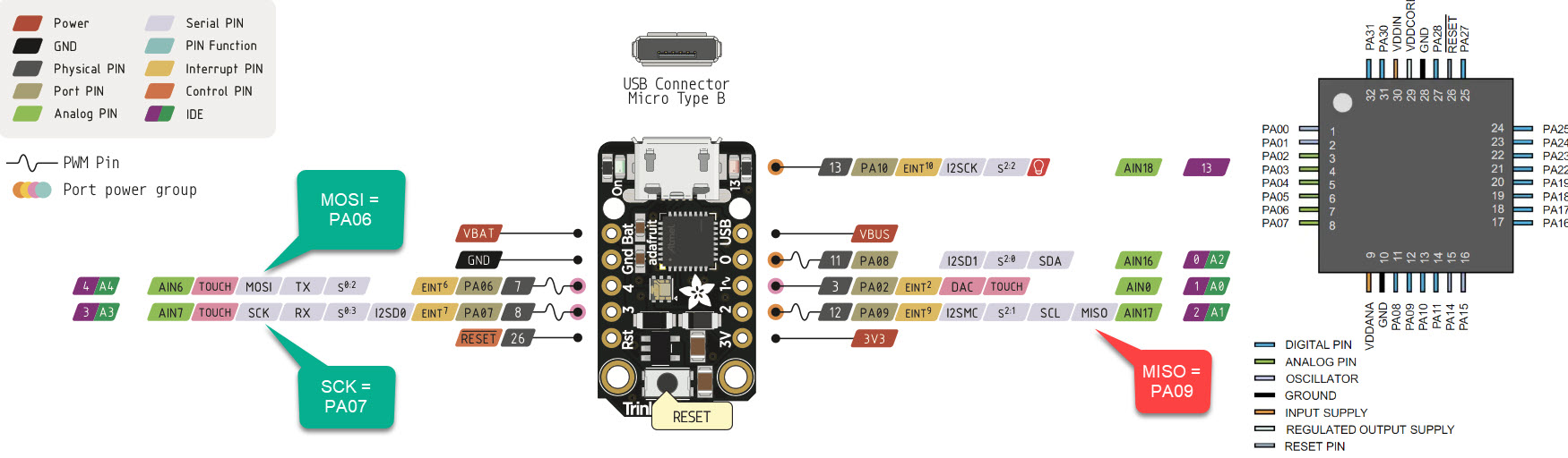
Jake convinced me to jump right into development with the ATSAMD21E17D-AF that we have in our kits. While their datasheet still feels way over my head, this is (almost) the same IC used by Arduino for the Zero and Adafruit for the Trinket/Gemma M0, so with the prospect of getting a Trinket bootloader onto my board (and therefore programming over USB) I set about designing my first ARM board.
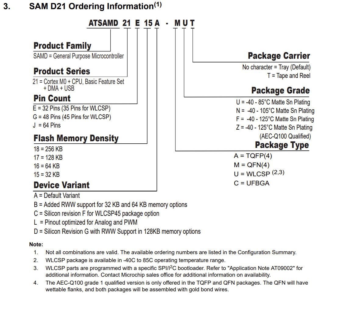
In the ~10 days since I last opened Eagle, I had to re-remember my workflow for finding and importing libraries. My go-to tool for avoiding drawing footprints has been Component Search Engine. The trick to finding specific microcontrollers is recognizing that a family of micros will often have the same pinout and schematic, so in my case I settled for the ATSAMD21E17D-AUT (which had full footprint and schematic) instead of the ATSAMD21E17D-AF (which had neither), recognizing that their packaging was the same, but their package grade and carrier were different (neither of these effect the IC from a CAD standpoint). So the lesson learned is that if you’re struggling to find CAD for your IC, make sure you’re not being more specific than necessary (in this case I was searching based on the grade of plastic housing the IC, and whether or not it was sold in reels).
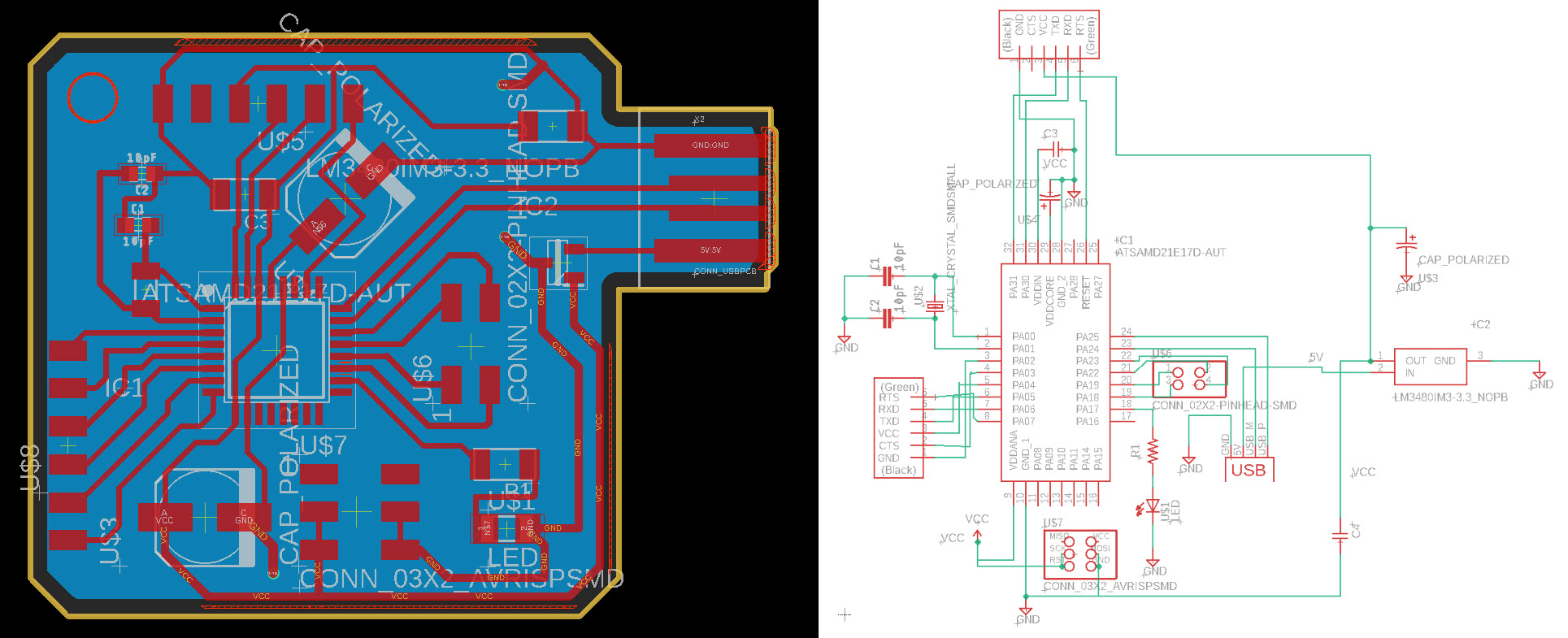
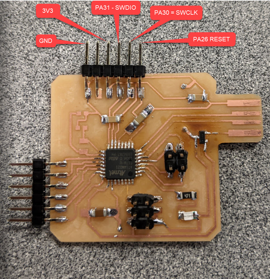
I designed the board above based on this tutorial, and the Trinket’s Eagle file. I set out to design what’s effectively a breakout board for the ATSAMD21E17D-AF (at the time of CADing I wasn’t sure which sensor I would be using). By the time I was done I felt significantly more comfortable moving quickly through Eagle, which is exciting!
I added footprints for an external 32kHz clock, but wound up not populating it (the Arduino Zero bootloader requires it but the Trinket and Gemma do not as per a conversation with Jake). Sort of ironically what I’ve made here is effectively an Arduino Zero… What’s exciting about this process is that after I have all of my debugging done I should have a very fast (48MHz) and reasonably cheap (~$2) infrastructure of microcontroller and PCB boilerplate to recycle into future projects. Fingers crossed!
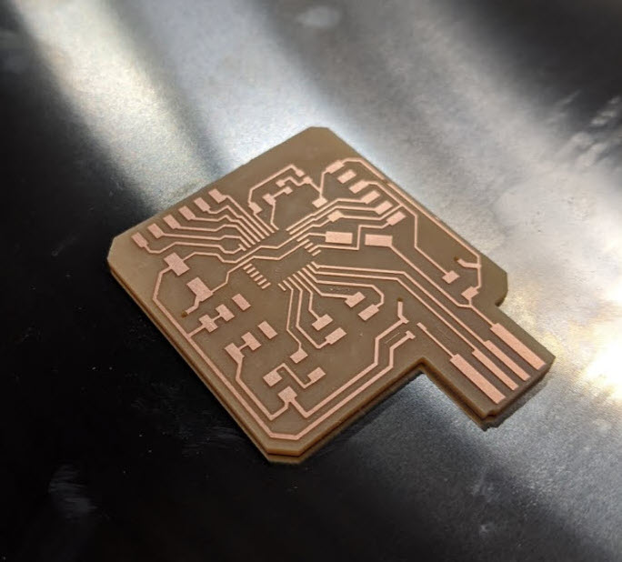
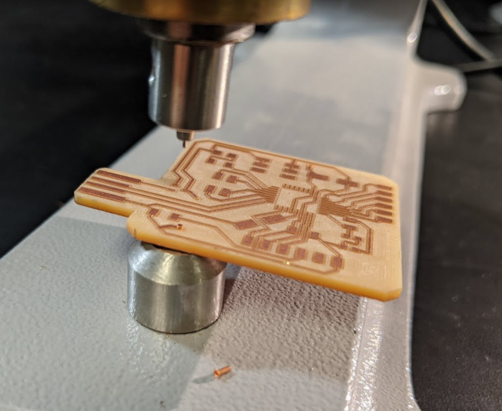
Here’s my finished board - this week I went the extra mile and pocketed out all of the excess copper surrounding my traces which took a lot of pain out of the soldering process.
I used a rear ground plane which really simplified my wiring + prevented me from having to do any double sided machining, at the low price of manually adding 3 conductive thru-hole rivets. You can see the process of pressing them in below, this is something I would definitely recommend if it means you can simplify your board or avoid needing actual traces on both sides.
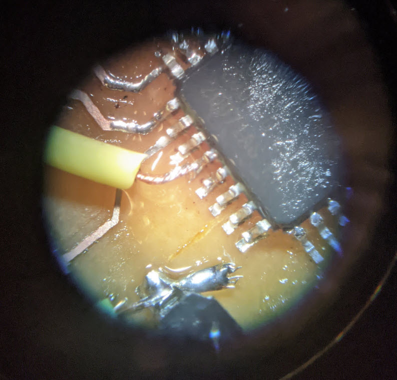
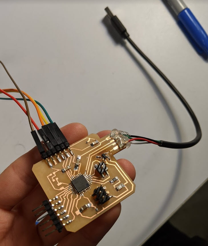
In reading through the SAMD21’s datasheet, it appears that they support up to six serial communication channels simultaneously (I2C + SPI + USART etc…), which they refer to generally as SERCOM. Here foreshadows my first big mistake for this week, in that I assumed it would be easy to move around my MOSI, MISO, and Clock pins, so I skipped breaking out pins PA08 - PA15 (the 7 I/O pins at the bottom of the micro). Ultimately for the default pin assignment of the Trinket M0, I wound up needing to solder in a jumper to get access to PA09 as shown in the picture below.
For posterity Adafruit has a guide on multiplexing in other SERCOM interfaces and which pins they show up on. I started down this road for a while before giving up and opting to solder in a jumper as shown below.
Jake stopped by the lab and I acted as a test case for his procedure for using the new MAX32625 JTAG programmers. It took us several hours (largely due to poor soldering on my part, including soldering in the ATSAMD21E17D in at a 90 deg angle. My next revision of this board will use the standard JTAG debug header that’s default for the MAX32625 and Atmel ICE, to avoid all the jumper shenanigans we got up to while debugging. At the end of the day (s/o to Jake for extreme patience) we wound up with a ATSAMD21E17D that could bootload as an Adafruit Trinket, and be programmed over USB from the Arduino IDE. Nice!
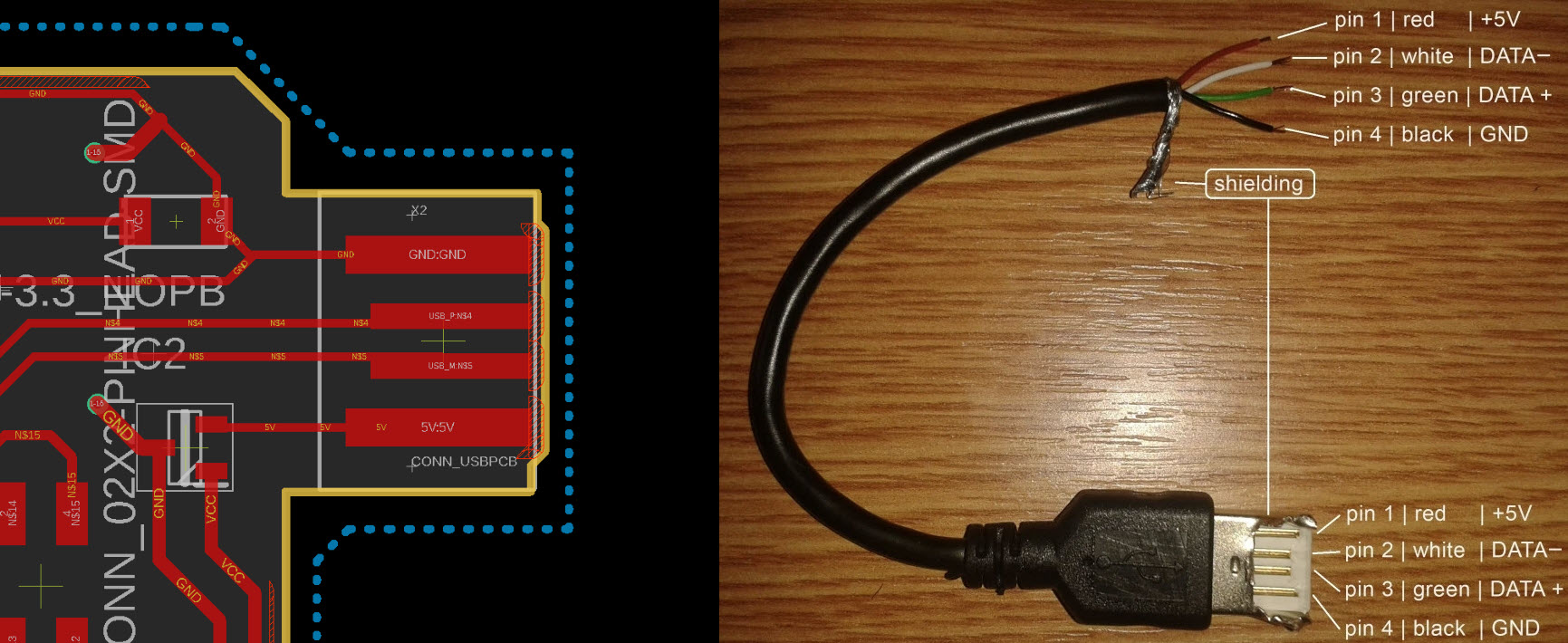
As an aside, the Fab Eagle library appears to have a revered machined in USB type A connector terminal, so the GND, USB+, USB-, and 5V pins should be mirrored around the X axis. I wound up thoroughly confused and blew through four 3v3 regulators resolving this issue. A quick fix for this week was to strip and solder in an actual USB cable with the connections mirrored, which I subsequently covered in hot glue.
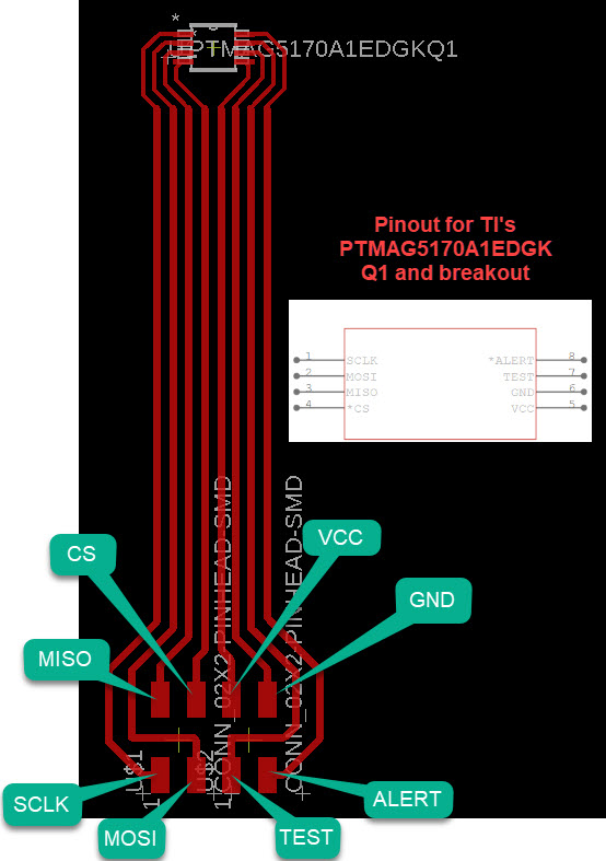
I did some searching for a good hall effect sensor for my final project and settled on a new (still in development) IC from TI called the PTMAG5170A1EDGKQ1. It is relatively cheap at $2.50 for single quantity, talks over SPI which is one of the faster + more reliable + simpler to implement protocols used for this sort of sensor. It also boasts +/- 2% sensitivity error + can support 3 ranges +/- 25, 50 and 100 mT sensing ranges, which can be switched in software. Lastly the sensor has on-board current compensation and reporting + does all of its own filtering which could lead to an ultimately cheaper microcontroller. TI also makes the TMAG5170A2-Q1 (although I couldn’t find it for sale on their website) which supports +/- 133, 200, and 300 mT ranges, so it would be neat to have an infrastructure of different “wands” for the teslameter. TI has really excellent whitepapers for both.
On the downside the PTMAG5170A1EDGKQ1 is still in development, and there are some sort of disconcerting questions on TI’s forum. It also only comes in a VSSOP package, which I had to narrow the pads for significantly to machine with a 1/64” end mill. Fortunately this seemed to work out fine in practice (also a good lesson learned in not being afraid to jump in and edit footprints to make them more machinable). I also looked at some chips from Melexis (more expensive) and Allegro (only support I2C) that have been around for a while and accomplish similar things, but opted for TI on account of the caveats in parenthesis.
I quickly drew up, milled, and soldered another PCB for the end effector as shown in the picture below. It would be nice to
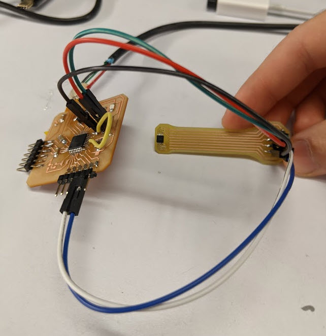
More to come later as my 3v3 rail mysteriously turned into a 4.45V rail while debugging SPI.
https://e2e.ti.com/support/sensors/f/1023/t/937812 https://e2e.ti.com/support/sensors/f/1023/t/938678