For week 10 our task was to program an output device to do something.
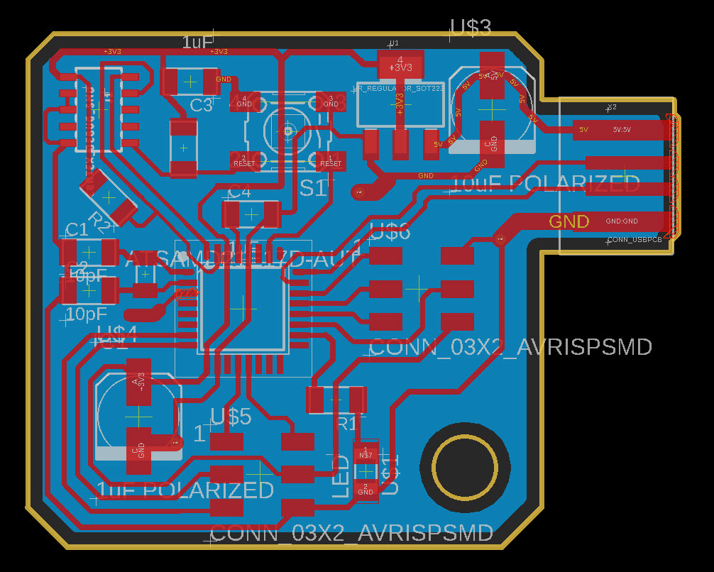
I opted to drive (and subsequently build) a stepper motor which is something that I am particularly interested in for my research. First I designed a new board around the SAMD21, this time using what I learned last week and Jake’s refences here, which helped improve my Eagle best-practices. New highlights are the use of a proper JTAG connector, a reset switch (that also gets used as a jumper and prevents needing a dedicated via / 2 layer board). There’s a ground plane on the back and 3 riveted vias, which is a workflow I really like for designing boards I will make in house. This time I broke out all of the dedicated SPI ports + a chip select on one header with power and ground. Getting these boards CAD’d up and machined is fortunately getting much faster now that we are a couple of boards in! To program I followed this tutorial from Adafruit to upload a trinket bootloader.
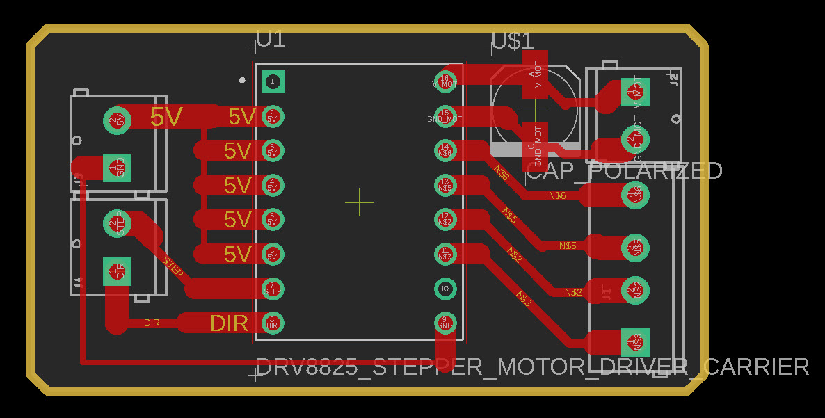
For the stepper driver, I opted to use a DRV8825 from Pololu because it was the first thing I was able to find when digging around the lab late on a weekend. In aggressive applications, stepper drivers are borderline considered consumables (they are easy to accidently blow up), and so they typically have male headers because they need to be hot-swappable. These were too tempting to quickly prototype with a breadboard, and so I very quickly put one together using the Pololu reference provided in the link above. In reality I should have put female headers on my SAMD21 board, but I did these things asynchronously + was trying to keep the SAMD21 board as boilerplate-y as possible… It would have been nice to have pre-emptiely put everything on one board, but this way I could bypass the painful process of soldering everything up again. The DRV8825 has 3 pins that can be pulled up to select a range of microstepping between full to 1/32. For the board I designed I pulled them all high, but left the trace thin enough to be cut.
You may, errr, notice that I have soldered the driver to the opposite side of the board as all of the screw terminals… That was because I soldered the headers onto the driver in the wrong orientation, and to avoid flipping them around I just reversed the driver (which wound up being more work considering the press fit through the holes was too tight and I wound up barely getting enough metal to create solder bridges through). Oh well, that was a good lesson in sunk cost fallacy.
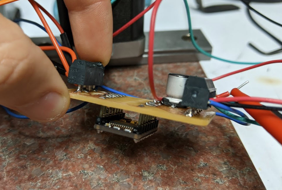
With the boards made I wrote a short script in Arduino and got an off the shelf bipolar stepper turning via standard step and direction signals.
  int dirPin = A3;
  int stepPin = A4;
  int dir = 0;

  void setup() {
    pinMode(dirPin, OUTPUT);
    pinMode(stepPin, OUTPUT);
  }

  void loop() {
    for (int i = 0; i <= 200; i++) // step in 1 direction 100 times (with 1/32nd microstepping this means 6.25 full steps)
    {
      digitalWrite(stepPin, HIGH);   // step pin high
      delay(1);                      // just looking for a rising edge so 1 ms is fine
      digitalWrite(stepPin, LOW);    // turn step pin off after 1 ms
      delay(10);                     // this delay determines our speed
    }
    dir = !dir;                      // boolean flip to change direction below
    digitalWrite(dirPin, dir);
  }
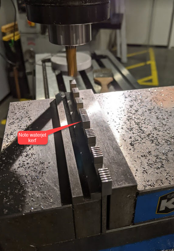
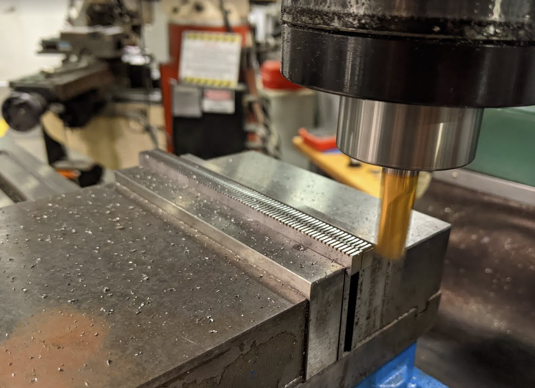
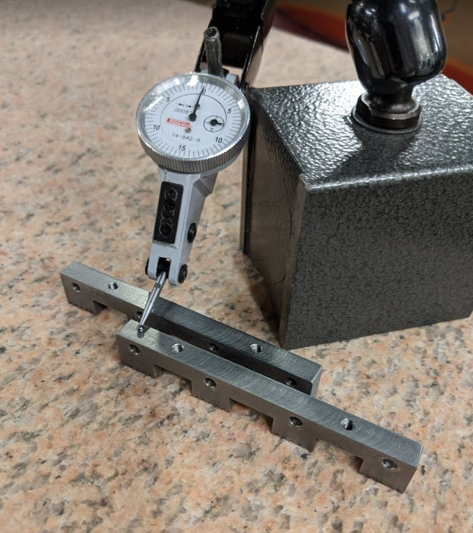
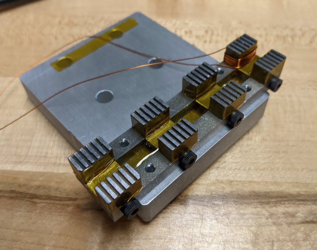
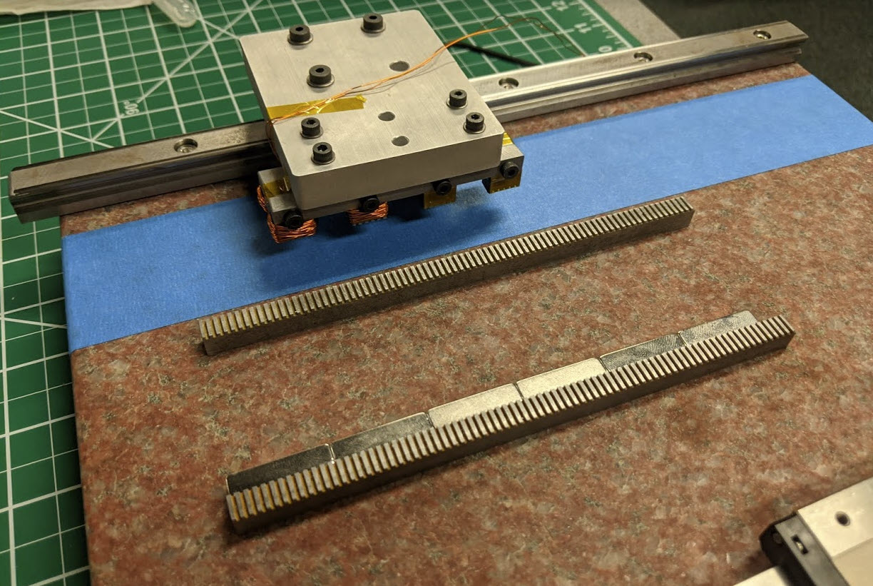
So this will be a bit of a tangent but I set out at the start of the week to CAD and build a linear stepper that I have wanted to make for a while now. From my understanding, it’s the closest approximation of a typical rotary bipolar hybrid stepper motor in a linear incarnation. Unfortunately it’s been creating very little holding force, and I am not 100% sure if it’s because of a design error (most likely) or a manufacturing error. There are 100 turns / phase and I am able to push 3A for short periods where I feel only the slightest bit of cogging while manually moving the forcer. I am able to hold a ~200um air gap, over 1mm pole pitch, and all of the steel was waterjet out of 1020 low carbon with reasonable accuracy. If I use 6.35x6.35 magnets like the ones shown in the photos below I definitely appear to be saturating the 1020 which I think might be a big part of my problem. Below are some shots of the machining process (the waterjetting was relatively self-explanatory) and inspecting process. I was able to get both pairs of forcer and stator to within 12.5um flatness and co-planarity on the CBA shop’s Trak, which is much nicer mill than what I am used to.
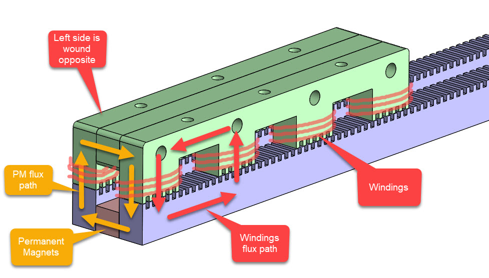
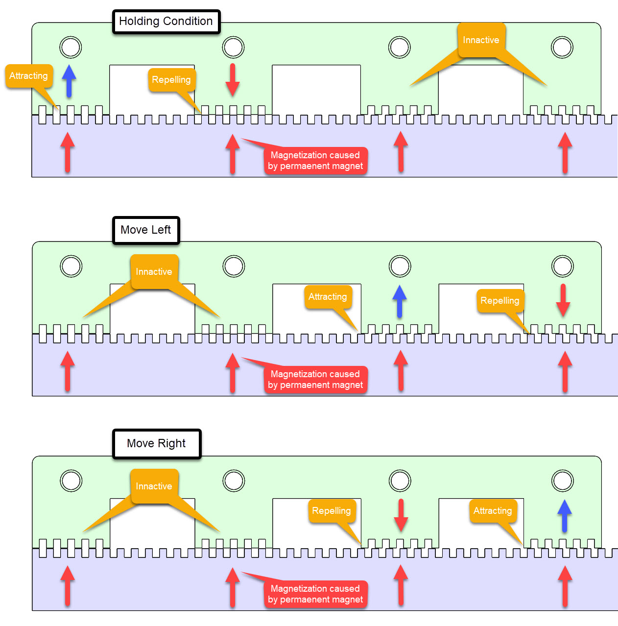
If you’re curious about how this thing is supposed to work then check out the photos below. I am not 100% sure about the two seprate flux paths idea. Every time I work on a motor design project I walk away from it with 2x more questions that when I started.
I spent a while trying to figure out how I should mount the stator to the surface plate. In the first photo I was trying the painter’s tape + CA method as per holding down parts on a mill, but after some chiding from Chris in our lab I just went and clamped them which worked nicely. The yoking effect of the two pieces of steel creates a very strong magnet that makes it difficult to maneuver the forcer over, but in the end I found a decent workflow considering I assembled and disassembled the thing ~10 times, and rewound it once (the windings were shorting through the layer of kapton tape wrapped around the forcer poles, and I was measuring ~5 ohms from one end of a winding to the steel itself). After that I added some red insulating varnish which I think is a better choice that the kapton. Lastly below is a video of it imperceivably vibrating, but not achieving full steps (you can hear it commutating if your turn the volume up).
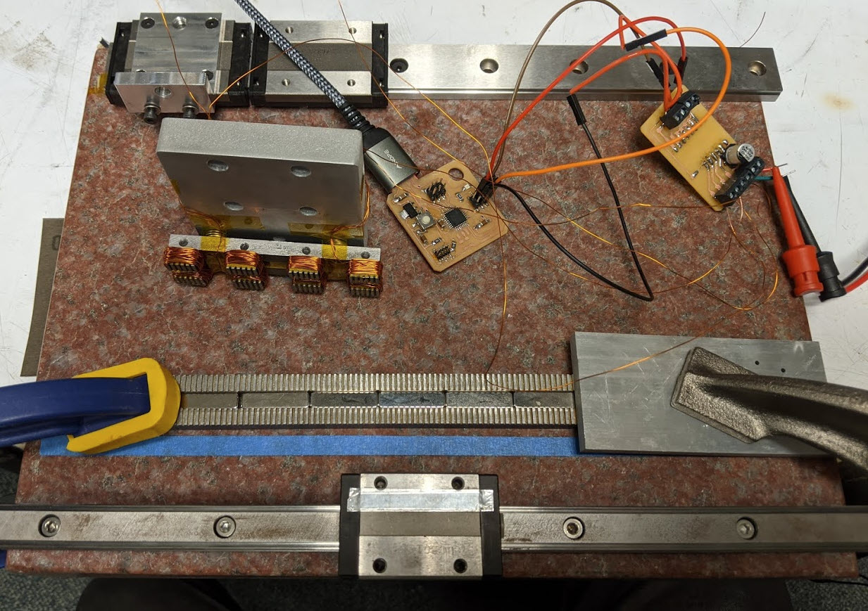
I’ve sent emails to the motor-inclined people I know, but if you have any ideas definitely get in touch!