Input Devices
This week was all about taking some sort of sensor or input device and getting it to talk to our boards. There are a variety of sensors that can measure all sorts of stuff. Many of them come in convenient packages that can go right on our circuit boards. So, building upon the skills we've developed the past few weeks in designing, milling, soldering, and programming circuits, we were able to get going!
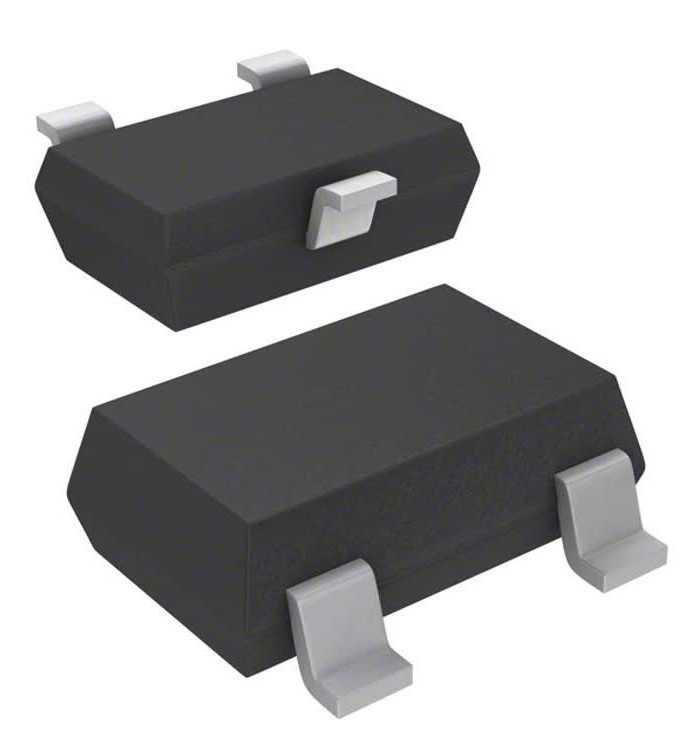
My sensor of choice this week was the Hall-effect sensor, which can measure the magnitude of a magnetic field. I'm thinking of using a few of these sensors in my final project to detect which block is placed into the sensor so that the message corresponding to that block can be played back. You can check out my Final Project page for more info on that.
First thing, I needed to design my circuit board. I used Neil's hello.mag.45 board (his hello.mag.t412 board wasn't completed at that point) as an example (found under the "magnetic field" section on this page). The Hall-effect sensor package wasn't actually in the class "fab" library, but I found one that worked.
I had some issues with milling, mainly because my best engraving bit got a little chipped at the top (I'll detail all of my milling issues in a little bit). However, I was able to get the board milled alright. Unfortunately, I then realized that I had forgotten to connect the FTDI VCC pin to the rest of the VCC traces, so that wouldn't work. I fixed that, played a bit with the outline cut, then milled again.
To add to some of the milling issues, I didn't catch that there were going to be two traces connected in my toolpath due to the spacing between pads being too small for the diameter of the endmill, but luckily I was able to just manually cut the traces with a box cutter. After checking to make sure the pads really were isolated with the multimeter, I was good to go.
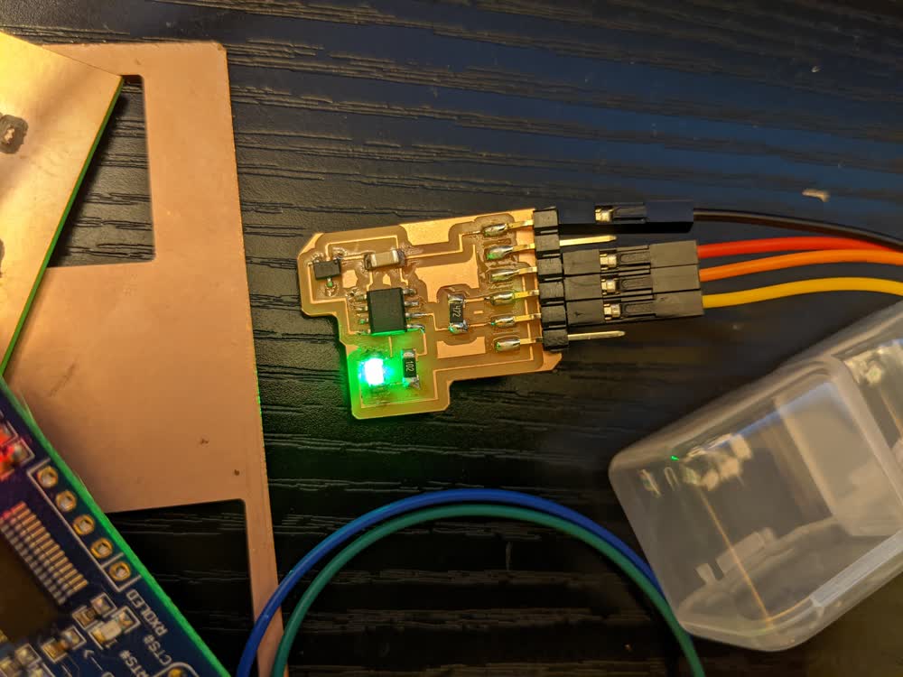
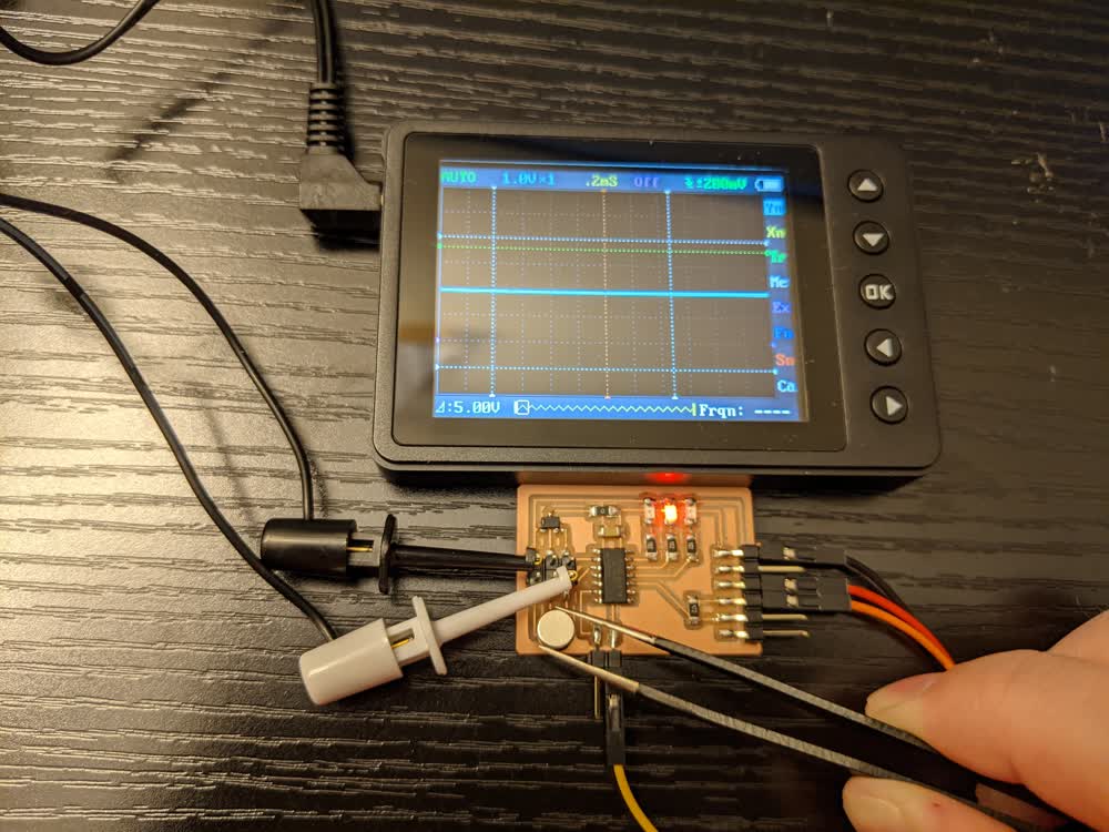
This one worked out really well! I got it soldered and programmed successfully. I first just made sure I could program it my getting the LED to blink (the green LEDs in our kits are much brighter than the red ones). Then, I started trying to read out the values of the magnetic sensor. It took me a while to figure out how to tell if it was working (because I did not design with easy testing in mind), but I finally proved that I got it working correctly by doing two things: 1) after reading the sensor's value, I divided that value by 100, and had the LED blink that many times, then pause before reading the value again, and 2) I was able to get my pocket oscilloscope connected to ground and then touching the Hall-effect sensor's output pin, and could see the voltage registering there. When I brought a magnet close to the sensor, I could see the LED change how many times it blinked, and I could also see the o-scope's voltage reading rise and fall.
It was a little awkward to try to hold a bunch of stuff in one hand while moving the magnet/board with the other hand, so I tried soldering a wire to the board so that I could connect the probe to it, and that did not work very well. In fact, it ripped up one of the traces. I knew I needed to make things easier on myself to really be able to test and play with the sensor, so I redesigned the board. It was nice to visually see that it was working, though!
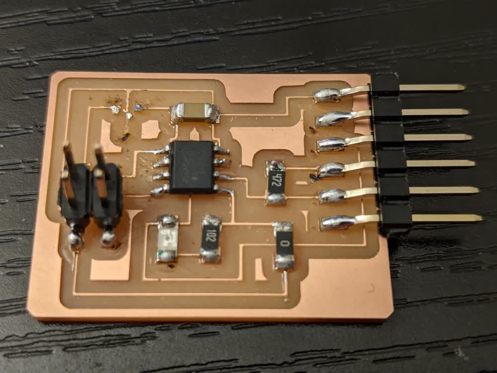
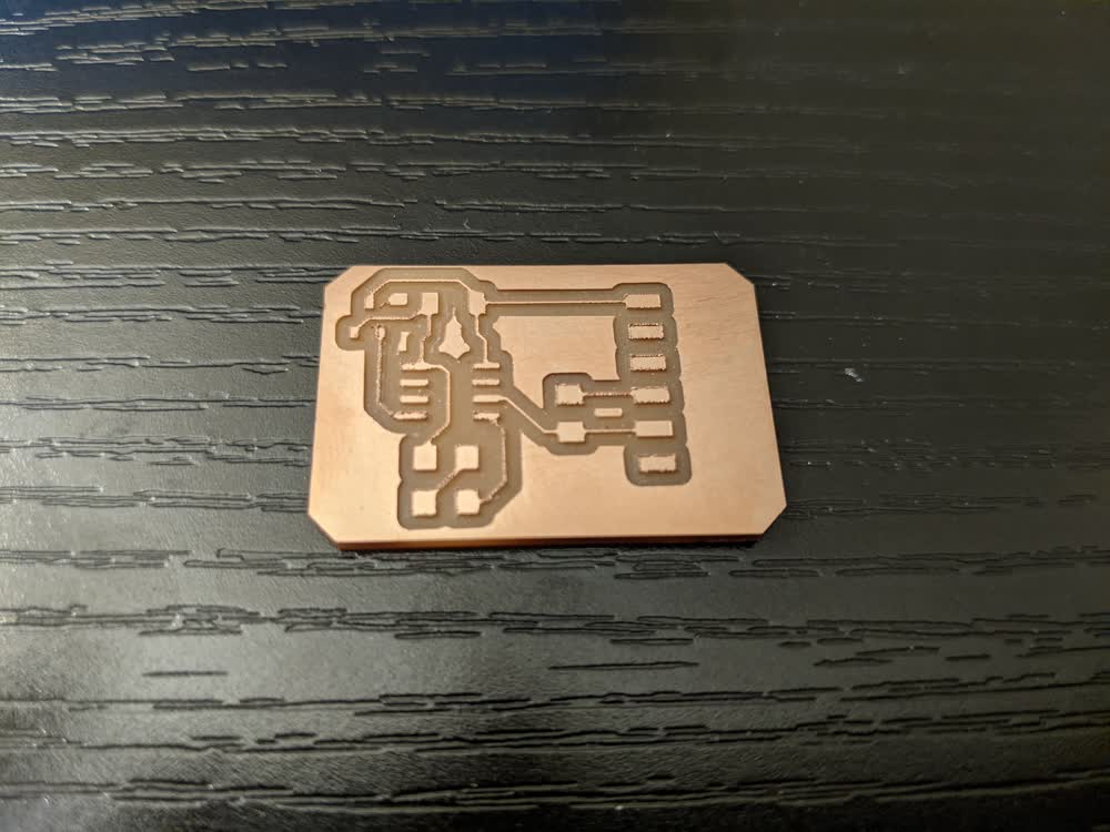
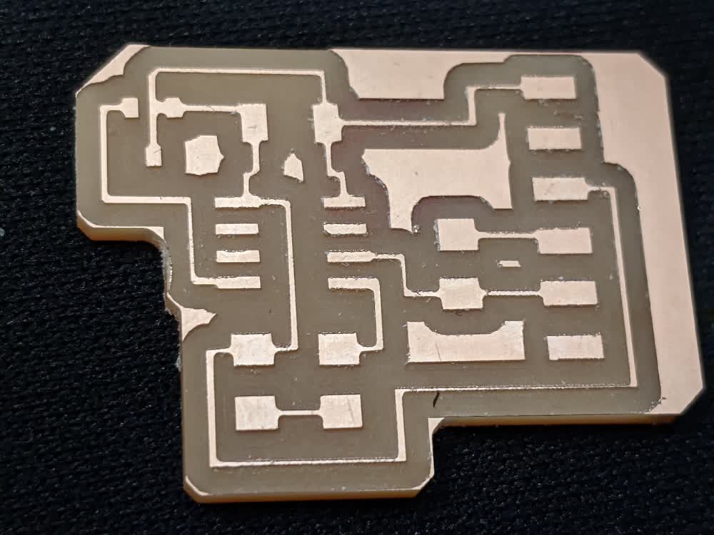
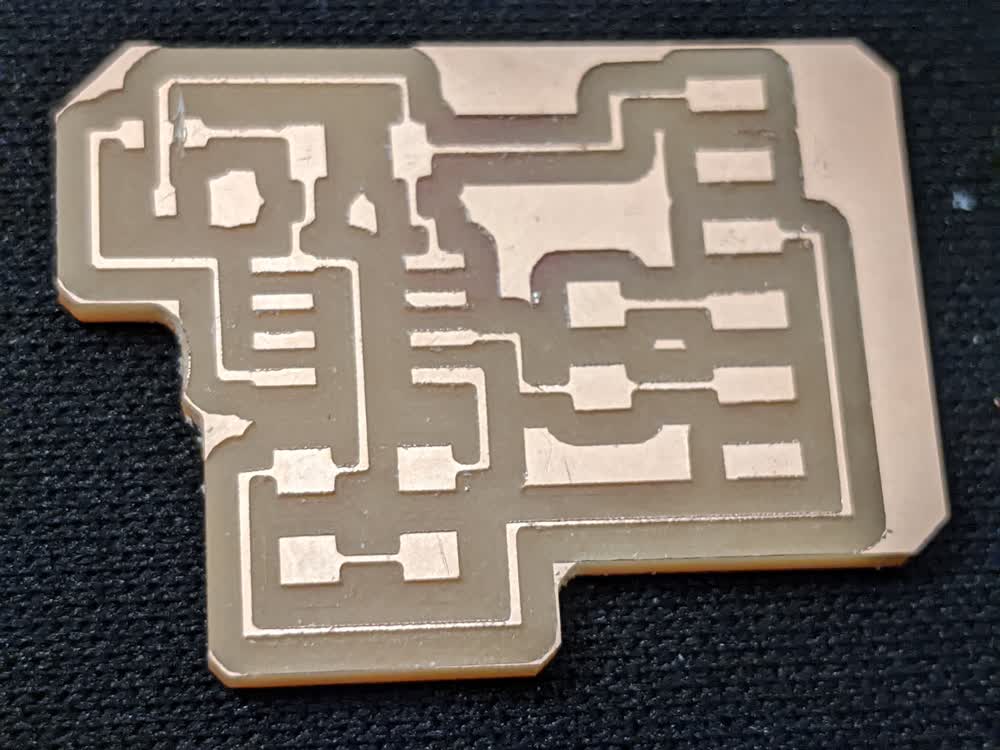
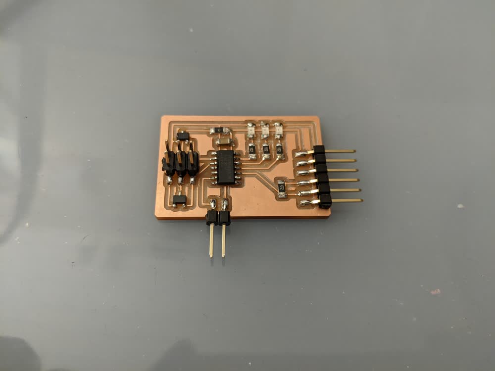
Here is the redesigned board. Note that it is missing the Hall-effect sensor in this picture because I ended up doing one more redesign that required two of the sensors, and we were only given two to begin with, and I didn't take a picture before I removed the sensor, unfortunately. However, this board brought some major successes! It was a bit hard to design because I couldn't figure out the best way to route everything. No matter what I did, it seemed, there was always a trace that needed to cross another one to connect to the proper pads. But that's when I realized the 0Ω resistor trick! You can just throw in a 0Ω resistor into your schematic, which itself just acts like a wire, but it lets you hop over traces when routing. Super convenient!
Anyway, I was able to test a lot better with this board because I had added the 02x02 pin header connector so that I had something to clip the o-scope probes to while testing. I played around with some things, but this is when I realized that I still hadn't figured out how to send data from the sensor to the terminal through the serial connection. I tried a few different things, including swapping the Tx and Rx cables after programming it, but to no avail. I decided to not worry about the actual sensor for the time being and just see if I could get the hello.t412.echo program to run on my board (found on this page). After talking to Andres, I played around with it some more and finally realized what was wrong. The hello.t412.echo board requires the use of the UPDI to FTDI board, but I thought I had designed around the need of that by adding the 4.7kΩ resistor between the UPDI pin of the ATtiny and the Tx/Rx lines of the FTDI connector. This is purely for programming the device, and is not used for serial communication after programming. To actually talk with the board, you need to have the Tx/Rx cables connected from the serial adapter to the Tx/Rx pins on the microcontroller. For the ATtiny412, this is typically pins 2 and 3 (PA6 and PA7), but by using the line "Serial.swap(1);" in your Arduino code, you can use the alternative Tx/Rx pins, which are pins 4 and 5 (PA1 and PA2). Luckily, I had broken out pins PA1 and PA2 to my pin header connector, so I was able to get everything connected properly, and finally saw my board successfully echoing what I was typing.
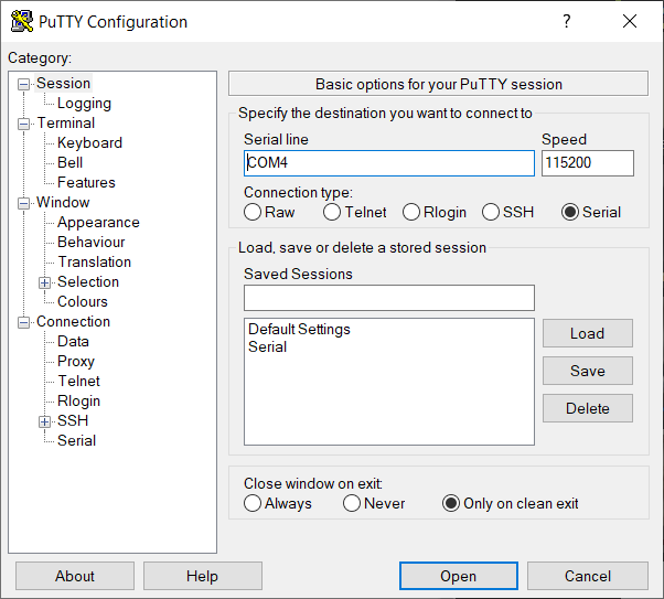
One note on serial terminals: If you are using Windows like me, the Arduino serial monitor terminal works, but has a bit of a weird interface when it comes to sending data to the board. Per Zach's suggestion, I downloaded PuTTY, and was able to get that working much more smoothly by clicking on "Serial" for "Connection type", inputting "COM4" into "Serial line" and my baud rate of "115200" in "Speed". I clicked open, saw a blank terminal, then typed a letter, and it echoed right back to me! It is a little obnoxious to have to close/reopen the terminal and switch the Tx/Rx cables every time you go between programming/running, but I don't think there's really an easier way to do it.
Unfortunately, because I didn't realize that there were actual Tx/Rx pins on the microcontroller, and instead was just routing through the UPDI pin, I couldn't get my sensor values to be sent over the terminal properly. It was time for one final redesign, but I did a quick sanity check before that. I told the microcontroller to use the typical Tx/Rx pins (PA6 and PA7), then held my o-scope probe on PA6 and had the board send the magnetic value over serial. I could see a set of distinct pulses every time it read and sent, so I knew that it was working, but I just needed a better way to access it.
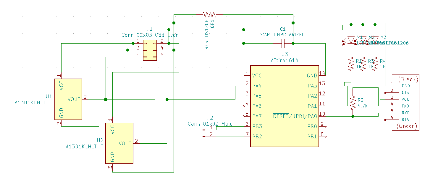
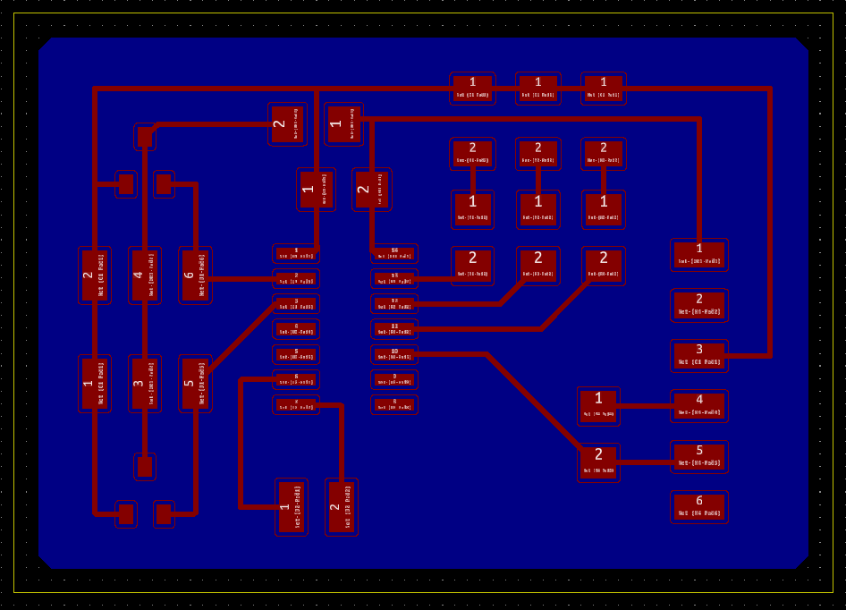
Behold, my final board design! Please ignore how messy the schematic is, I'm still learning how to make the schematics more beautiful and easy to read, but I know what's going on, so it works for me. Routing traces wasn't too bad either, especially since I realized that having unnecessary connections and pin headers is better than not having the ones you need. So, it might seem a little overboard, but I have not run into any problems or limitations trying to test it. As you can see, there are two Hall-effect sensors and three LEDs in the design. I wanted to have one LED to signify that the board was programmed and working, and the other two to map directly to one sensor or the other.
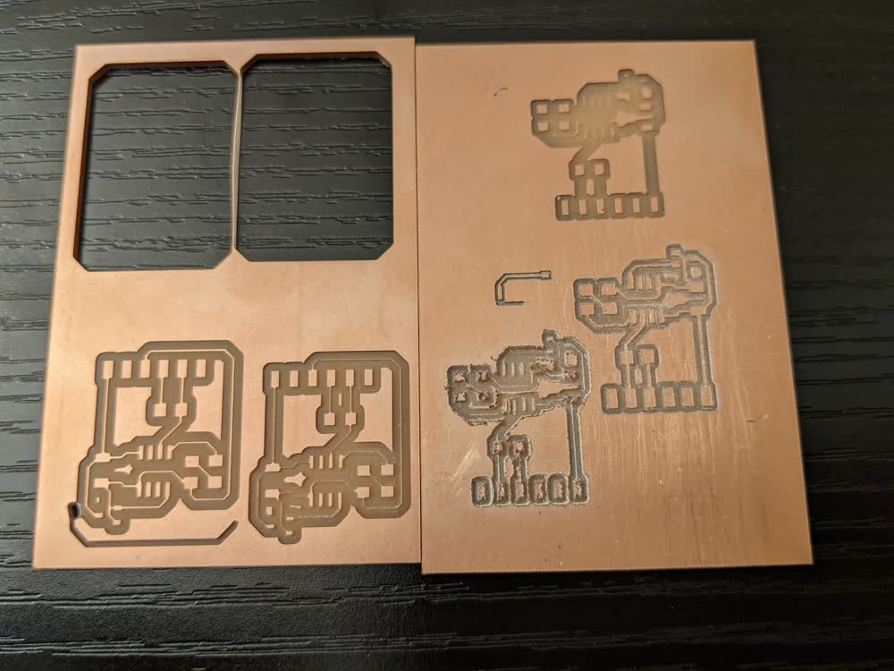
I suppose now is a good time to get to my anecdote about milling troubles. I have never had much success with any of my bits except for one particular engraving bit. All the others don't cut super cleanly and cause a lot of burring on the edges. However, that one bit that has worked so well for me got chipped. There were some changes to mods that I forgot to double check when toolpathing, so one of my cuts was set to millimeters instead of inches for the format and minutes instead of seconds for the rate units. This caused the cut to go extremely fast, and it chipped the tip of the engraving bit. With my favorite bit no longer as thin as it used to be, I had to dial in the true diameter of all of my end mills to get the proper spacing between pads and trace widths, all while battling burring on the edges of the cuts. My machine was also having a bit of an issue with vibration on the X-axis. It wasn't terrible, but noticably worse than it normally is. So, milling boards took a lot longer this week, but I finally was able to dial in the correct diameter and found another endmill that works well. I also set my machine on the floor, rather than my desk, to mitigate the vibrations. It's awkward to lay on the floor with my keyboard dangling down, but it works!
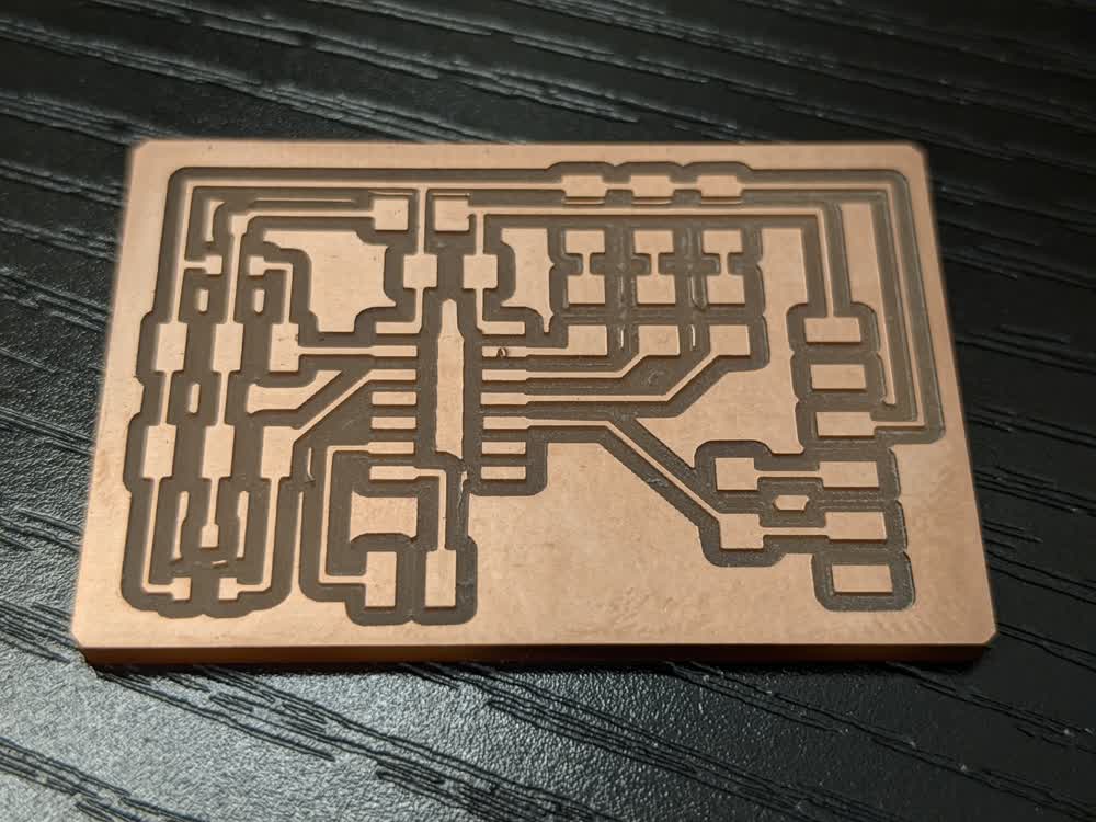
Everything was finally ready to go! Milling and soldering went well, and it was time to program! Oh, I forgot to mention that I switched to the ATtiny1614 for this board just to give some more space and pins to work with to make my life easier haha. First, I made sure everything was working by blinking the LEDs and echoing through the serial terminal. Then it was time to finally see the magnetic value readings in real time through the terminal instead of on the o-scope!
It all finally worked, yay!!! One LED constantly flashes showing that the board is powered and running, both sensor values are constantly being flashed to the serial terminal, and if the values go above a certain threshold, that sensor's corresponding LED will light up. There are still some major improvements that can be made to this code, such as the sampling that Neil does in his "hello.mag" code, and I am just using basic Arduino functions instead of the faster and lower-level AVR commands, but it's in a good working state, so I am satisfied. I also can play around with the polarity of the magnets and decide if I want to recognize the magnet on both polarities, namely, when the value goes both above and below a certain threshold, not just one or the other. Now I can more effectively plan exactly how I'm going to get the reading portion of my final project implemented! Excited to continue on with that, as well as move on to the next steps!
Here are the files I generated for this week:
- input_mag.zip - All KiCad Files in a ZIP Folder
- input_mag-F_Cu.svg - Traces SVG File
- input_mag-B_Fab.svg - Outline SVG File
- input_mag.t1614.ino - Arduino INO File