Final Project
Skip Down To:
- Final Project Presentation
- Log #01: Initial Design
- Log #02: Magnetic Sensor Testing
- Log #03: 3D Printed Blocks
- Log #04: Laser Cut Structure
- Log #05: Block Holders and Buttons
- Log #06: Vinyl Cut Face Decals
- Log #07: PCB Design, Milling, and Soldering
- Log #08: Programming
- Next Steps
Final Project Presentation
I created a prototype for an asynchronous voice message device that does not require a screen and can be operated by my toddler. The inspiration for this device was to find a way to allow my almost-three-year-old daughter send and receive messages with some family back home without the need to use a smartphone or similar device. Bringing this whole device from the early design stages to the physical assembly and finally the programming and testing was quite challenging, but very rewarding. I did not accomplish everything I had initially set out to to do, but I am satisfied with what I was able to do and have a good plan to improve this project further in the future.
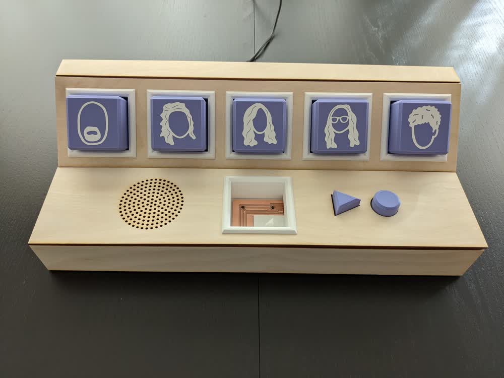
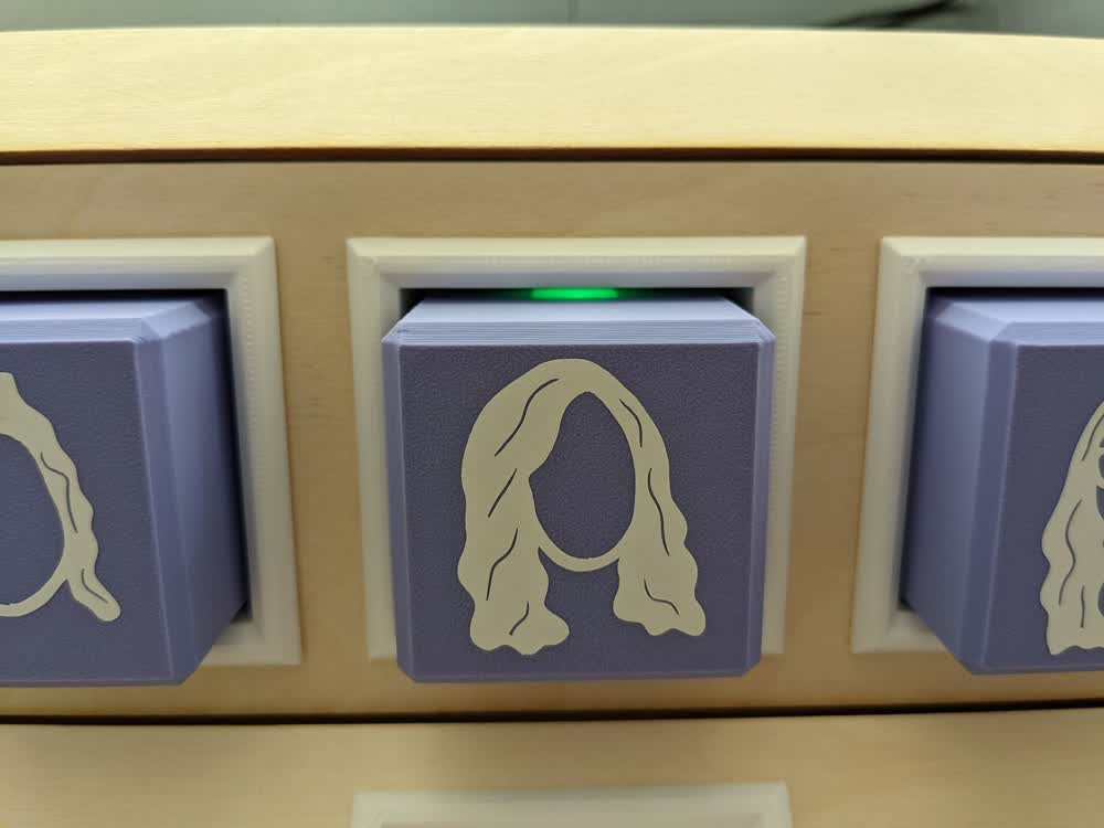
First, to demonstrate the behavior of the reader device, I show that each block can be successfully read by having its coressponding LED light up. I then show how by using the play and record buttons, the corresponding LED will turn on and off depending if the incoming recording has been played back or not. This functionality will make more sense when the clone of this device is implemented and networked together.
The physical design process was a lot of fun, and I learned a lot. While I was able to get everything assembled and together in the end, there are a lot of design tricks that I need to continue to improve upon and implement in order to make assembly and stability of the structure better.
Aside from the time crunch I hit to get everything done, and subsequently not having as much time as I would have liked to iterate on everything, the physical design was done and it was time to get programming.
The microcontroller used is an ATtiny3216, which reads the input from the three Hall-effect sensors (which detect the magnets on the bottoms of the 3D printed blocks), as well as the push buttons (connected to the 3D printed play and record icon buttons). It then controls the LEDs corresponding to each block and its holder, as well as sends the data out to a Raspberry Pi Zero W, which will then use that information to control the speaker/mic module I will implement in the future and upload/download voice messages over the internet between the two networked devices.
Log #01: Initial Design
Introduction
Welcome to my Final Project page. I want to make an Internet of Things connected voice recorder/playback device for my daughter to use as a long-distance asynchronous walkie-talkie with her grandparents and aunts and uncles without the need for a screen. Below is a detailed walkthrough of the development of the idea and project itself. The first portion is largely a rehash of the first week's worth of work I did in terms of fleshing out the initial idea, but will be followed by the work I accomplish in actually creating the device as I go along. I am enthusiastic about the project, and I am excited to see how it all goes.
Initial Concept Formation
Thinking about all of the various skills I am to learn this semester, one of the most intriguing is making our own electronics and IoT connected devices. I wanted to do something that focused on interacting with someone that was in a different house than you, even if they were across the country (or even the world). This was inspired by both the COVID-19 pandemic, as well as a previous class I took in interaction design. I came up with quite a few ideas, but only two stuck out. One was a smart chess board, enabling me to physically play a game of chess with someone else, but after seeing that it has been done before, I went with something a bit more unique and personal.
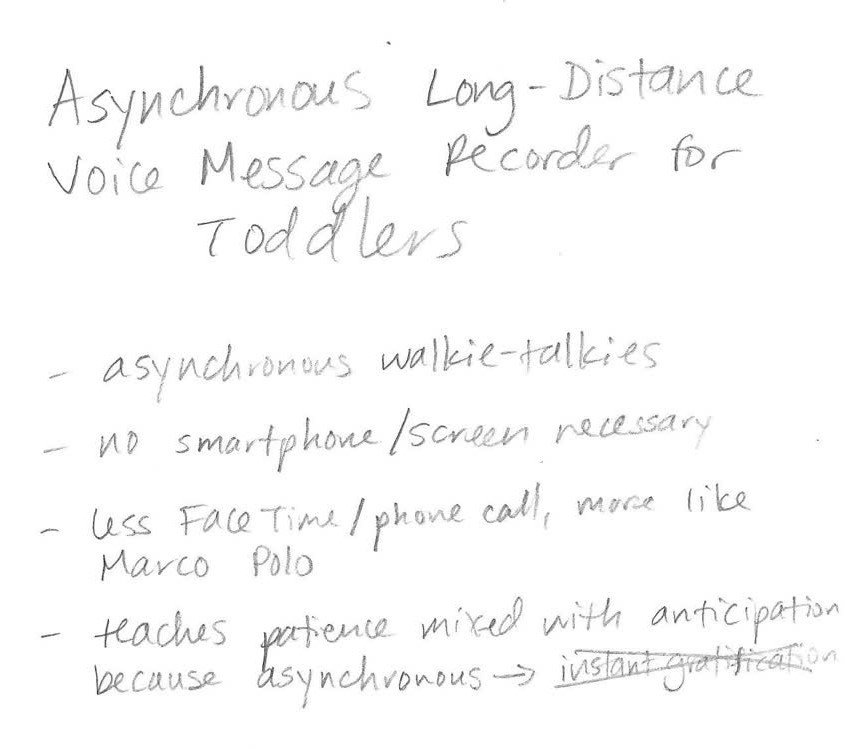
My idea is to make an asynchronous message recording and playback device designed to be used by my two-and-a-half-year-old daughter. It's basically like a long-distance walkie-talkie, but messages can be recorded and played back at the user's convenience. My daughter gets to talk to my family (her grandparents, aunts, and uncle) often on the phone or over voice chats, but they're not always available, and the last thing I need is a toddler demanding their own cell phone... There is an app that my wife uses (Marco Polo) to record asynchronous (and also sort of synchronous) video messages, but again, that requires a smartphone. I want to make something that is simple to operate and that doesn't have a screen. I think the asynchronous portion will also teach my daughter patience in that she won't get a response immediately, but can be excited throughout the day to periodically get a new message from someone (this also abides by the practical real-time communication limitations of such a device). So, with that idea in mind, let's sketch it out!
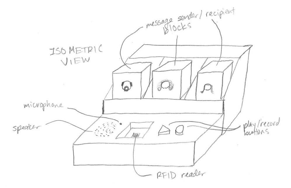
The aesthetic greatly resembles small children's toys with the block and slot design. I plan to have one block for every person she can send messages to, with an icon of their face on it. These blocks will have some sort of identifier embedded in them, such as an RFID tag, to allow them to be identified by the system. The blocks can be moved one at a time from their resting slot to the RFID reader slot, then a play or record button is pressed to play the message through the speaker, or record a message through the microphone, respectively.
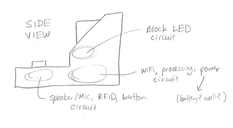
Looking from the side, you can see where I plan to embed the circuits to control the speaker, microphone, RFID reader, and buttons, the LEDs for the blocks, and the main brains of the system including the WiFi connnector, power, and processor. I will be sure to leave enough room for all of these components.
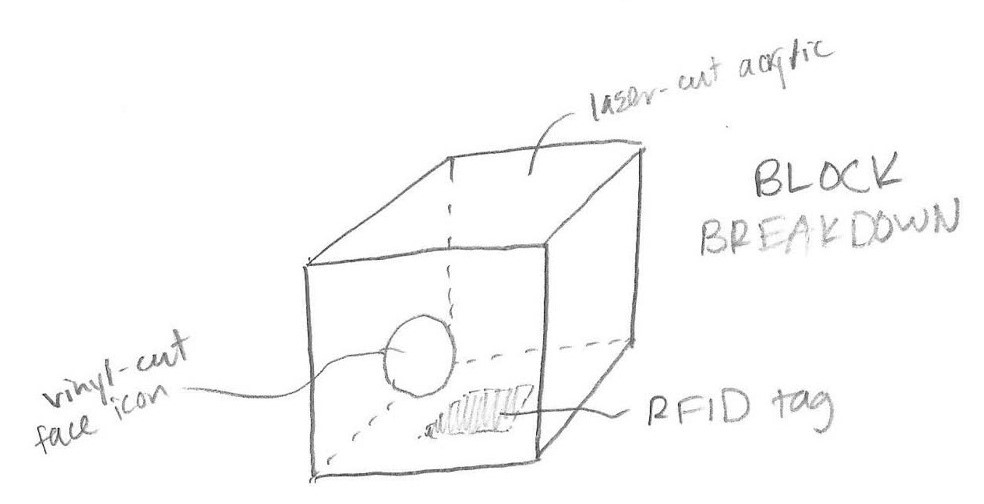
I'm thinking about making the blocks out of a white acrylic, excpet maybe making the bottom clear because 1) the LEDs will shine through better and 2) it would look awesome to see inside! The bottom will have an RFID tag embedded to it, and with my wife's artistic help, I'll vinyl cut a simplified icon of each family member's face to stick to the face of the block.
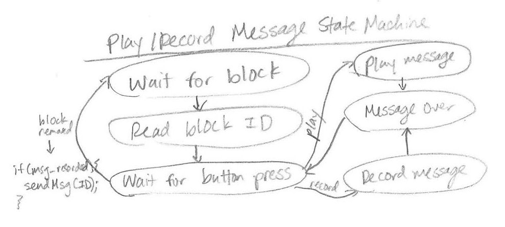
I know that I'll need some state machines driving the code for the system, so here is a first pass at figuring out how the system will work. The play/record system won't do anything until a block is placed in the reader (perhaps I'll have a contact switch in there to tell the system when to query the RFID tag). Once a block is placed, it will read the ID, then wait for either the play or record button to be pressed. If the play button is pressed, the latest message recorded by the person whose block is inserted will be played. If the record button is pressed, the microphone will turn on and record until either the button is let go or pressed a second time. Once the message is over, it will await another button press, or for the block to be removed. The newest recording will overwrite any existing messages. Once the block is removed, it waits for a block to be placed again. Any recorded message will then be processed and sent over the internet to the other device.
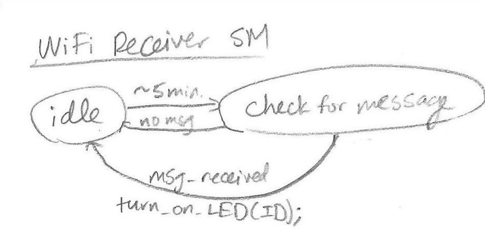
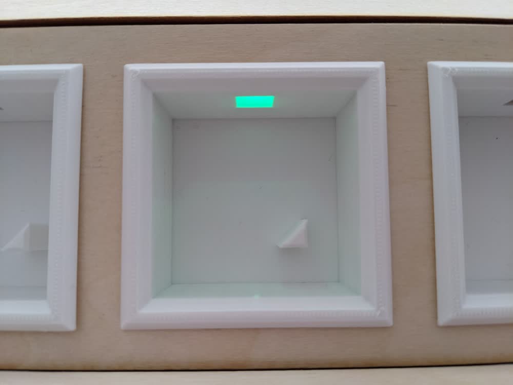
On top of sending messages once they've been recorded, the system needs to check for messages coming in from the other device. I don't want the device to use too much power and be constantly checking for new messages, so I'll have it check for messages every 5-10 minutes or so, depending on where that sweetspot is. If a new message that hasn't been played back yet is received, it will activate the LED in that block's slot to signify a new unopened message.
So, there's still a lot to flesh out with this project, but these are the basic ideas of what I want to make, and I have a pretty good idea of what materials/skills will be required to make it. The physical box and blocks will probably be made using laser-cut acrylic. I would like to make some soft silicone buttons using a 3D-printed model that I'll mold and cast. The smarts and the guts of the device will be made with various custom PCBs and electronics. Finally, I'll decorate it all with some nice vinyl-cut decals and I might even engrave something into the device. With all that in mind, it was time to design it with some CAD software!
Initial CAD Design
I'll be using Fusion 360 to model my project because I have the most experience with it out of all CAD programs, and it's very well documented online, so if there's ever anything I can't figure out, I can look it up pretty easily. Alfonso's recitation was very helpful in giving some more concrete examples on how to use parametric design to my advantage.
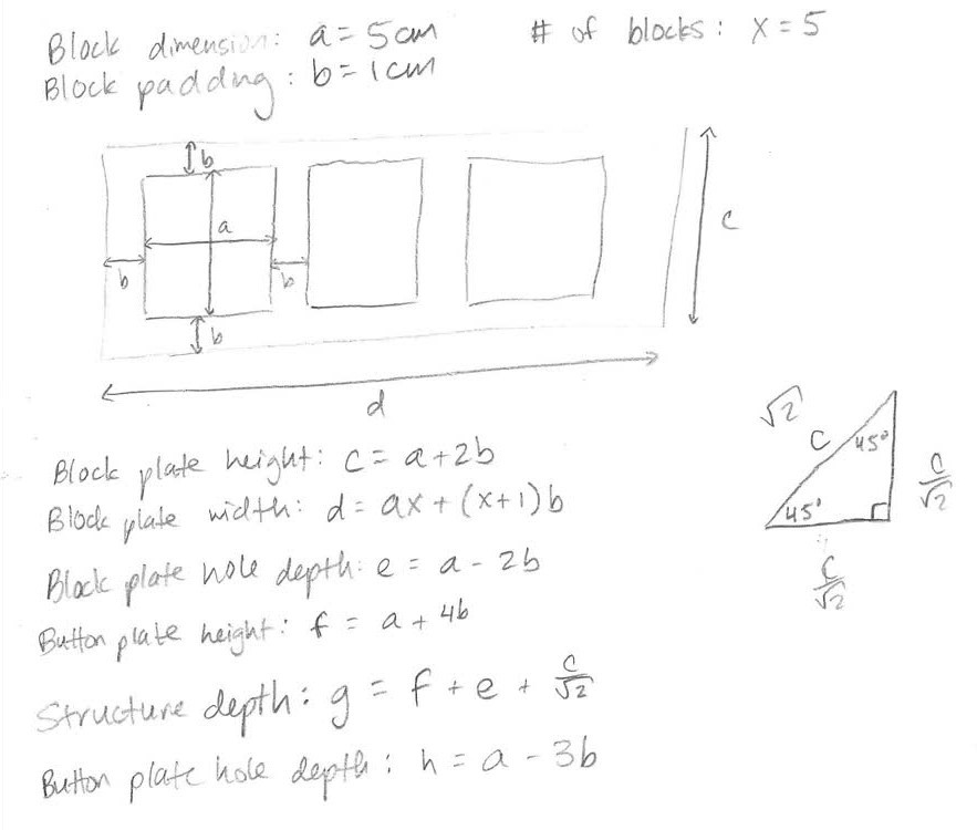
I played around a lot with different sizes and dimensions of the various parameters, but finally decided on some nice values, then used this little cheatsheet to help me fill out the design properly.
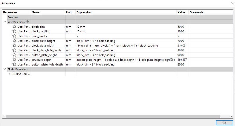
I spiraled quite a bit in developing these parameters because I wouldn't know that I needed a certain value or relationship saved, but it was still extremely easy and beneficial to keep updating as I went.
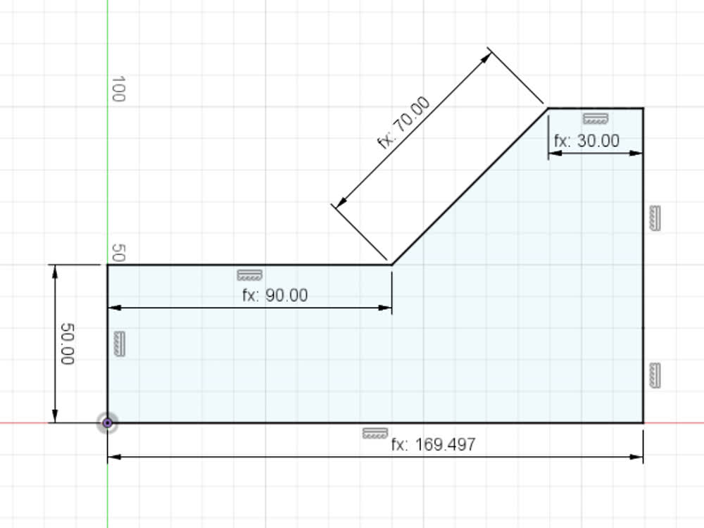
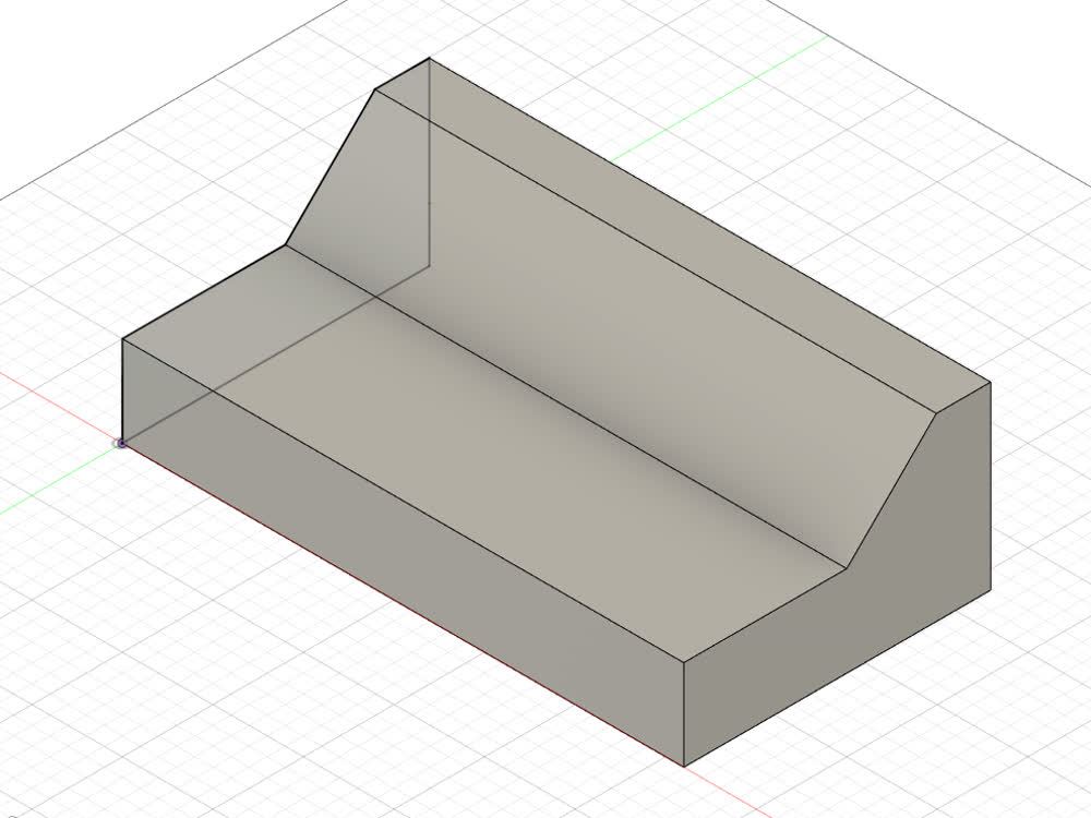
With all the math figured out, I made the side and extruded it.
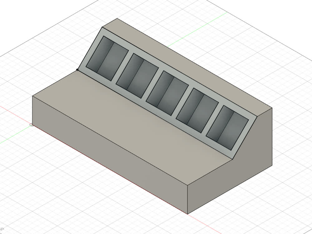
Then I cut in the slots for the blocks, making sure they would still be exposed slightly and easy to grab.
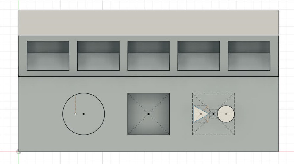
The reader cut-out was pretty straight-forward, then I added the two buttons as separate bodies. The circle on the left is a place-saver for the speaker hole-mesh I'll add in a moment.
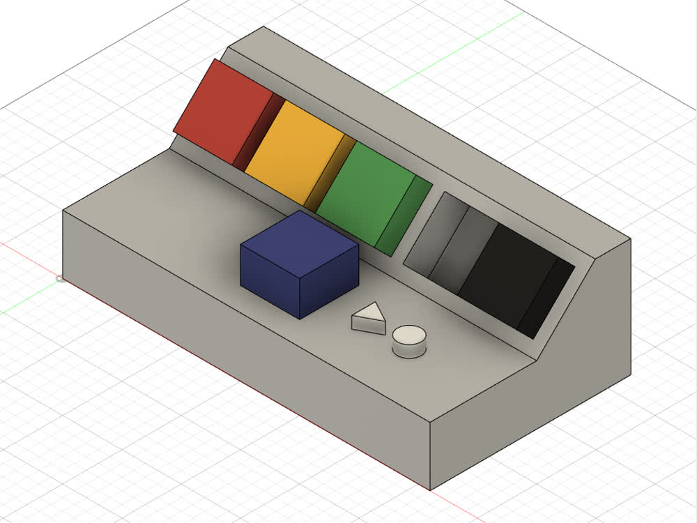
There will obviously be some changes that need to be made due to tolerances, but the blocks will rest in either their slots or in the reader.
I had some fun figuring out the math/design behind hole meshes for speakers. Rectangular and circular pattern tools saved the day! For future reference, starting at the center, each the number of holes (H) per ring (r) has the following relationship: H = 6(r-1) (very middle hole represents r = 1).
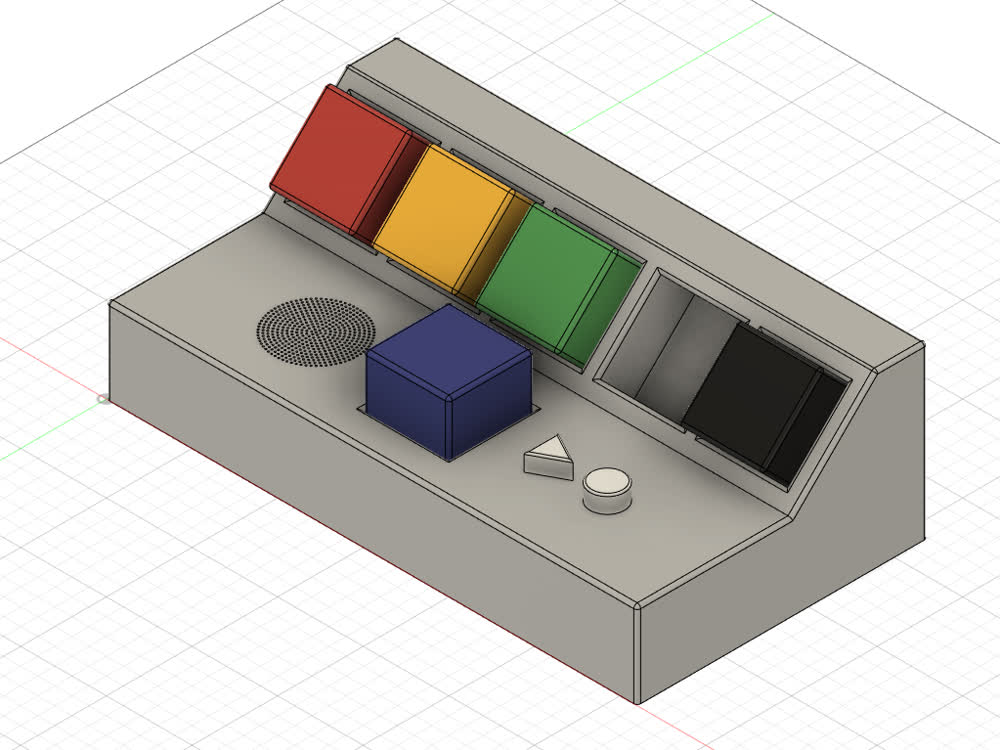
Finally, I filleted all the edges to give the whole thing a softer look, and now the initial design is finished! Rendering time!
Here's a quick attempt at animating the system in use.
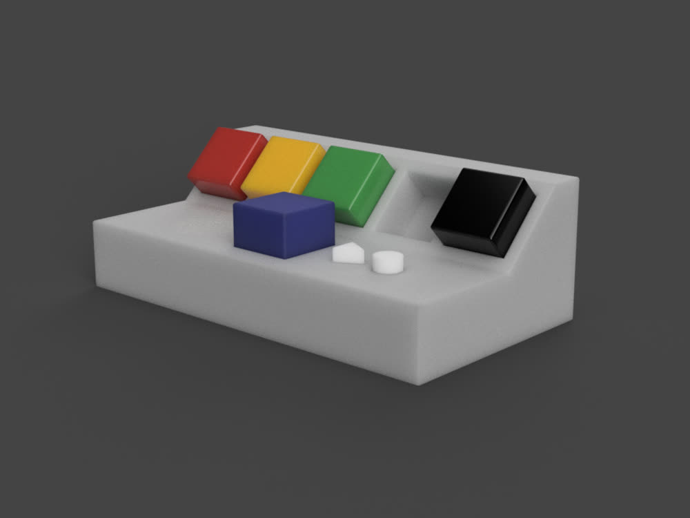
And there you have it! I can't wait to actually get to making this thing! The next step is to solidify the design of the shell and get getting and assembling the structure, while leaving plenty of room to fit the electronics inside.
Here are the files I generated for up to this point in the project:
- final_project.f3d - Final Project Model Fusion 360 File
- final_project.step - Final Project Model STEP File
Log #02: Magnetic Sensor Testing
Most of the following information can be found by visiting my Output Devices page, but I will detail it again below for convenience.
I needed to find something to use to determine which of the blocks were inserted into the reader so that the correct message could be played back or so that the recorded message could be sent to the correct person on the other end. Upon learning about Hall-effect sensors and how well they worked, I decided to test them out to see if they would work for my purposes.
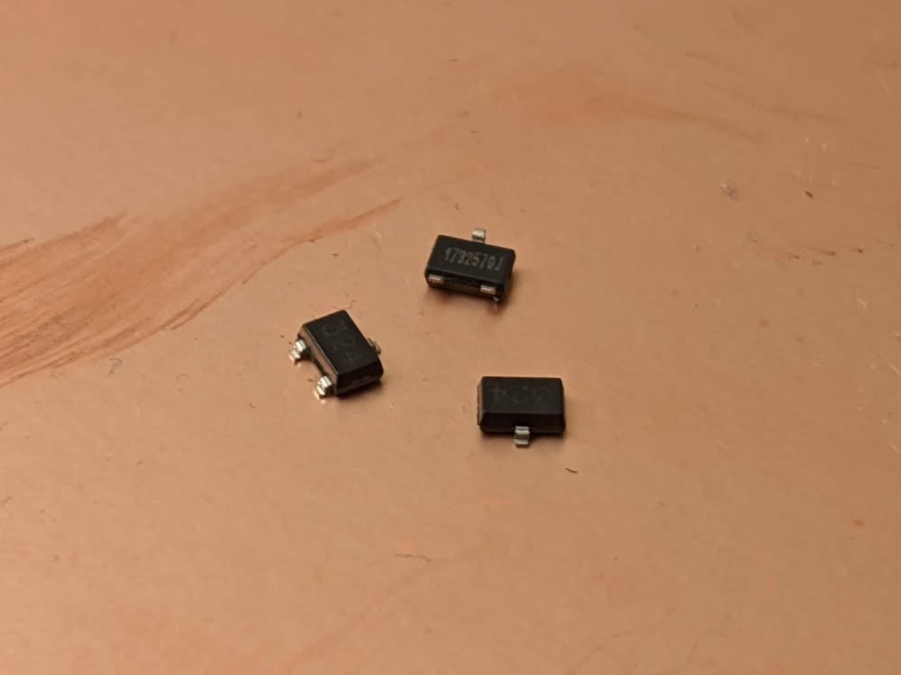
I am using these Hall-effect sensors. They're very cheap and work really reliably. All they need is power, ground, and an output line to send the data to a microcontroller.
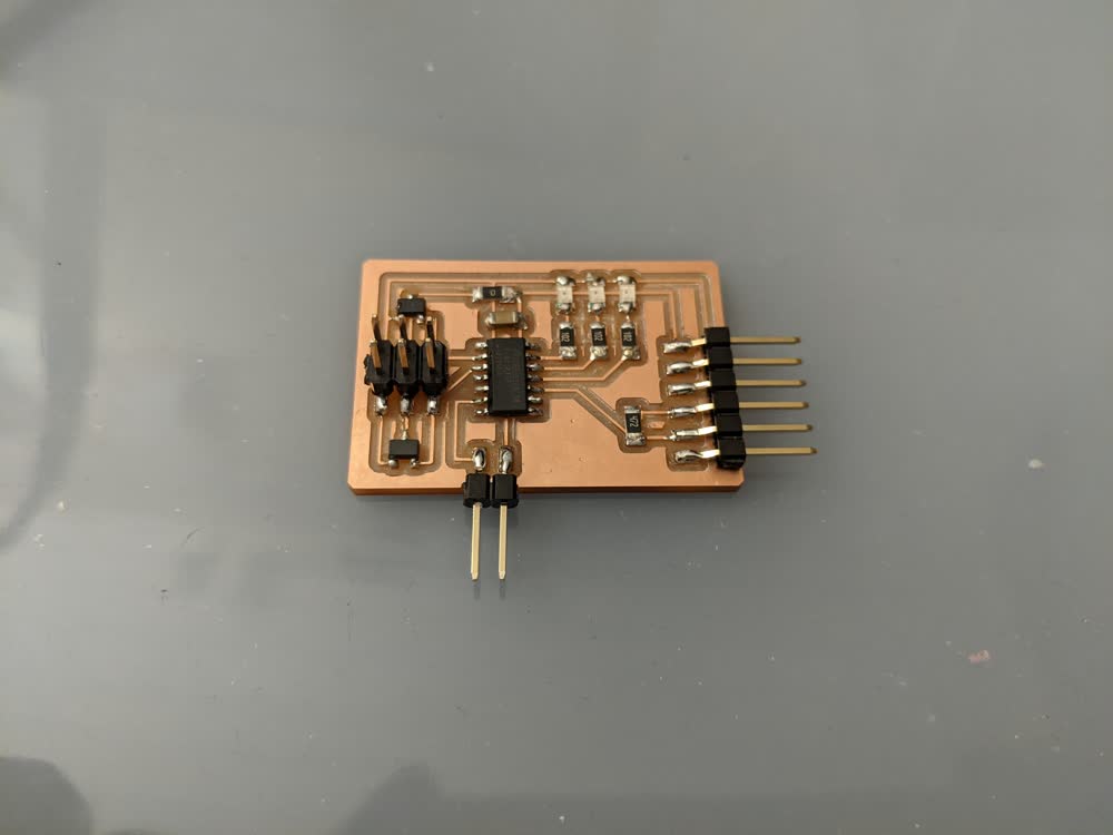
This is the board I designed to test the capabilities of the Hall-effect sensors. There are quite a few headers that I soldered for ease of testing, but essentially it's just two Hall-effect sensors feeding into an ATtiny1614 and three LEDs to react to the magnetic forces applied to the sensors.
To test the sensors, I first hooked up the oscilloscope to one of the sensors, and began moving a magnet near it. As I moved back and forth, I could see the output voltage level of the sensor rising and falling. When I flipped the magnet over, the voltage level continued to move, but in the opposite direction, showing that the sensors are sensitive to polarity. I also had the microcontroller sending out the values it was reading from the sensors so I could see the relative values in real-time. It appears that a value of about 500 is the base level, then with this particular magnet, will rise up to around 1000 or fall to near 0 depending on the direction the magnet is facing.
With all this in mind, I then utilized the LEDs on the board to do a bit of conditional testing. I had one LED light up when the magnet made one sensor clear a certain value threshold, then the same for the other LED and sensor. Finally, when I put a magnet close to each of the sensors at the same time, both LEDs would light up. Knowing this, I can move forward with my binary encoding scheme to differentiate the blocks.
I played a bit more with the sensors to determine how different parameters changed the output of the sensors, such as distance between sensor and magnet, which allowed me to get a good feel for the final design that I will make. I will definitely need to do a lot of fine-tuning still, but I have designed everything to allow for fine-tuning individual sensors and thresholds, so I have room to wiggle around.
Log #03: 3D Printed Blocks
Next up, knowing that the magnets and Hall-effect sensors would work to differentiate the blocks, I needed to design the actual blocks. I made an arbitrary binary encoding scheme so that each block would have magnets in different locations (no magnet being a logical 0 and magnet present meaning a logical 1), so that I could get up to eight different values. I only have five blocks that I'm working with, so that's more than enough.
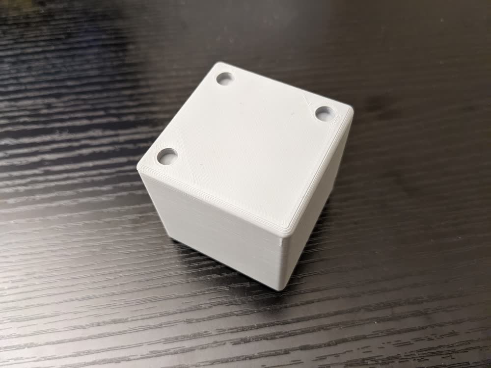
The first block that I printed was very simple. A small cube with three holes to insert the magnets. I filleted the edges to make it easier to hold and it seemed to work pretty well. However, I didn't love how the filleted edges came out with uneven layers due to the quickly varying overhang angle that such a geometry creates. Another issue with this design is that while it can't be read unless the correct face is inserted, there are still four different possibilities of readings that can come out depending on the rotation of the block.
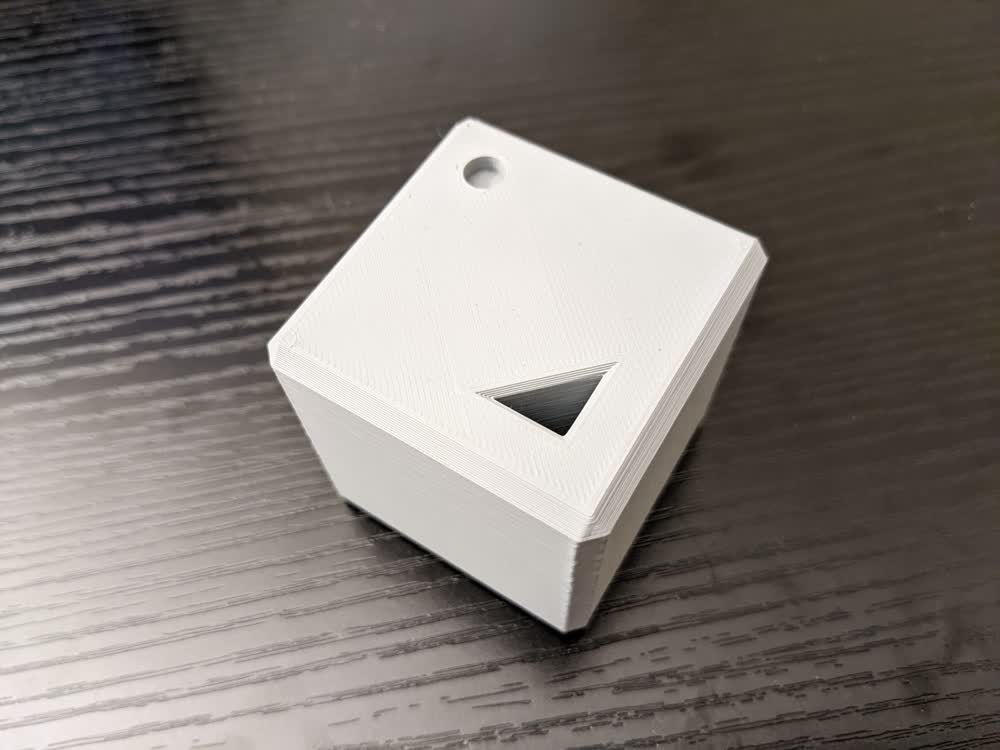
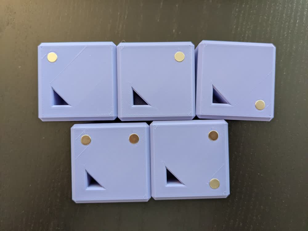
So, to fix those two issues, I designed the blocks to have chamfered edges instead of filleted edges, and I added a small triangle-shaped hole in the blocks that I will have a peg of some sort sticking up from the reader so that the blocks can only be properly inserted in a specific orientation.
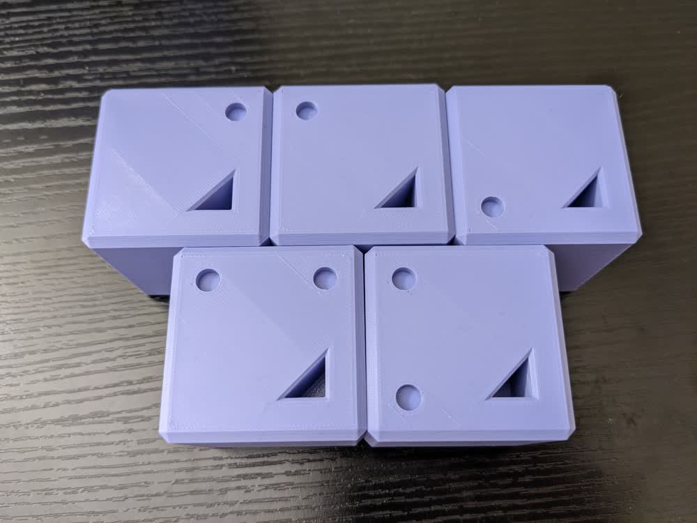
With that design in place and working, I went ahead and printed a full set. My daughter's favorite color is purple, so I opted for the lavender filament instead of the gray. I just need to secure the magnets into each of the holes (they fit nicely, but a bit of superglue should due the trick to secure them), then I can focus on the reader.
Log #04: Laser Cut Structure
I had already roughly design the structure that I would be using to house all of the electronics and other components, but I had to go in and make some adjustments based on the material that I was using and the tool I was using to cut it. I ended up going with laser cutting some simple 1/8" plywood because it just looks nice and was straightforward.
My wife helped me assemble the structure with some wood glue and some good patience, then it was on to the next step!
Log #05: Block Holders and Buttons
I now needed something for the blocks to rest in and be held by in the structure. I decided to 3D print these holders because it would be faster than trying to also make them out of wood, and the different colors were fun to add to the project.
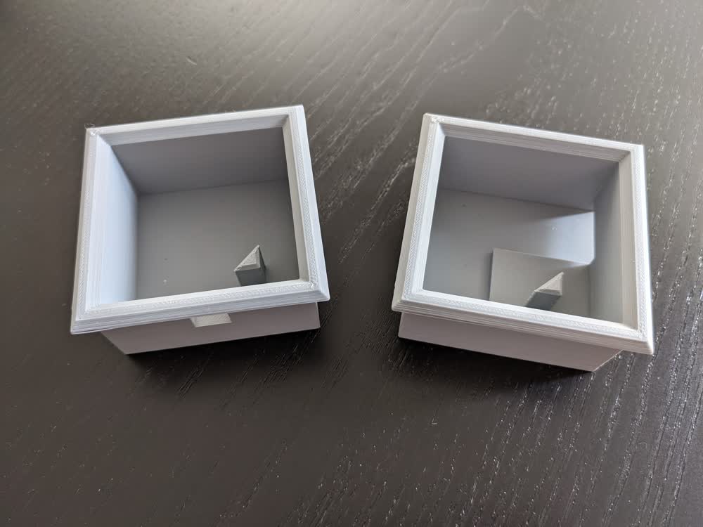
On my first iteration, everything seemed to go well, but I decided to change the location of the hole for the LED so it could go at the top of the block instead of underneath it. I also realized that the triangular aligning piece I had added was slightly off from where it needed to be, so the blocks wouldn't actually fit in. I had a slight miscalculation in my design, but I quickly fixed that. With everything good to go, I had two finalized pieces that would work well, but we were out of the same gray filament, so I printed off a new batch in a single color (white).
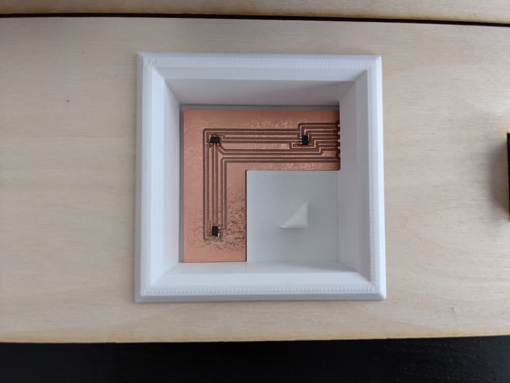
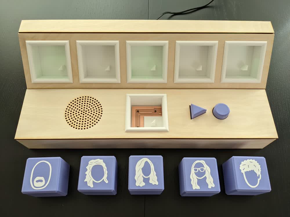
Here are some examples of the final holder pieces, along with the block reader PCB nestled into the reader piece (the elevated corner of that piece in particular is used to keep the block level).
Log #06: Vinyl Cut Face Decals
I wanted to decorate the blocks a little bit so my daughter could tell which block corresponded to which family member. We thought about putting their names on them, but decided to go with picture icons instead. Not because my daughter couldn't tell them apart, but we thought it would look better. My wife got to work and designed some amazing decals for me to cut out on the vinyl cutter.
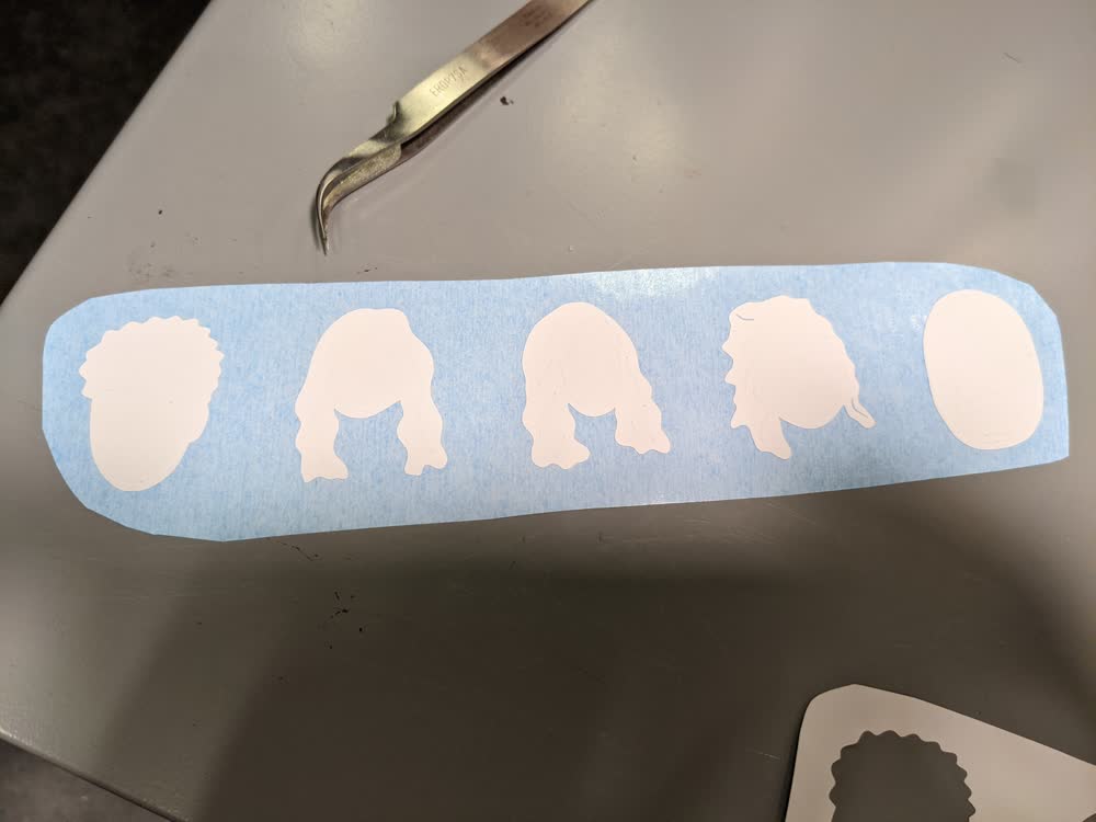
They cut out and transferred really well. I was stoked with how great they looked.
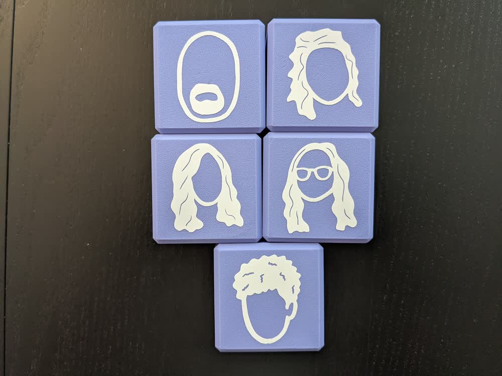
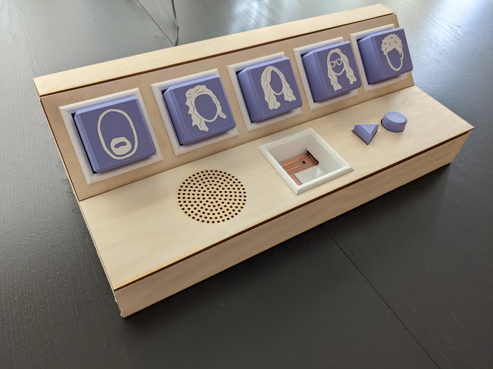
And they look even better once they're on the blocks!
I also made sure to get the magnets in there at this point. Turns out one of my magnets was slightly small and I thought I was going to need to glue it down well, but because it was the only one that was the wrong size, I got a replacement for it, and all of the holes were able to be filled with the same size of magnets. It was quite the tight fit. I had to use a hammer to get the magnets pressed into the hole slightly (not by hitting it with the hammer, but by pressing it all together, the hammer was magnetic and kept it in place well), then pressing the block upside down against the hard floor to get the magnet the rest of the way in. Those magnets aren't going anywhere... I also made sure to mark which side was going which direction on the magnets because the polarity matters in my code.
Log #07: PCB Design, Milling, and Soldering
Designing the various PCBs for this project was not as straightforward as I thought, but it worked out in the end. I decided to do a breakout design where everything would break out from the microcontroller (ATtiny3216 in this case), then connect together to other PCBs using headers and jumper wires.
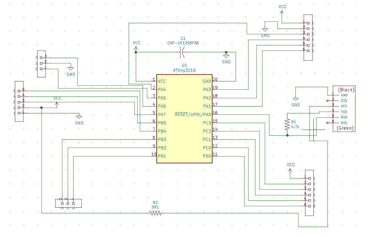
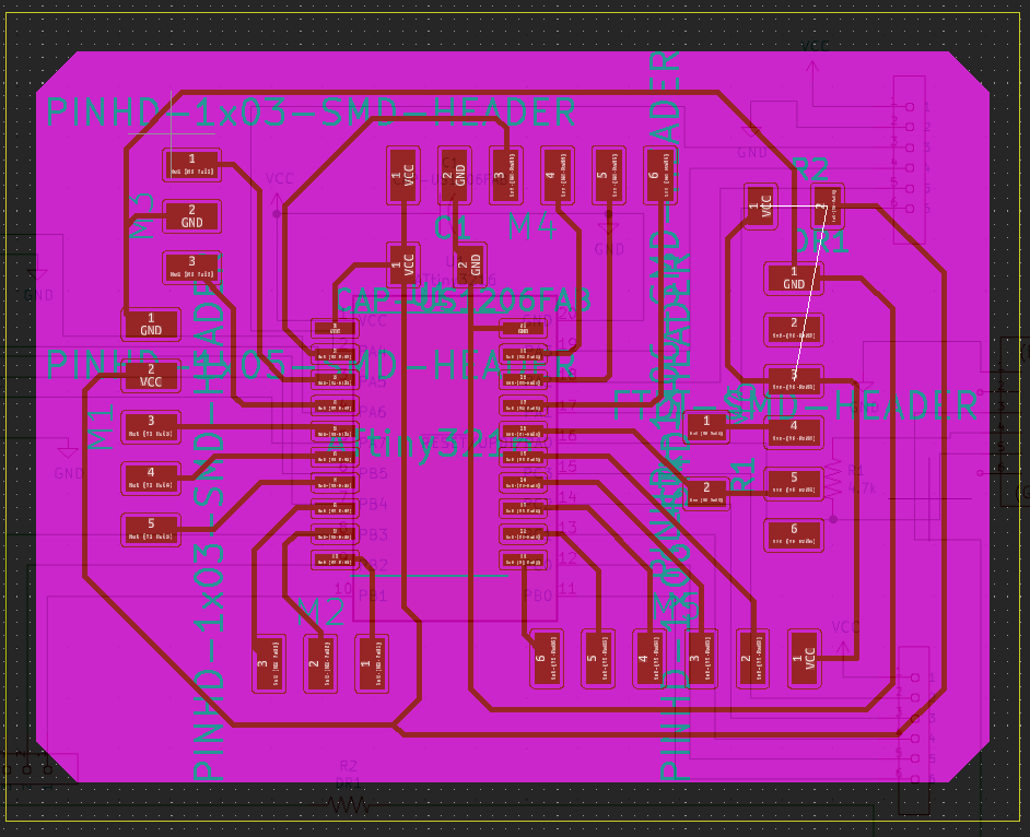
Here is the design for the ATtiny3216 board with all of its repsective pinouts going to headers.
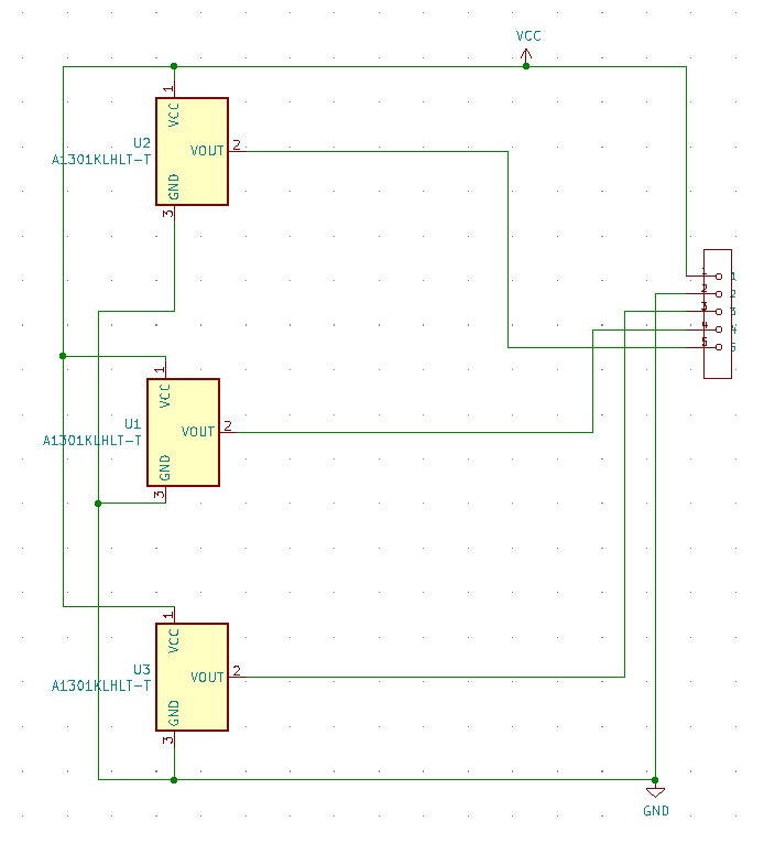
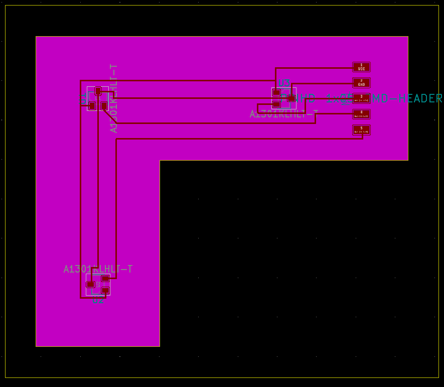
This is the Hall-effect sensor board that I had to design so that the sensors would align with the magnets in the holders.
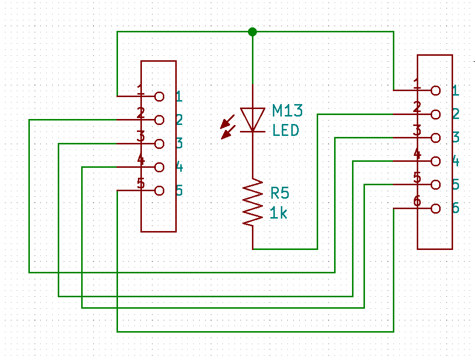
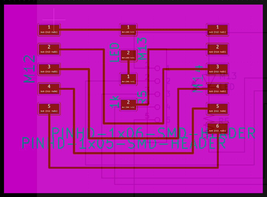
For the LEDs that would be shining through the holders, I needed a board that could separately carry the signals, rather than one really long PCB. I started designing different boards for each LED, then realized that I could get away with one design, but not hook up headers to every pin and just leave some pins alone. It worked out really well!
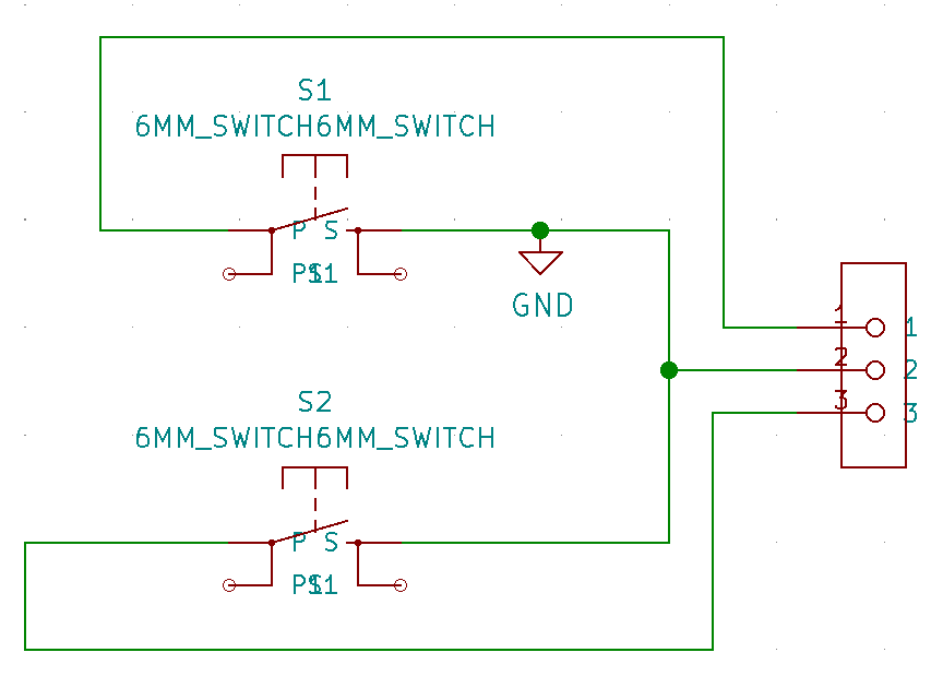
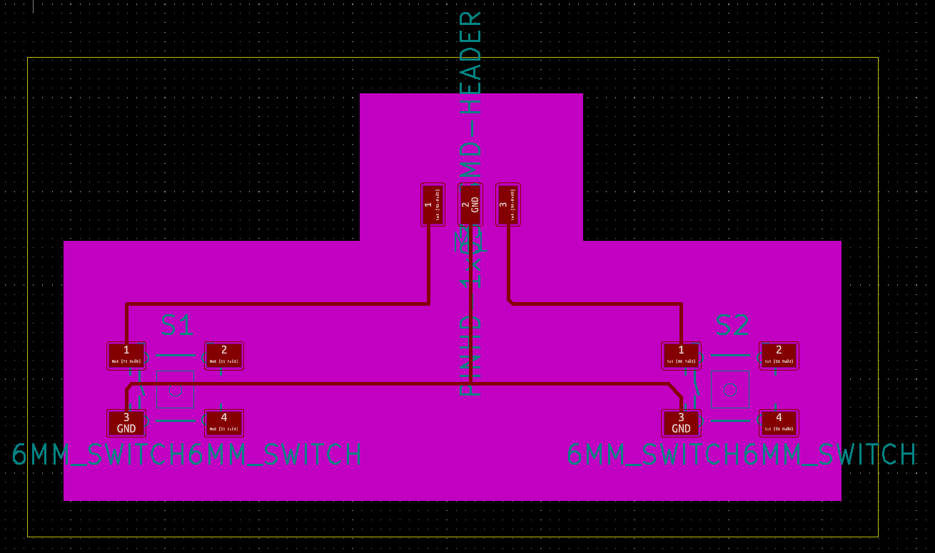
I also needed some button switches for the play and record button. That was pretty simple, but I still needed to make sure they aligned with the physical buttons, as well.
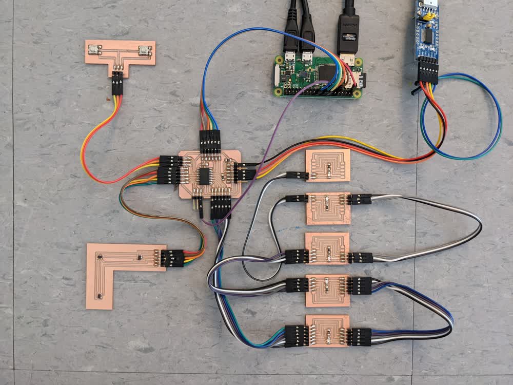
I had to fight my Clank machine a bit to get the settings dialed in again, and I used the straight edge rule to get a nice and smooth surface free of burring, then I was able to solder and get everything looking nice. Attaching some of the boards to the actual structure was a little more difficult because there was not a lot of room to work with, but everything got in there even though it's kind of a tight fit.
Log #08: Programming
This is where things started to crash and burn. From the explanation and demonstration video at the top, you can see that I got the sensors and outputs to work together well, but the deeper programming things like networking my ATtiny with a Raspberry Pi and then connecting the Pi to the internet just didn't go well for me. To be honest, it's mostly because I did not start that part early enough and ran out of time. However, the basics of how the device works are complete, and once I can get them to communicate well with the Pi, I can then connect to the internet, and I'll be even closer to my goal.
As you can tell, there is no mention of the speaker/microphone system for the actual recording and playback of messages. That will be addressed at a later time when I can get everything working with the Pi and connected to the internet. The Pi will then control the microphone and speaker, as well as handle uploading and downloading the recordings. Still more to be done, but this is what I've got so far.
Next Steps
- Reprint reader board holder so PCB is covered up
- Implement full communication between ATtiny and Raspberry Pi
- Find suitable web server for audio data
- Integrate speaker/microphone module
- Make and assemble second device to be shipped to Utah
- Get both devices communicating and testing well
- Configure SSH for Utah device's Pi for remote setup
- Ship to Utah for final testing