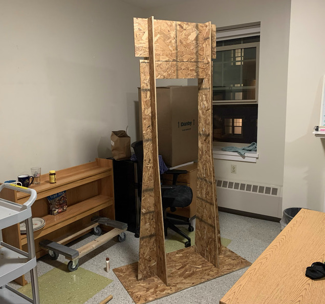
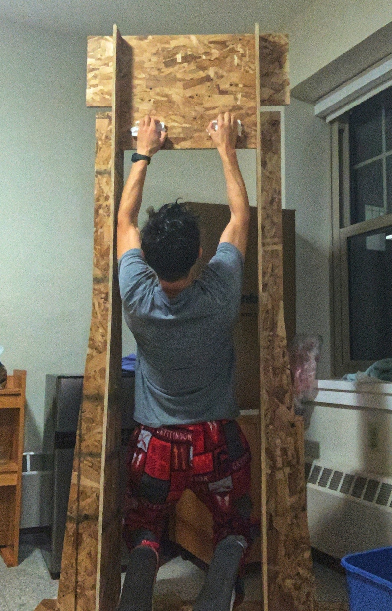
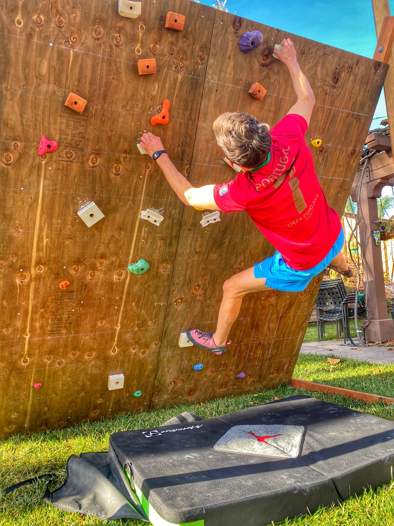
Here's the final project in action! Read below for more information!
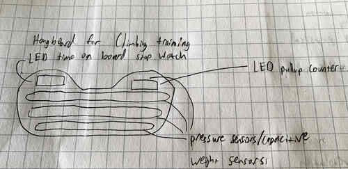
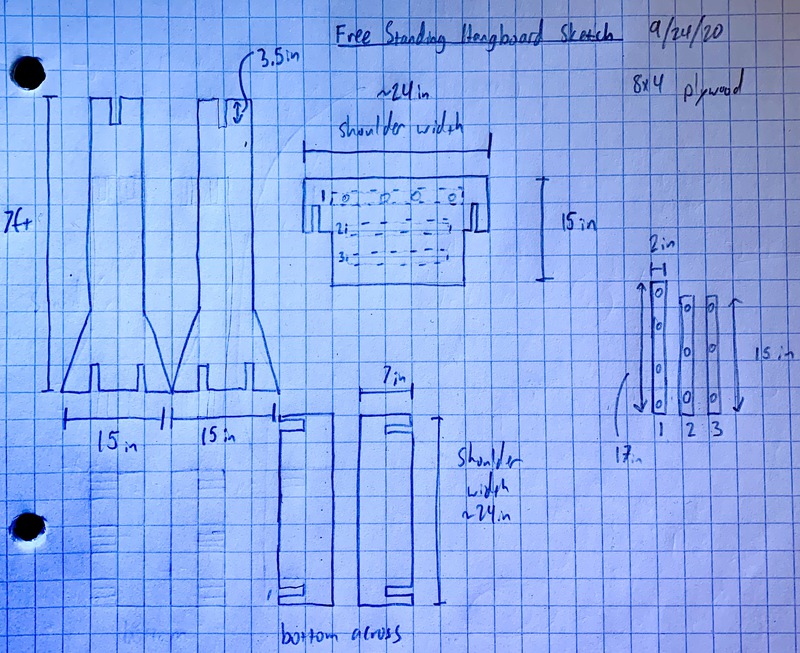
My first attempt at a sketch of a hangboard idea... Don't worry they'll get much better! Hangboards are used to increase finger strength in climbing. Normally you just hang off of them on increasingly smaller holds or with more weight (or with less/more fingers and different positions/holds). Training on them normally includes timing your hang and rests in between to do sets (like you might do for any other workout)
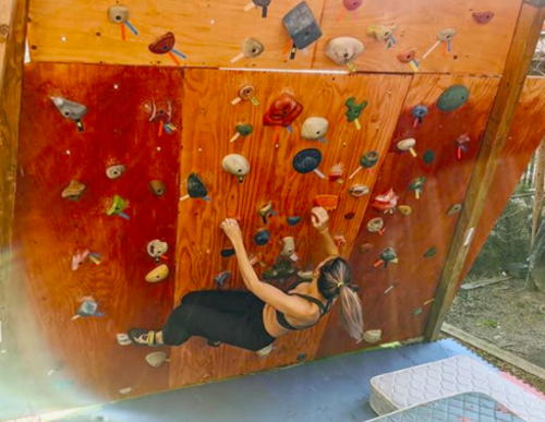
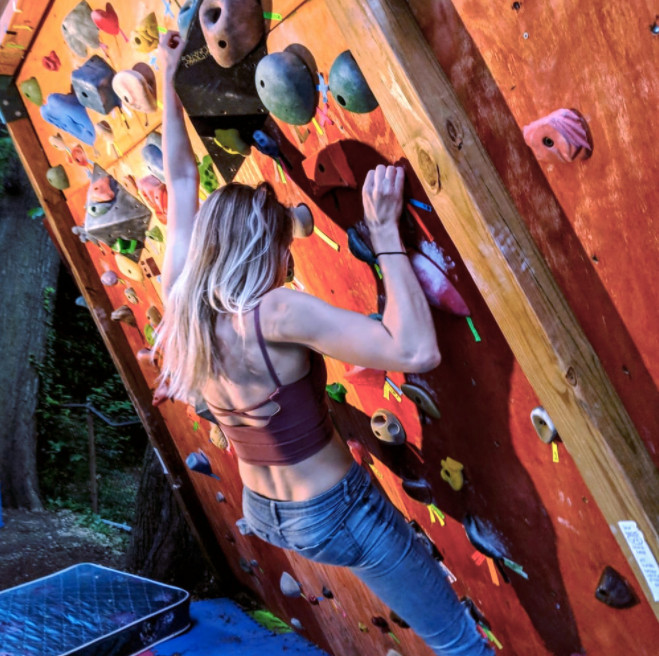
I also got to thinking I could make a full climbing wall in my room that would ideally be lightweight and portable and span about a 8ft x 8ft vertical space. The wall could also be overhung. The idea would be to make something like this, but a bit smaller and more portable(this is my friend Emma's wall!). Also with some electronic components
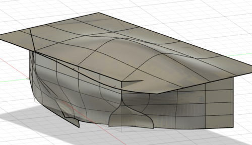
My first attempt at a free form climbing hold with a bit of an indentation at the top of it, but I'm not sure how to finish it and actually make it a volume. Also it's just weird, I will have to spend more time working on this later for sure.
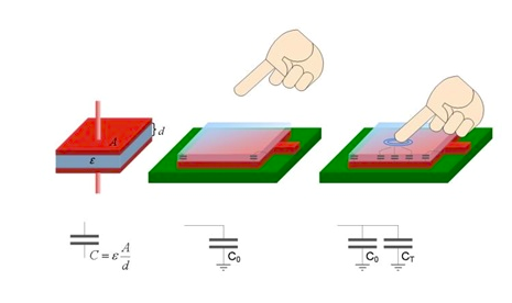
I am also thinking of finding ways to tell where a person has their hands and possibly feet. Capacitive sensing seems like the way to go. C = E0*Er*A/d E0 is the permitivity of free space, Er is relative permitivity or dielectric constant and A is the area of the plates (d is the distance between them). With a touch sensor there is only one plate and C0 is the environments capacitance. CT is the touch capacitor formed by the human's finger. The change in capacitance is measured to be able to detect a finger. And somehow I'll fit that into the hold, Maybe around the hold? (Information taken from electronicshub.org)
September 24th Update (WEEK 3)
I thought I'd start out by making a hangboard instead of a full wall.
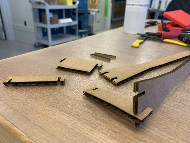
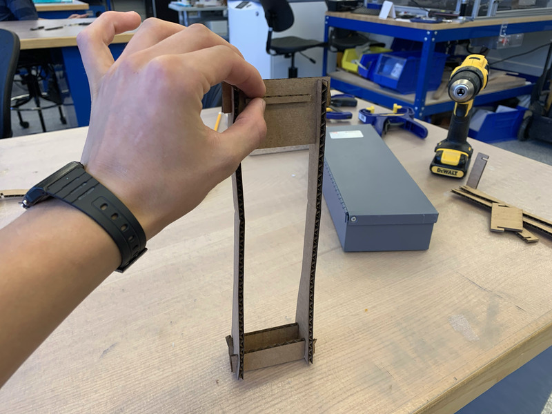
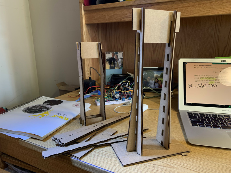
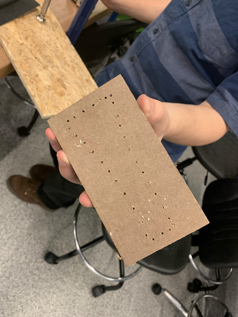
I got to work making a small model and lasercutting it. I forgot about thickness of the cardboard and it only fit together with much pushing and shoving (pictures 1 and 2). Then I got roasted by Anthony about my design. Anthony was actually super helpful though, thank you so much. So I added diagonal supports on the sides and made a baseplate instead of whatever I was doing before. It resulted in a much cleaner look. Also added a bunch of finger joints all over to reinforce my connections.
Now it was time to go to the machine shop. I had an online session with Anthony and made the emcam files. Then I went ahead and started using the mill.
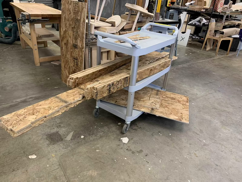
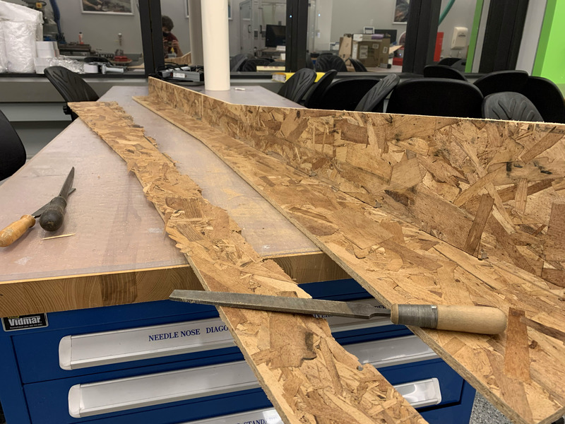
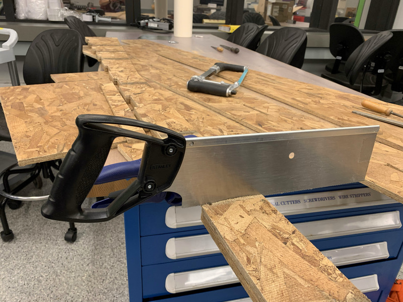
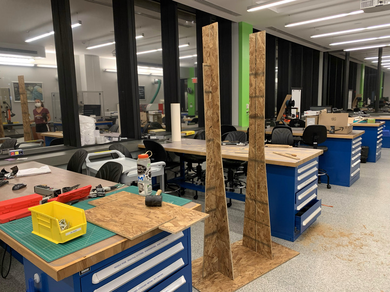
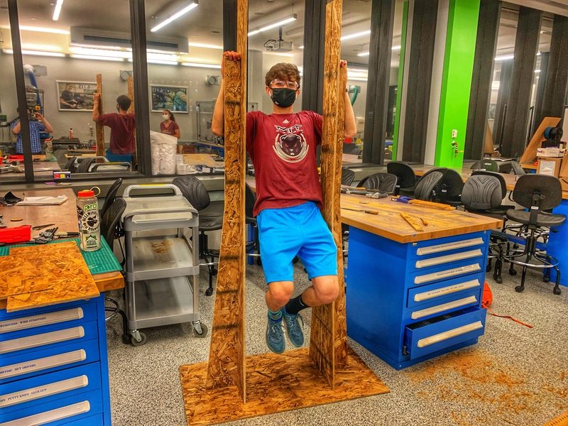
I got my wood pieces loaded up on the cart and took it to the EDS/Cypress shop. Funny story I was walking in the biking lane and right as someone went by one of my pieces fell off and nearly made him eat it. Thankfully that didn't happen. Thanks random biker for the words of advice: "Don't do that again!" I got everything up to lab and started filing the heck out of it. Also I had to saw off the ends of the side pieces, because they interfered with the piece that goes on top. Honestly it was way too hard to fit the joints together. I need to add way more spacing next time so that they fit together nicely. Buttttt anyways I was able to hang off of it so I'd call it a success.
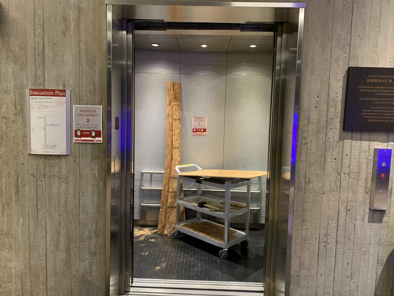
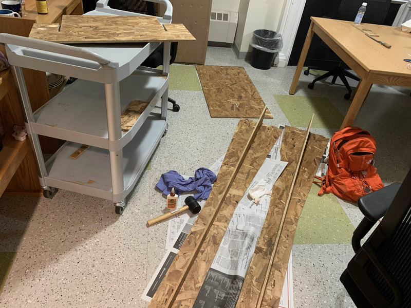
I loaded the wood pieces up in the elevator (had to take the big pieces off the cart because they don't fit in horizontally). Then I took them home to finish up the glueing. In the first stages of glueing the pieces together and realizing that with glue it's even harder to press the pieces together. Also it was 11pm and I was banging hard with the rubber mallet to make them fit. It was bad. Someone thought our floor was working out in the lounge. Thankfully no one came to tell me to shut up. Unfortunately I couldn't hammer the bottom of the stand into the baseplate well because there was nothing down there to hit as an edge. The holes for the jointes were just too tight. So unfortunately it stands, but isn't quite as sturdy as it could be.
October 1st Update (WEEK 4)
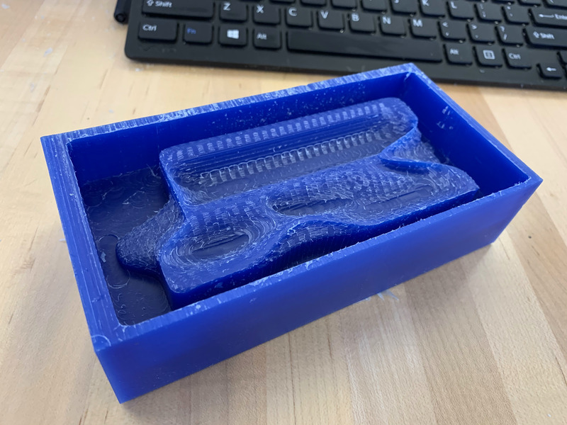
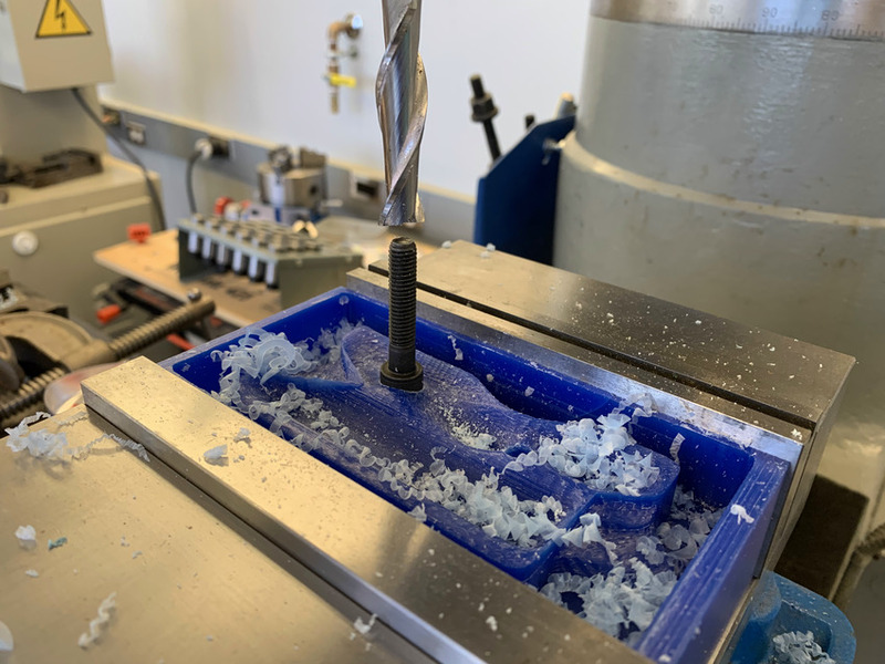
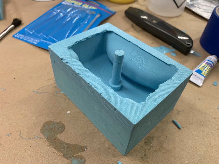
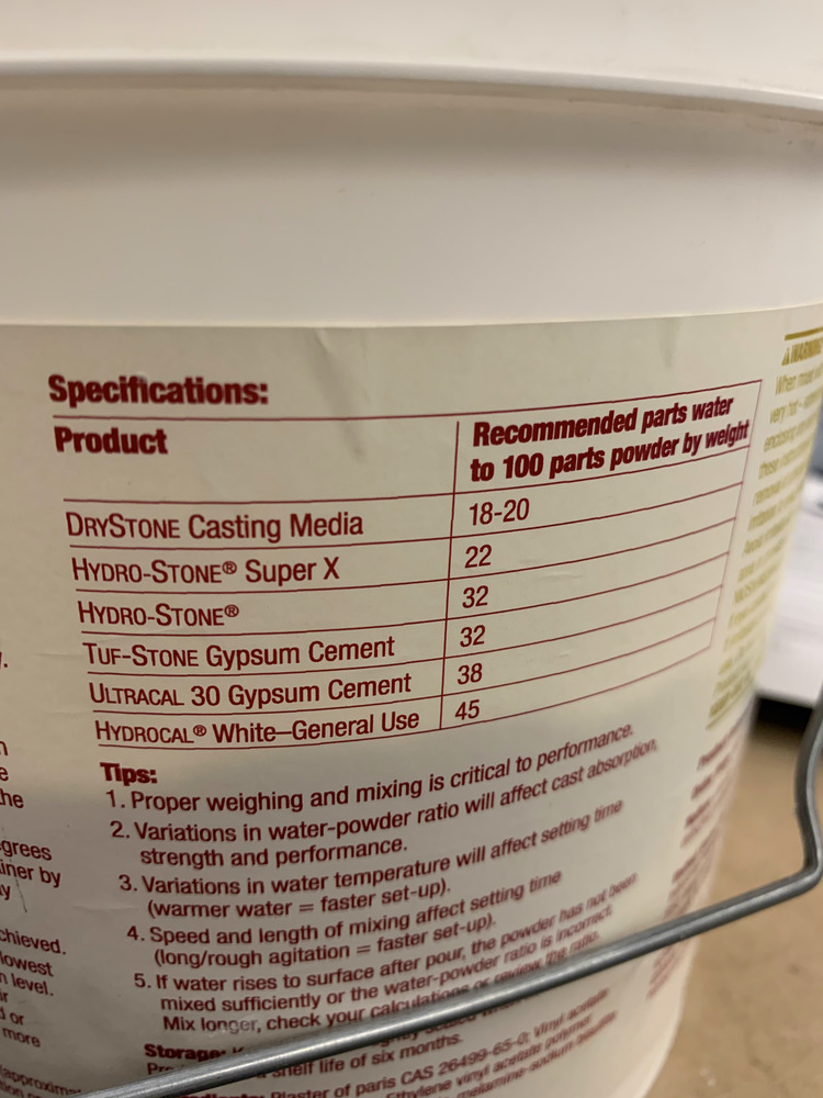
I thought it was time to start making some holds. I hopped on fusion and whipped up this bad boy. There were a couple things wrong with this including the fact I didn't leave enough spacing around my part so that a quarter inch drill bit could fit around everything. Thankfully Anthony helped me out to do it quickly and then cam it up on solidworks. I then milled it out and made a wax mold). I added in the oomoo and then used the cast to make it out of drystone. It came out very nicely, but now I have to add in the 3/8in diam hole to be able to bolt it to something. Also I need to build a wall to actually hang on!
Okay new idea. After talking it over with Anthony it would be sick to make each climbing hold its own interconnected module via bluetooth that communicate with some central processor.
The holds will have capacitive sensing and be able to communicate to the central processor when a climbing hold is in use.
Using bluetooth communication (could also be wifi) between each other they will be able to find the distance between each other and the central processor can solve this system and figure out a map of the climbing holds on a plane. BLE distance sensing
With a map of the holds paths between them could be generated at random and possibly difficulties could also be estimated.
Also using the capacitive sensing a person's workout/movement on the wall can be tracked and analyzed for difficulty.
October 27th Update (WEEK 7)
I made a small flow diagram for one of the electronic systems on one hold.
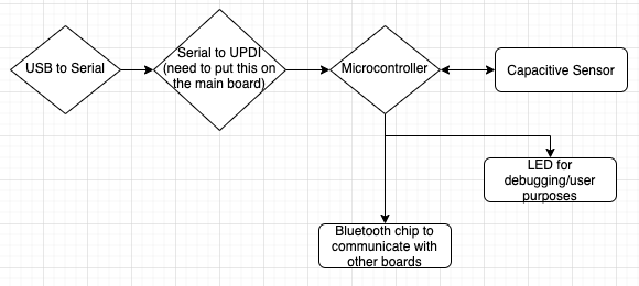
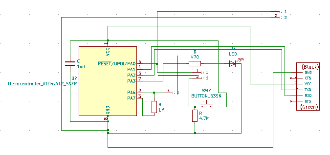
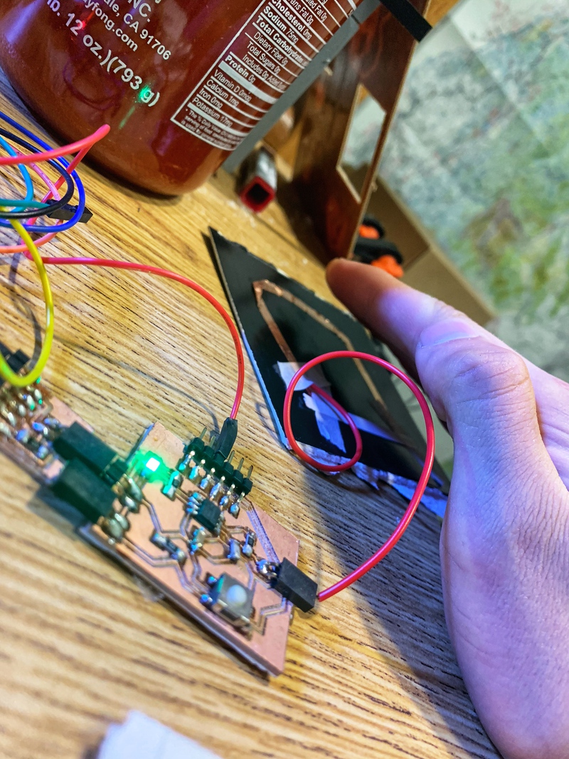
I went ahead and designed and built a circuit with the capacity to do everything above, but the bluetooth sensing. I was able to get the LED to turn on when a hand comes within a couple inches. I would like it to be abit more sensitive I think, but for a first attempt this went very well. Neil also mentioned a different more robust capacitor sensor that controls both ground and the signal using a square wave.
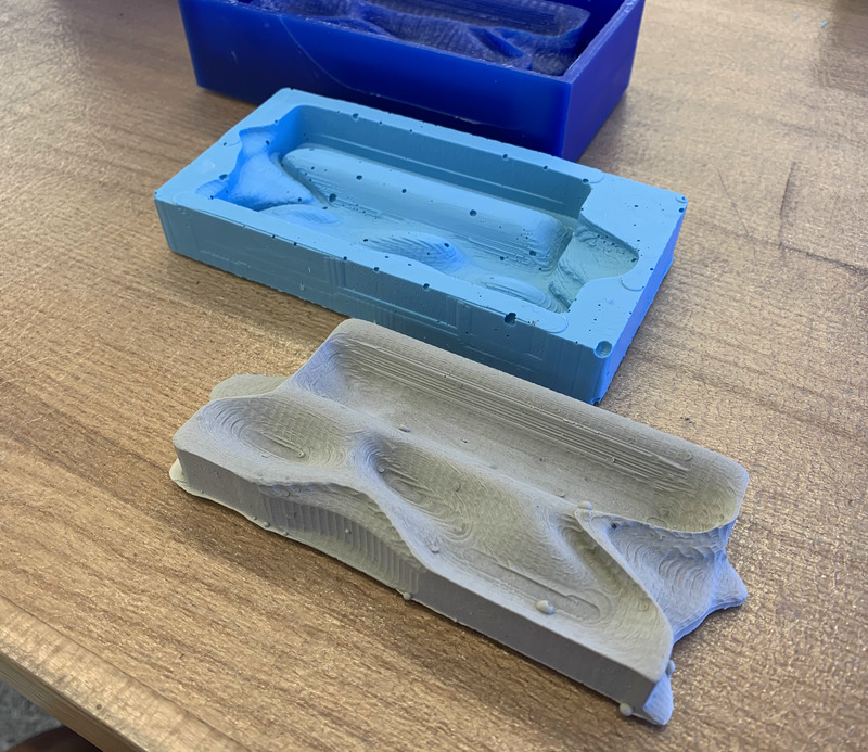
Simultaneously this week I also went into lab and worked on my climbing holds to be able to mount them to my at home free standing hangboard. My second attempt at an oomoo mold went much smoother and there were significantly less bubbles. Finally I made 2 drystone casts and mounted them. I was able to hang on them!
Sweet so now I have a circuit that can detect a hand and handholds I can mount on my free standing structure. I also did some quick sketching and I figured out that just knowing the distances between all the holds will not constrain the system unless I use another reference point or some other system.
I think for now the game plan will be for the holds to be able to communicate to one central microcontroller about which holds are being currently used. Initially all the holds wouldn't need their own microcontroller. Everything could be connected by wires initially. Next steps could be: making each hold have its own circuitry connected through bluetooth to other devices and/or connecting the main microcontroller to the internet to toggle things on a website.
November 11th Update (WEEK 9)
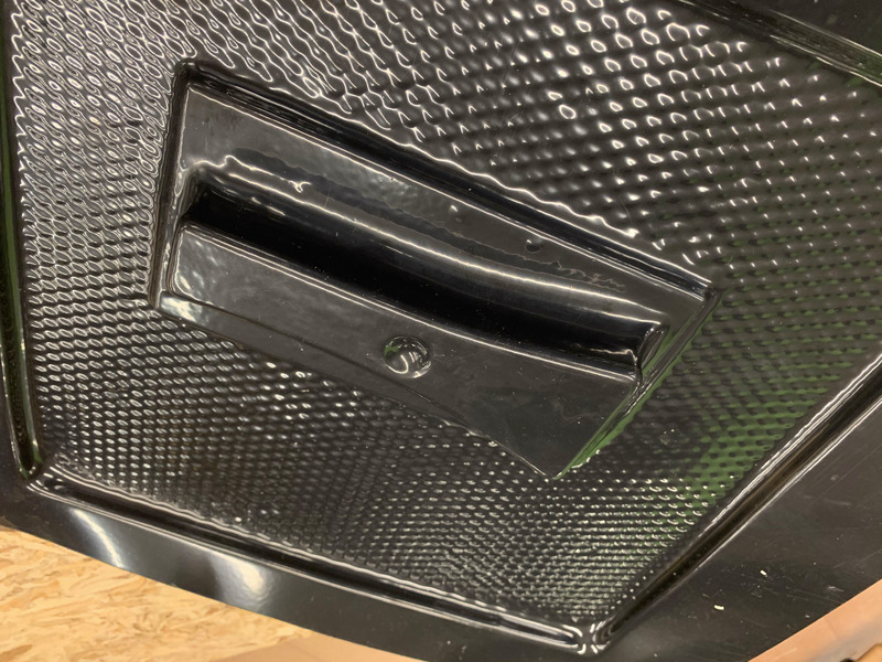
This next bit is a lot on different kinds of holds. I tried to make a pinch hold using the thermoform to get the cool plastic texture that comes with the finished product.
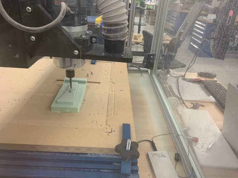
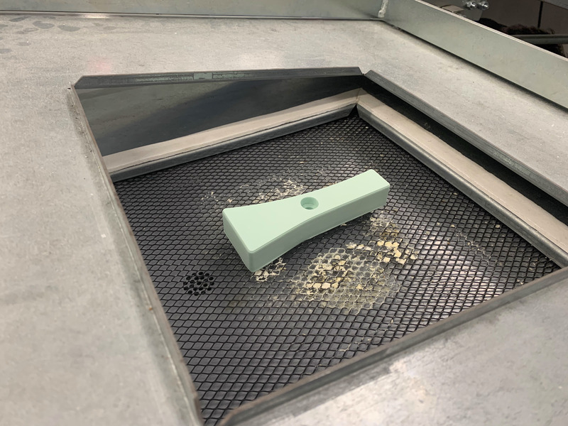
First I designed the hold with a recess for a bolt and milled it out as you can see below.
Next I used the thermoform machine to pull the plastic over the hold, but as you can see in the right picture I didn't make any holes in the middle of hold where the hole for the bolt should go so the plastic didn't vaccuum down there obviously.
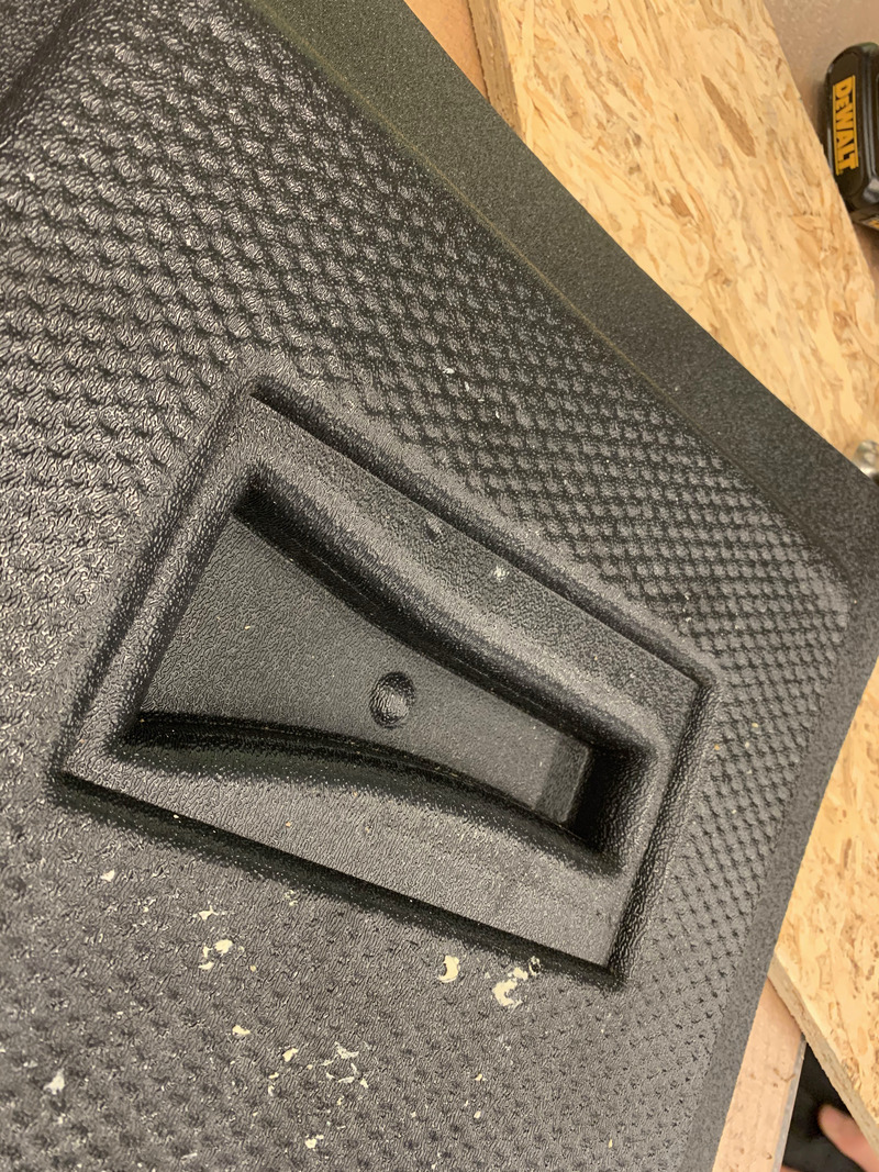
I tried again with the appropiate holes, but the vaccuum created was not strong enough to pull the plastic all the way down the hole.
Next week's update shows how I just drilled out the hole and made a 3D plastic piece to go inside instead.
November 18th Update (WEEK 10)
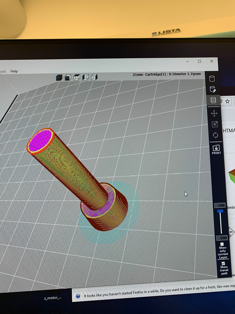
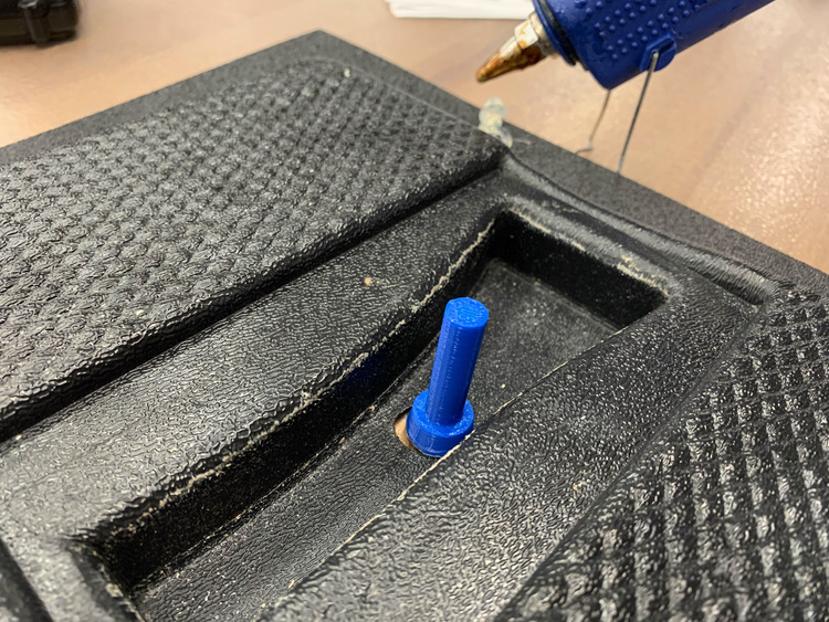
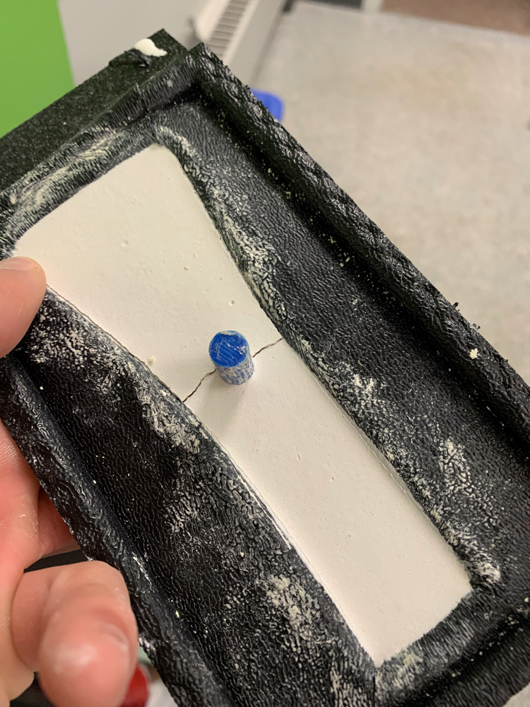
I made this small pseudo bolt to put in the black thermoform mold above.
I printed the piece, deburred the hole to fit it properly and then hot glued it in. Ready to make a hold with it now!!!
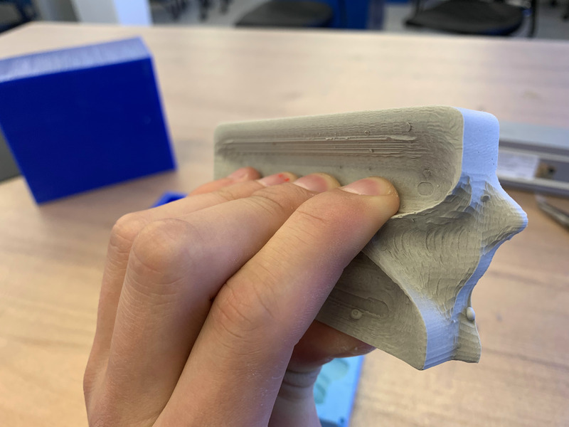
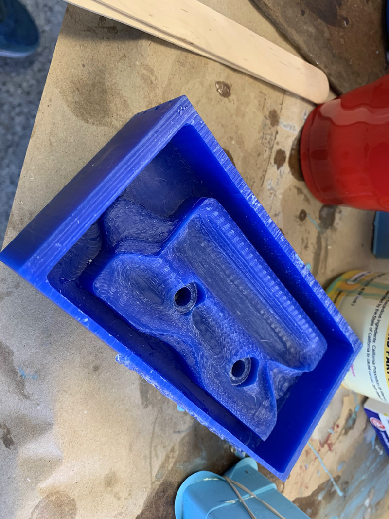
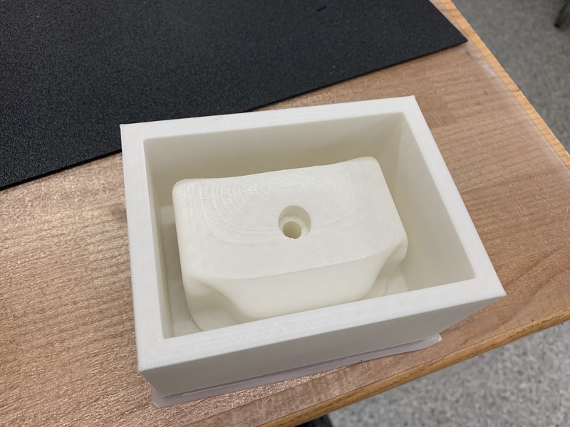
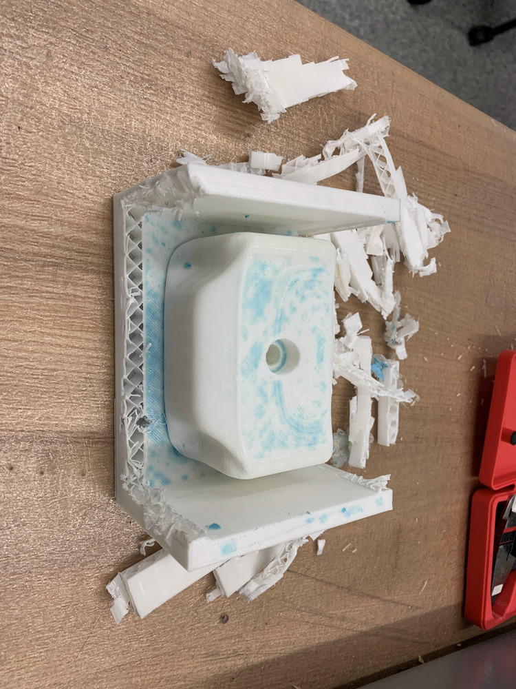
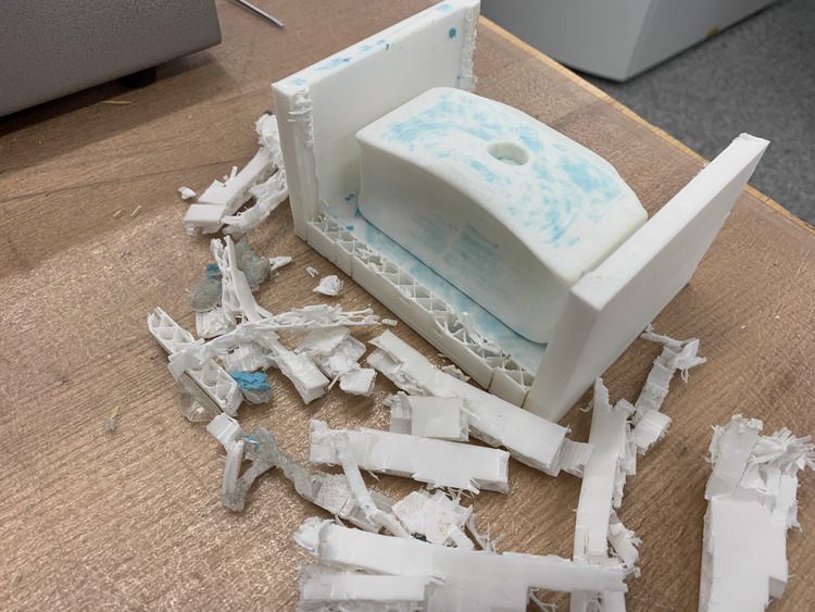
Then I went ahead and made a climbing hold that was more jug-like and would be more comfortable with a nice lip and indentation at the top. I did this using a form in Fusion.
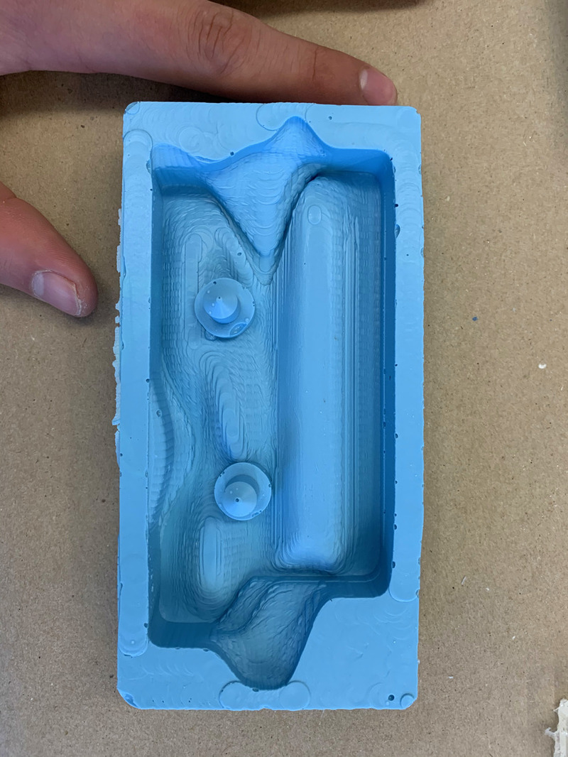
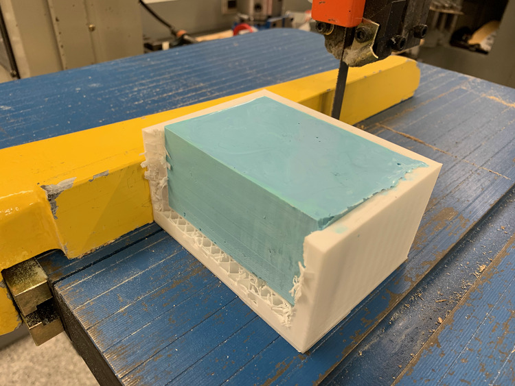
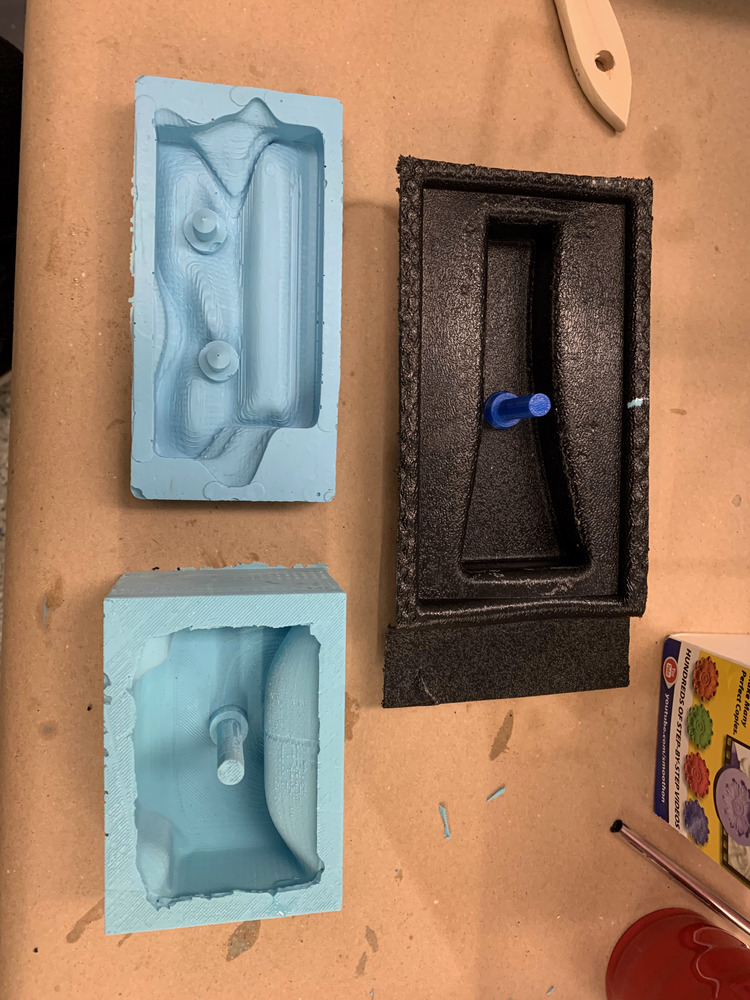
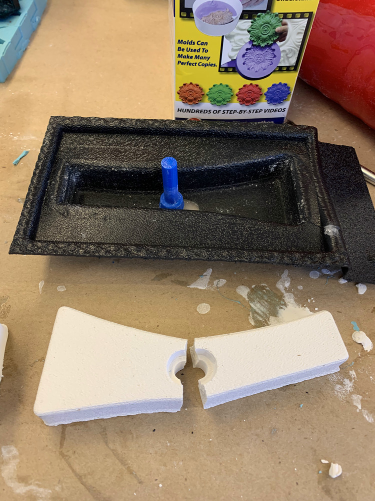
I poured the oomoo in, but it was a mess to take out and was a combination of using the bandsaw and wire cutters, but I got the oomoo mold out!
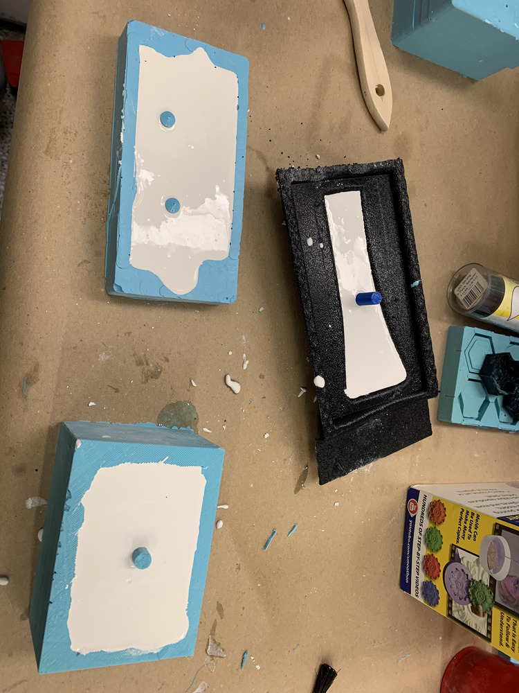
Next it was time to to pour in the concrete and make as many holds as possible before going home!!!
They came out well except for the pinch hold:( I tried again and was able to get 1 of them though!
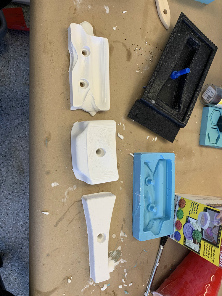
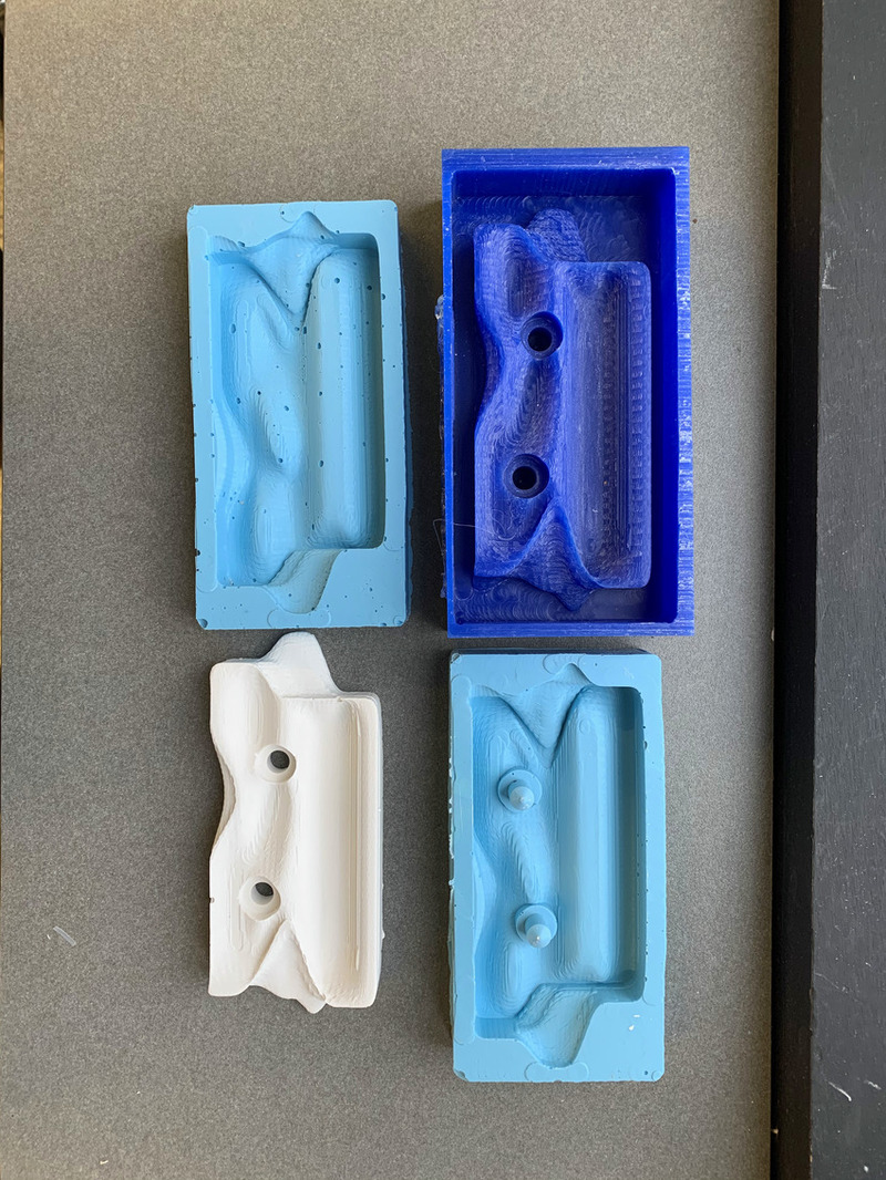
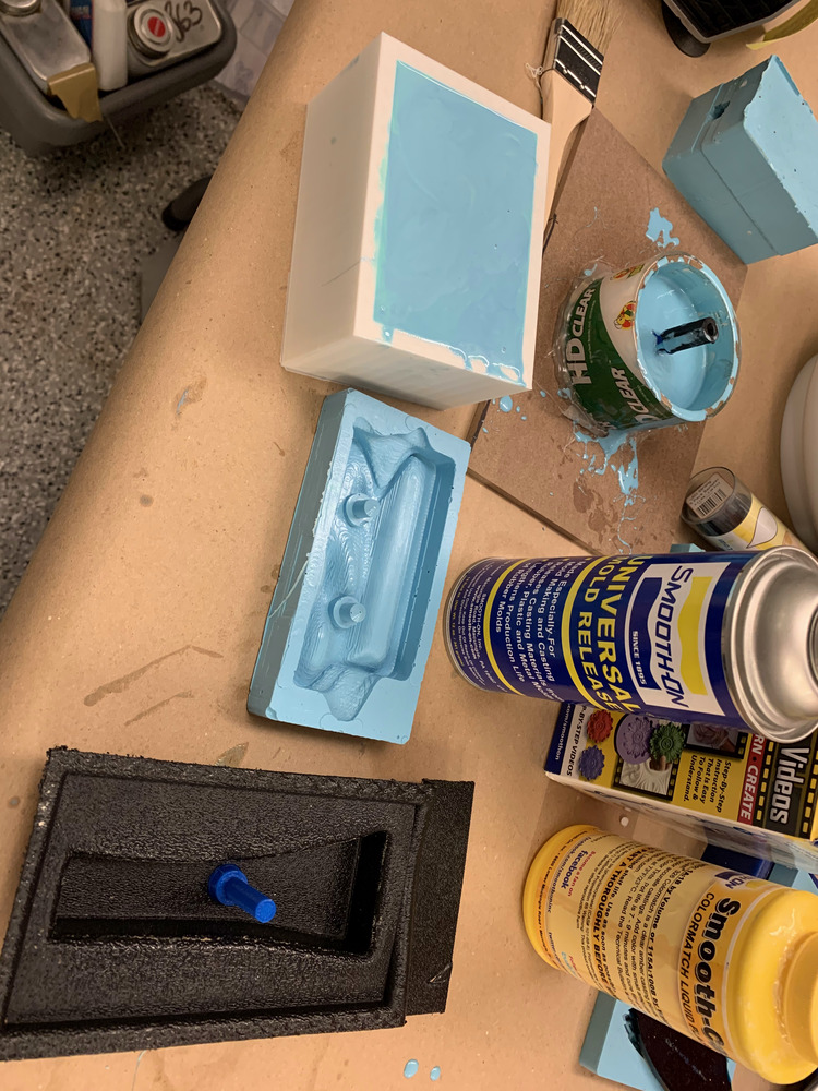
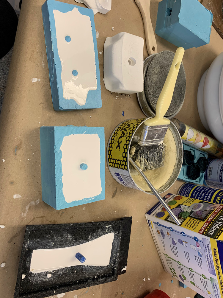
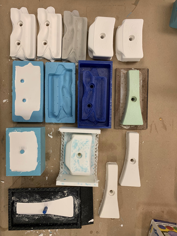
Here is a picture of almost all of my mold-making antics for the semester. I definitely have a much better grasp of mold-making now, having tried 3 different processes to make my molds: milled wax to oomoo to concrete, milled material to thermoform to concrete, and 3D print to oomoo to concrete.
November 25th CLIMBING WALL
Well now it's time to work on the actual climbing wall! I am using inspiration from my friend Emma Kowal's page, page on REI's website by Graham Averill, and a page on instructables by mga12.
I decided to mostly go with mga12's wall because I didn't want to make a huge structure and I also didn't want to use a jungle gym pre-existing bracket. In order to make it a little more adjustable instead of having a fixed angle, I decided to use bolts for the overhung wall so that I can later easily drill new holes for the bolts to change the angle.
Climbing Wall Shopping List
- 4 12ft 2x4in studs ($53.92 - top choice redwood)
- 6 8ft 2x4in studs ($74.28 - top choice redwood)
- 2 4x8ft 3/4in thick plywood sheets ($119.96 because I got treated plywood)
- 4 4in long 5/8in diameter bolts ($7.52)
- 4 5/8in washers ($1.88)
- 4 5/8in lock washers ($1.36)
- 4 5/8in nuts ($2.24)
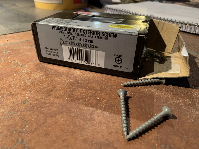
- a bunch of 1.25in deck screws ($10? IDK I had these at home)
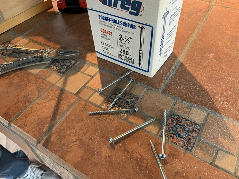
- at least 20 of 2.5in pocket-hole screws ($10? IDK I had these at home)
- 100 3/8in t-nuts ($16 on Amazon)
- 20 3/8in diam 2in long socket head bolts ($30 on Amazon)
- 4 90 degree metal angle brackets ($16? IDK I had these at home)
- also because my holds had nonstandard bolt diameter I also bought (But I won't this include this in the total because ideally all your holds are for 3/8in bolts!):
- 5/16 socket heaad bolts various lengths
- 10 5/16in nuts
- 10 5/16in washers
- 10 5/16in lock washers
TOTAL COST: 53.92 + 74.28 + 119 + 7.52 + 1.88 + 1.36 + 2.24 + 10 + 16 + 30 + 16 = $332.2
This was more than expected, but if you don't get the treated wood or the top choice studs then I thin this can be reduced to at least $250.
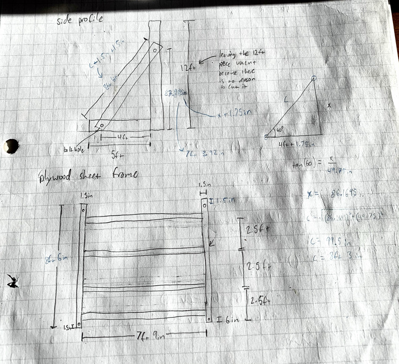
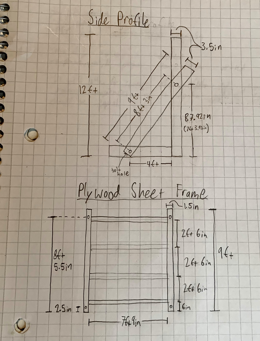
Here are my initial sketches for the design. With this new bolt design I will be able to construct the overhung wall/frame and the two 90 degree side frames separately and then join them together. UPDATE: I redid the sketch after for clarity and posterity sake. Especially since I edited the initial plan(tldr: look at the second sketch- also tldr means "too long didn't read").
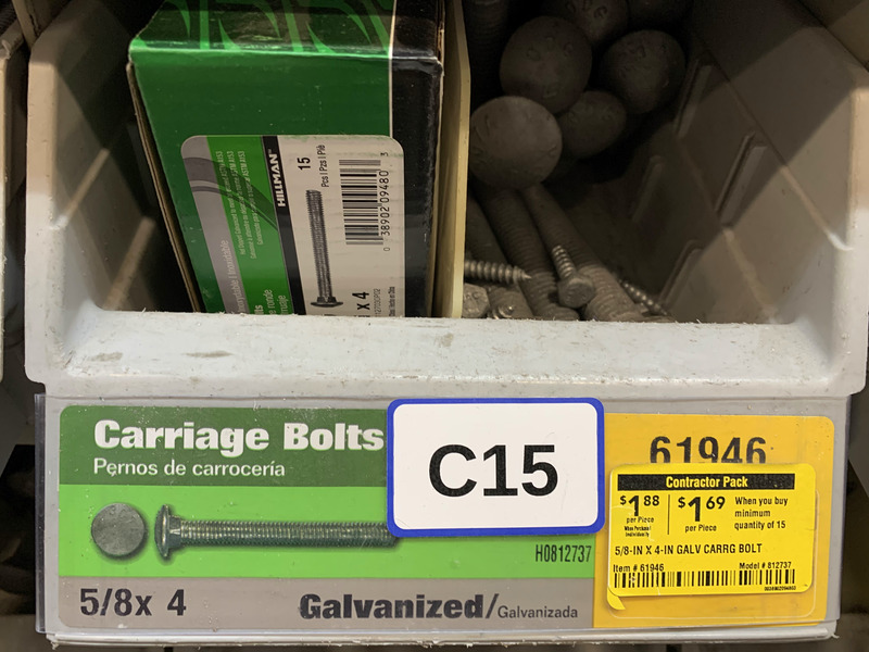
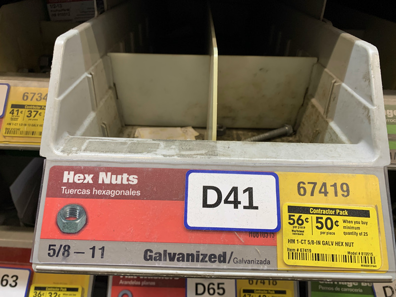
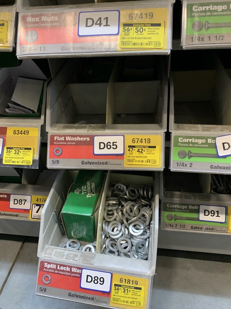
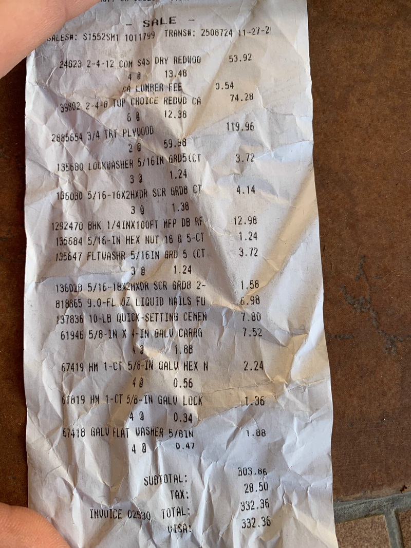
Here is some of the hardware I bought (the carriage bolts for the structure). The receipt shows some other purchases. Because I bought high quality redwood and treated plywood this came out to be fairly expensive.
I also bought some additional bolt hardware for my specific holds because I accidentally made them to be sized for 5/16in bolts instead of 3/8in which is the industry standard. Later on I bought the 3/8in t-nuts and socket bolts on amazon to use for the majority of my holds.
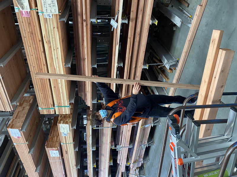
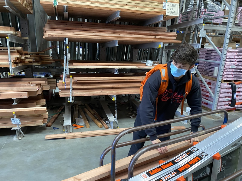
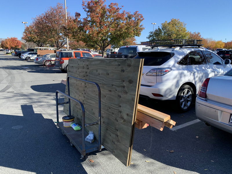
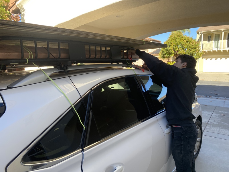
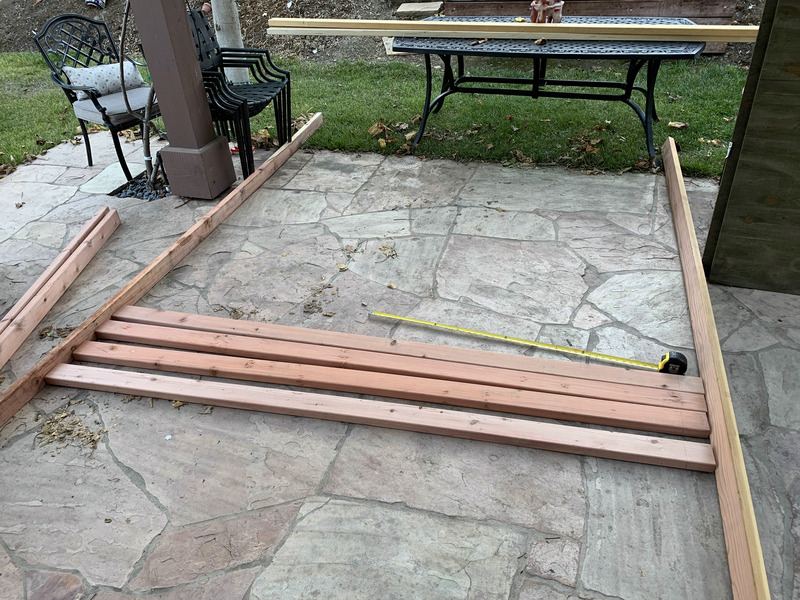
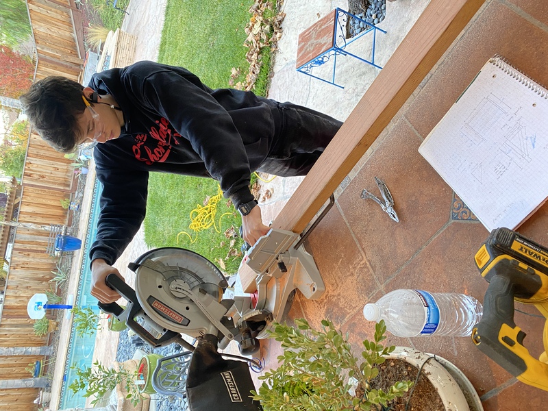
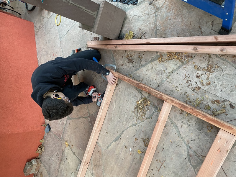
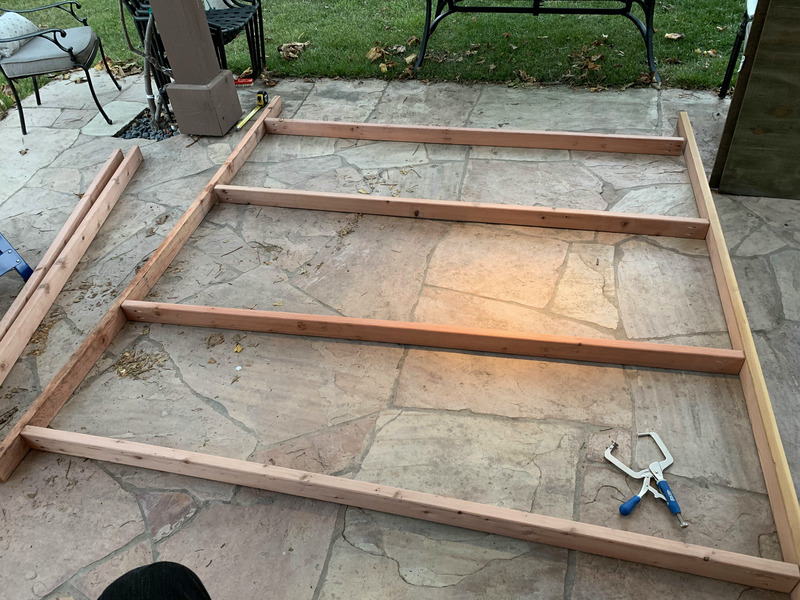
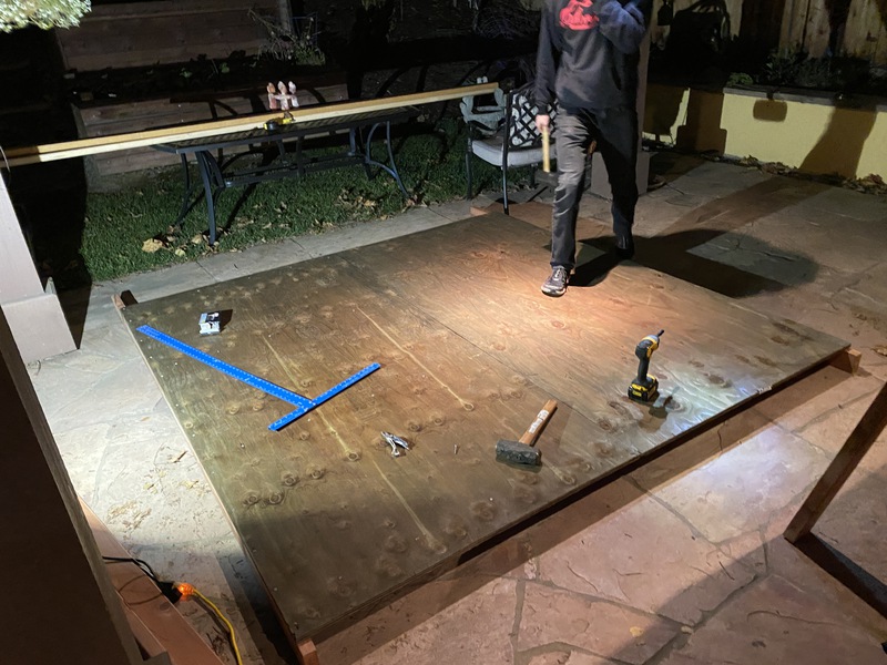
After some ingenious strapping on the car and some moving to the backyard it was time to start mapping it out. I proceeded to cut the studs going across the back of the wall to 7ft 9in (becomes an 8ft length when attached to the two side studs each with 1.5in thickness)
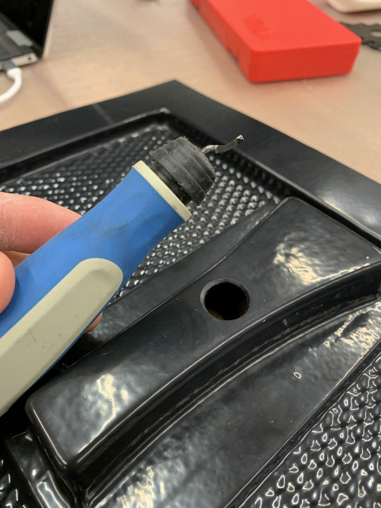
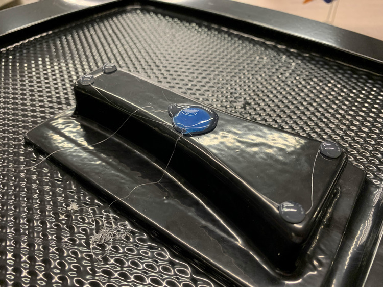
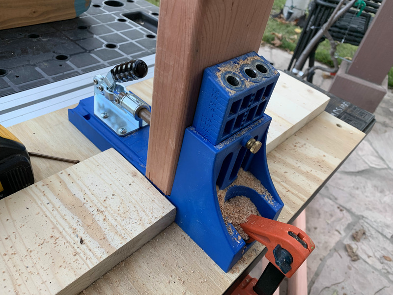
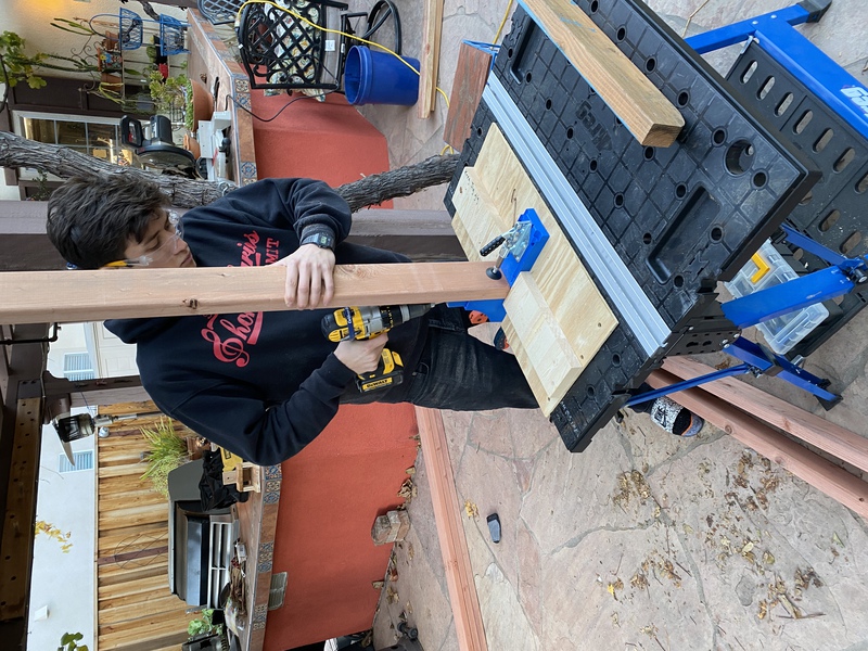
The little blue device was used to create diagonal socket holes for screws to join the studs together at a 90 degree angle.
I used 2.5in pocket-hole screws for these. Make sure everything is flush!
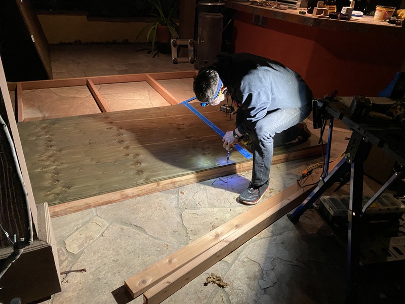
Once the wall frame was done I went ahead and placed the plywood sheets on top one at a time making sure to note where the studs were by making marks on the outside studs and using a straight ruler to estimate where they would be.
Then it was just a matter of putting screws all over. I aimed for about 10-12in between each screw, but you could stand to put a few more.
Next step was making the 90 degree support on either side. I again used the pocket hole technique to join them and used some metal angle brackets on the sides to reinforce the corner. I drilled the two holes as well on each side to be able to attach the wall.
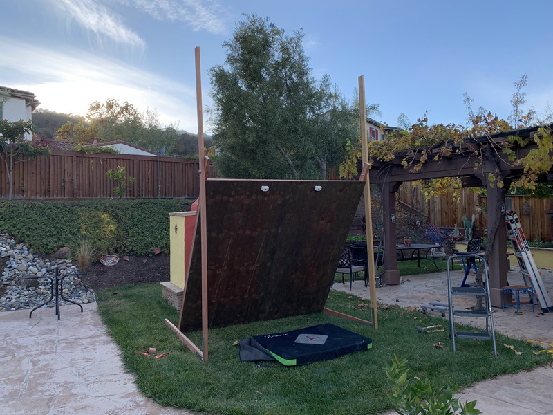
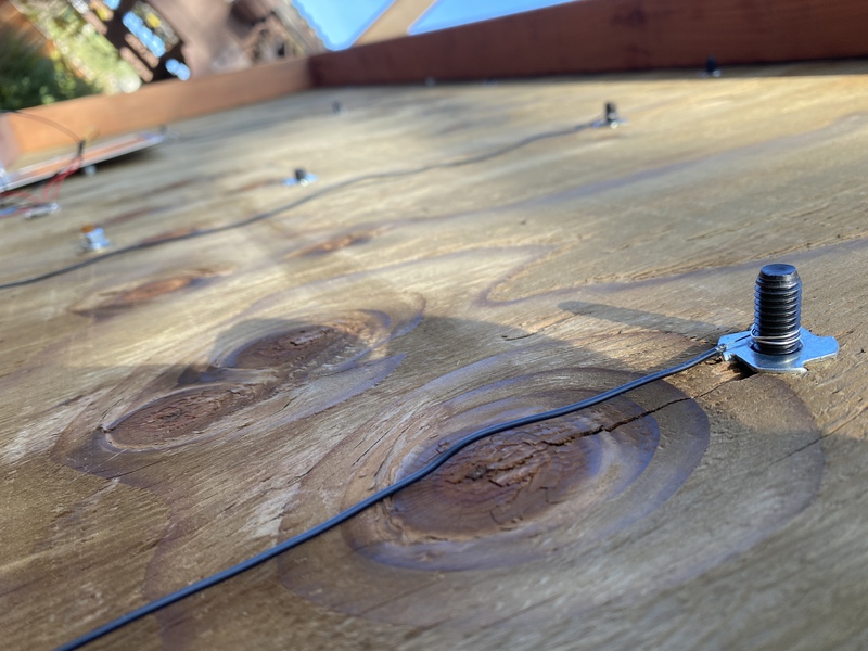
Then it was just a matter of dragging everything into place and placing and securing the carriage bolts with a washer, locker washer, nut combination.
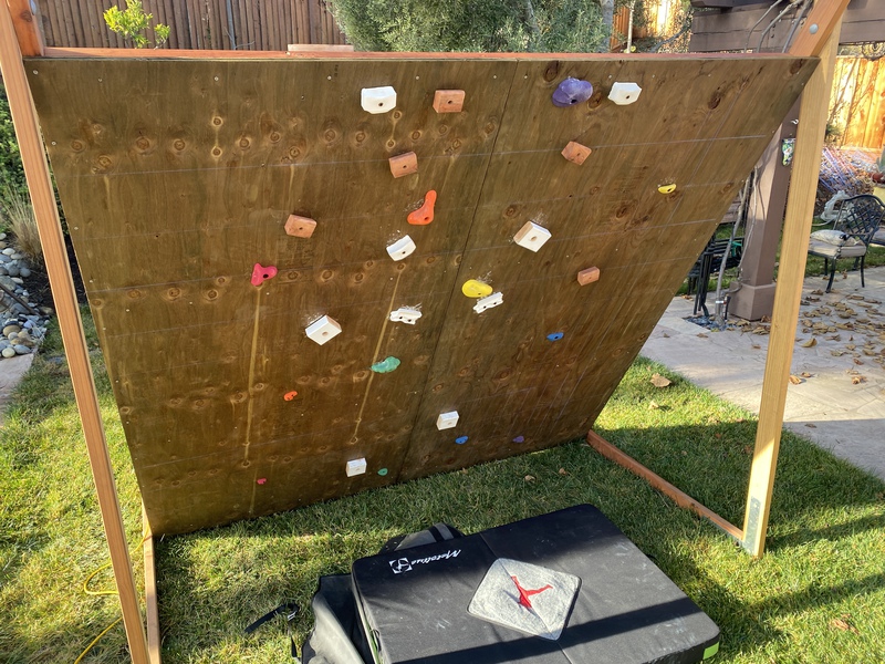
The Wall is UP!
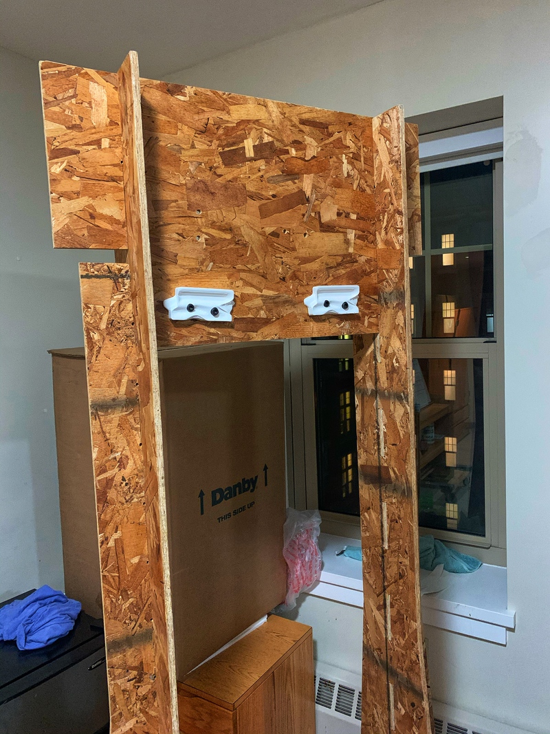
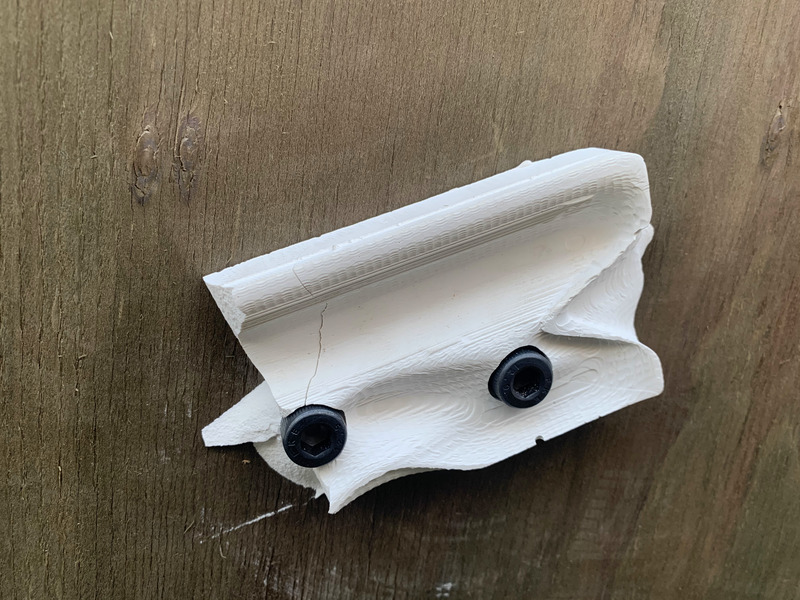
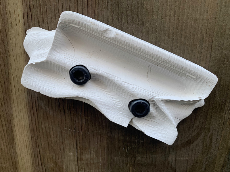
I started screwing on some of the holds and unfortunately the two skinnier holds cracked uner the tension. The thicker jug-like holds at the top are strong and could support my weight. You can see the cracked holds below :(
I was able to make my FIRST BOULDER PROBLEM!!!
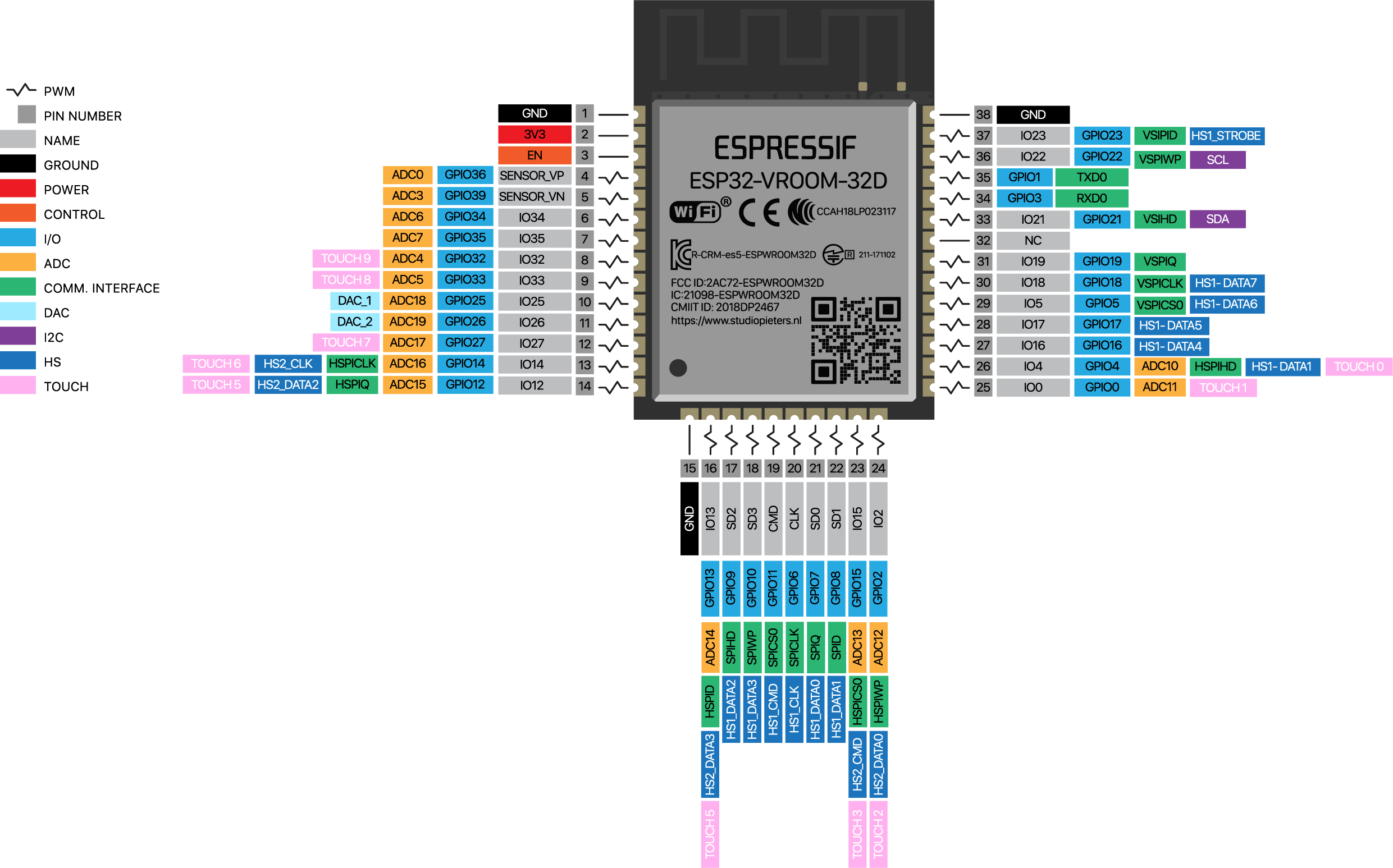
Now it's time to integrate the ESP32! The esp32 has a built-in library for capactive sensing so I'm going to use that to sense when people are on a hold. I am using this page to make sure I have the right esp32 pinout
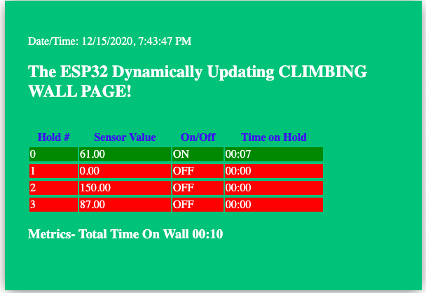
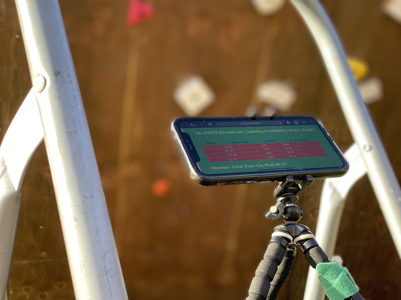
Anyways I coded up a website that is dynamically updated via a .ino file that is loaded onto the esp32.
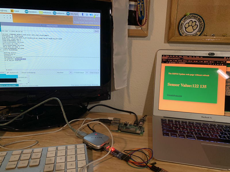
I came up with this web interface to show the sensor values, whether the hold is in use and the time the hold has been in use. The total time at the bottom is the total time someone has been on the wall.
You can learn more about how I used AJAX (Asynchronous JavaScript And XML) to dynamically update my webpage in Week 11. My code for the final project is here: my index.h file and my .ino file
My code is commented, but the short version is the ESP32 serves up a pre-specified website that is contained in the adjoining index.h file and that contains sections and style attributes I plan to update dynamically. This html also contains javascript to ask for these values every second.
The .ino file is where the ESP32 measures the capacitances and tracks whether a hold is being used and for how long, this data then gets sent to the website. There is also a calibration period at the start of the code to set default sensor values that are used to threshold new values to figure out if a hand is on a hold
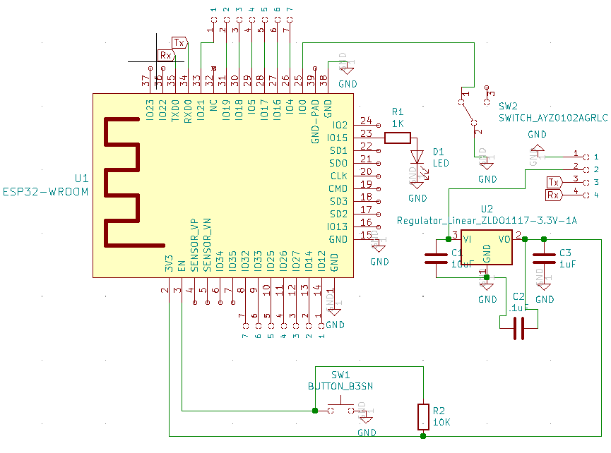
Time to make my final pcb. I basically just made a breakout board. I designed it as you can see below to be a little simpler than the original board I used. It has a led for debugging and 14 pinouts (7 on each side) for capacitive sensing and anything else that might strike my fancy. As you can see my schematic drawing has gotten better. I used this link to do the routing for Kicad
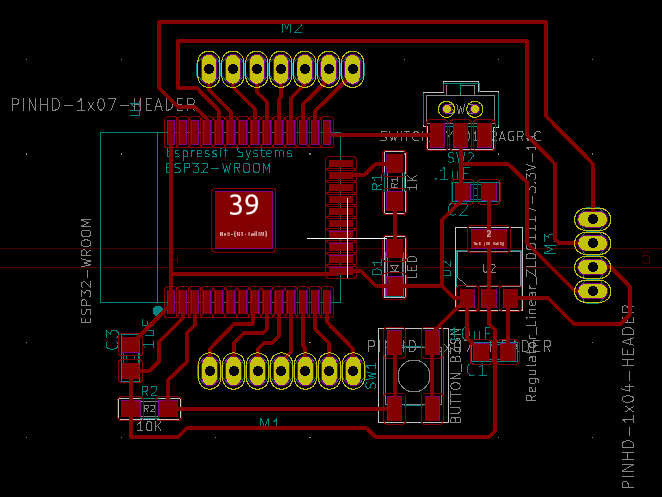
I had a semi meltdown trying to route because pcbnew in kicad wouldn't display anything other than a blank screen, but after a little over na hour it turned out I just needed to revert the graphics to a more stable version by pressing F11. Anywayssss. Now I'm having problems with clank, but hopefully it gets up and running. UPDATE: I did not get Clank (my pcb mill running so we're just going to have to go with the board I already milled for use in week 10 and 11)
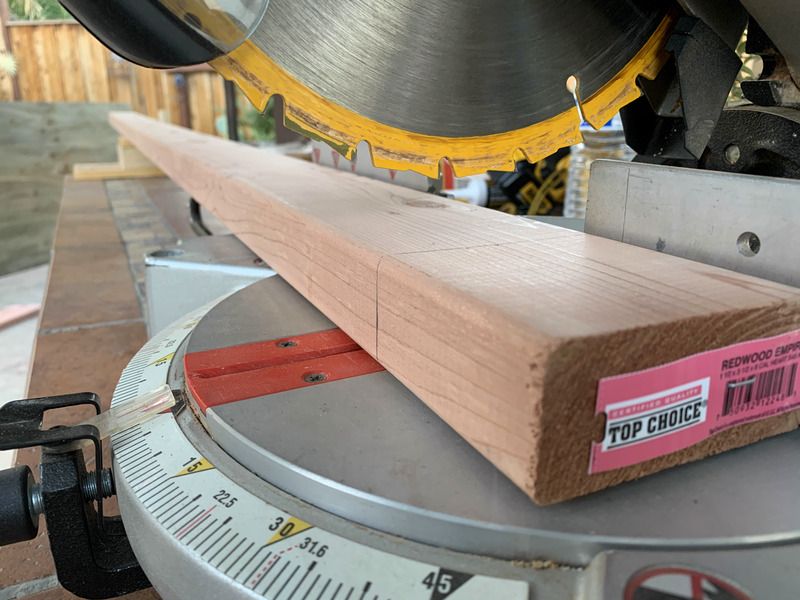
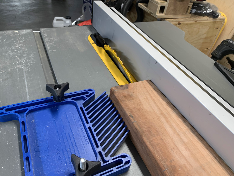
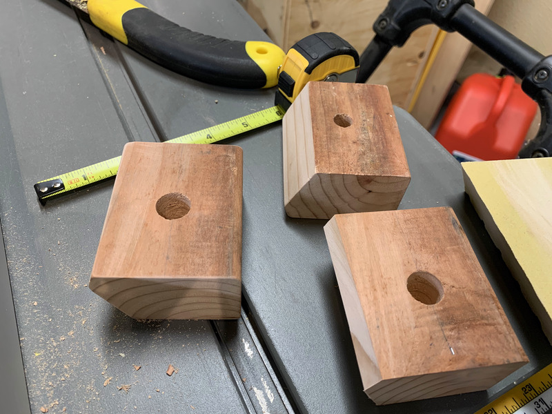
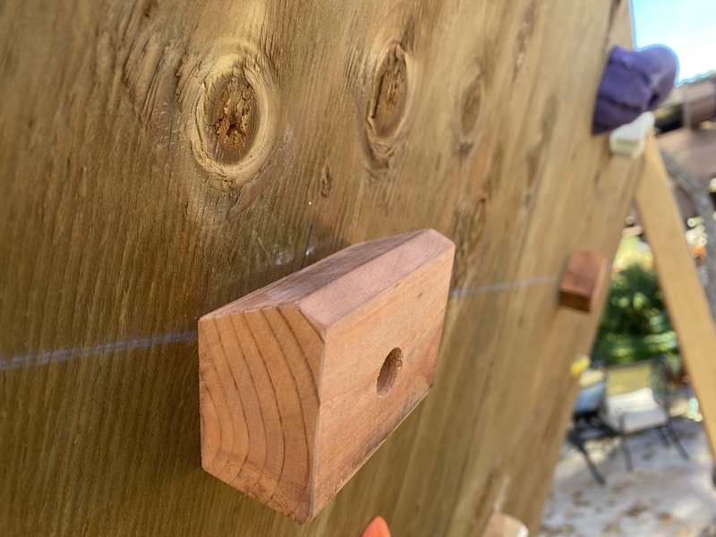
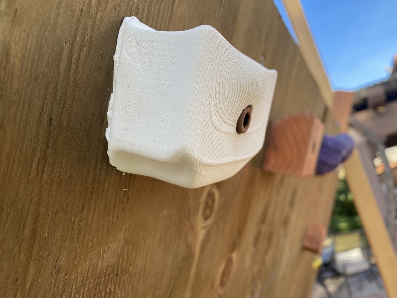
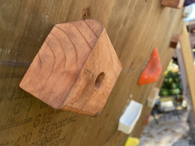
I made a few new holds using the miter saw cutting at an angle. I then made recesses for the bolts and sanded down all the edges. The wood has great look already so I didn't add any paint. Also I took a couple painted wood pieces and also put those up. These came out cooler though I think
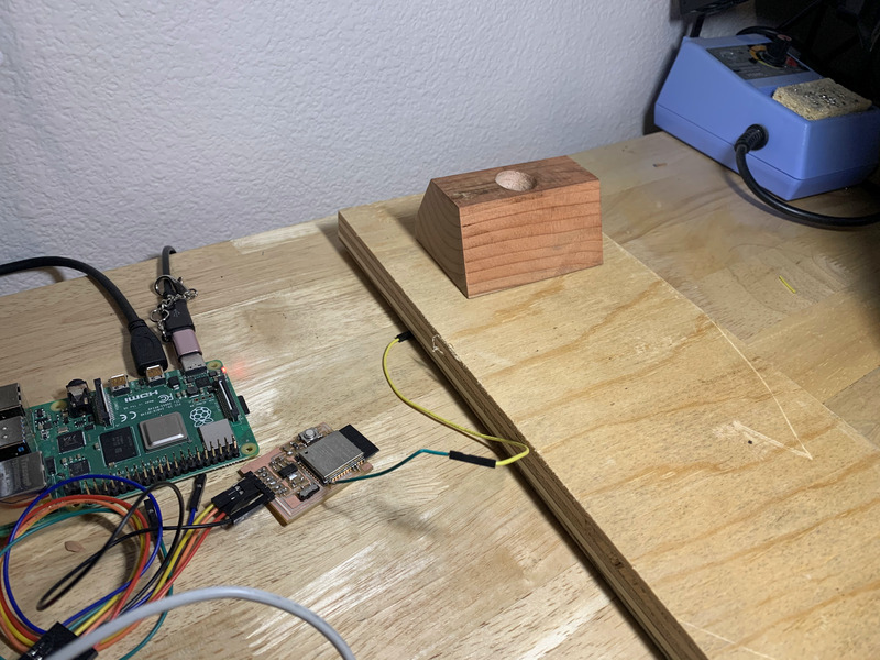
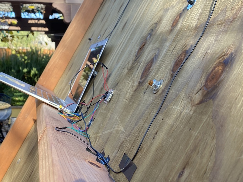
I went ahead and made a prototype on my desk and was able to read the values I wanted using capacitive sensing.
Now it's time test it on the wall!!! Here are a few pictures. I also added on some plastic ones I ordered online mostly because I wanted to try them out. Personally I think they're overrated and wayyyyy too expensive
Conclusion
Final One Minute Video
What Worked/Didn't?
The Wall Construction came out well. It also didn't take that long to ideate and was sturdy enough to hold me using supplies easily bought at a local hardware store.
The concrete holds that were too thin didn't work great; however, the concrete served to make them feel like real rock and the wooden holds were great regardless of thickness. The wooden holds were actually really nice and they are easier on my hands which is why they are so popular for training in the climbing community.
The ESP32 worked well and I was able to read decent capacitive values and upload them to my local server via the esp32 IP address at a decent rate.
Unfortunately I was not able to mill out a new board which would have made all of my connections much cleaner etc. The reason I was only able to show two holds operational is because I broke the leads off the pins for the the other capacitive sensing pins on the ESP32
How Was it Evaluated?

Future Steps & Considerations
Getting the ESP32 to modify a website paired with a database that can be remotely accessed and that has more features with a cleaner more professional look. The ability to login would most likely be desirable in this case as there would ostensibly be multiple systems.
I also would definitely like to mill out a new board to make every thing smoother. The board is already created, but would have to be milled.
Programming and outfitting the ESP32 to work with more than 4 capacitive sensors for personal use would be nice. An interesting consideration is how this could be scaled up to track hundreds of climbing holds (this would be relevant in a gym for example).
I wonder if it would be lucrative to install these in climbing gyms along with the server and metrics database?
Total Shopping List (I just paid for the wall build)
- Wall Build (Complete Shopping List Above): $250-$332.20
- Holds:
- Wooden Holds: (FREE, used scrapwood from Wall Build): $0
- Concrete: $10
- Oomoo (For molds): $20
- Thermoform Plastic (For mold): $20
- 3D Printer Plastic (For mold): $5
- Shop Time & use of Mill/3D Printer/Thermoform: ??? - $0 for me
- Holds Total: $55
- Electronics
- ESP32: ~$1
- 3.3 Linear Regulator (ZLDO1117G33TA): $.50
- Switches, capacitors, resistors, leds: $5
- PCB Board: $5
- FTDI USB to Serial connector: $6
- Shop Time & use of pcb mill and soldering iron: ??? - $0 for me
- Electronics Total: $17.50
- Grand Total: $322.50-404.5