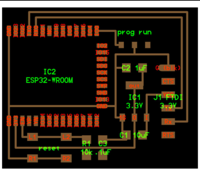
This week I decided to use the ESP32. Here's my journey to getting it up and running. NOTE: I used the pcb mill traces and client code found on on our class site under ESP32. (Neil wrote this code)
Still trying to find the best way to solder. The ESP32 was difficult because the spacing is so small. I think it may be better to place solder down on all the pads first and then use the heat gun to go ahead and melt the solder.
Also putting solder on one pad first to fix components in place is definitely the way to go.
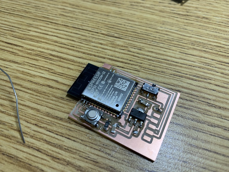
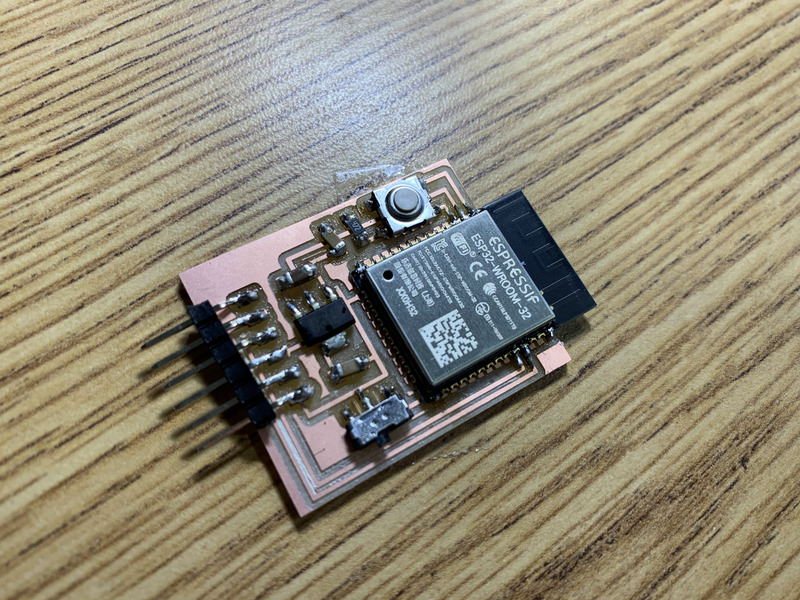
I made sure to make sure everything was visually okay and there weren't any shorts I could detect. I then went ahead and used the code that Neil provided on the HTMA site linked in my about page for a client esp32
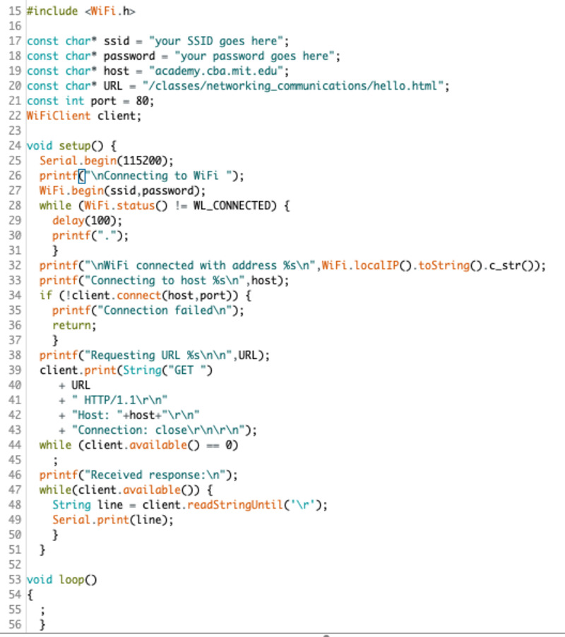
I used this link to get the board into the Arduino IDE: https://dronebotworkshop.com/esp32-intro/
I needed to go to add a json file to the preferences file and add the ESP32 board using the board manager under tools. I used the ESP32 by Espressif Systems
For board I selected the ESP32 Dev module
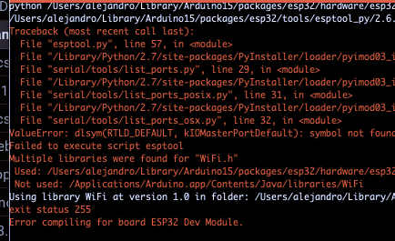
I tried to compile and upload using my mac, but I kept getting the error below when I was just trying to compile. I tried deleting some libraries and updating some of the files and combing through stack overflow. I think the issue is I recently updated my mac.
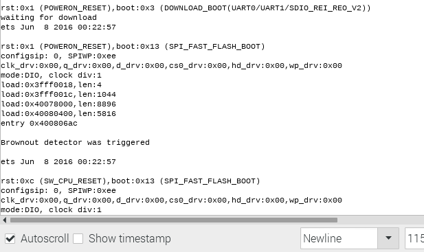
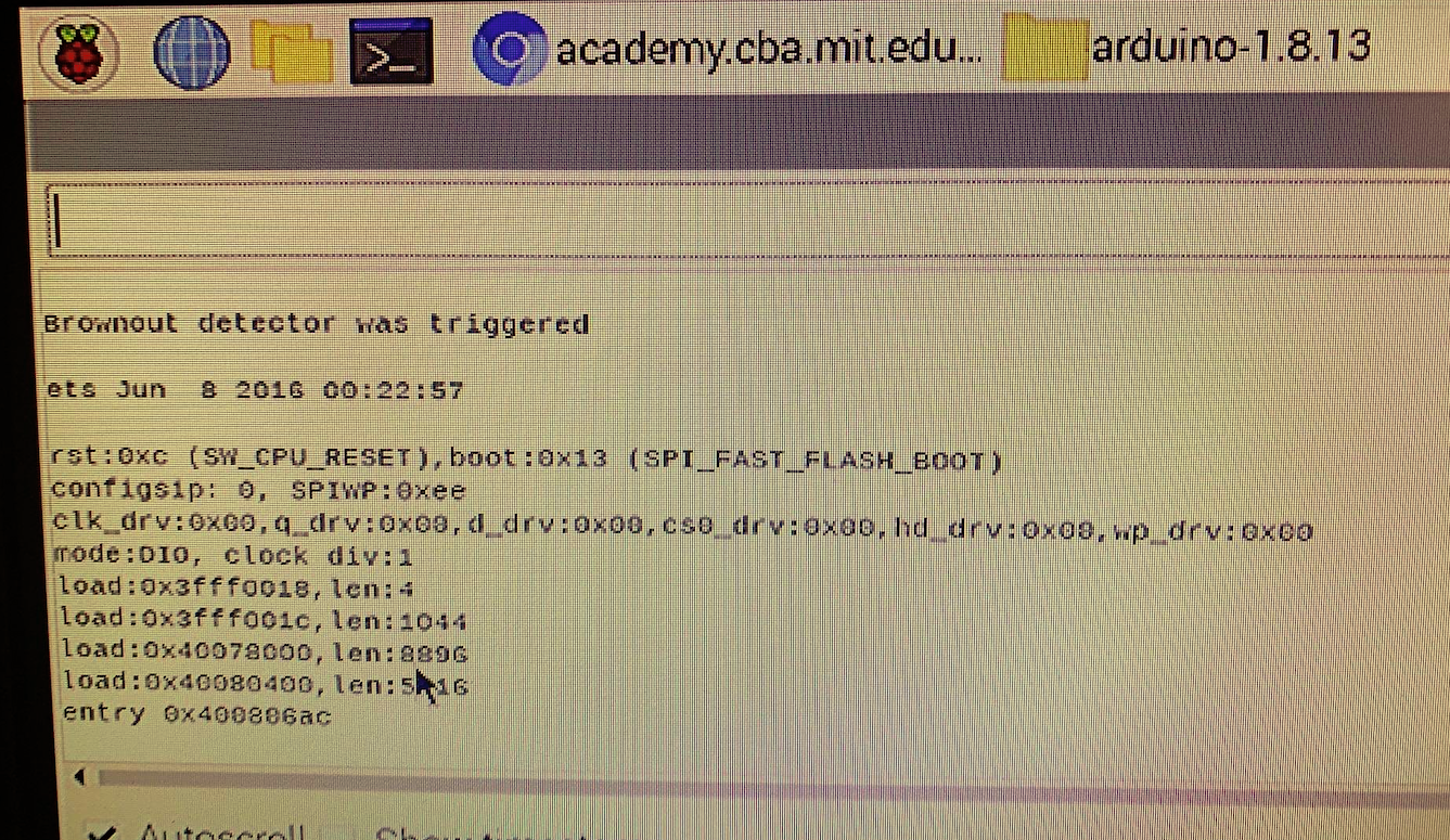
In order to get around this issue I just turned to using my raspberrypi and I was able to get it to compile and upload! But then I got this message below when trying to run the program. Debugging never stops!!!
I was still getting this error so I figured that the error came from a lack of current/voltage. I read the incoming FTDI chip voltage and it was 3.2V so I thought that might be insufficient
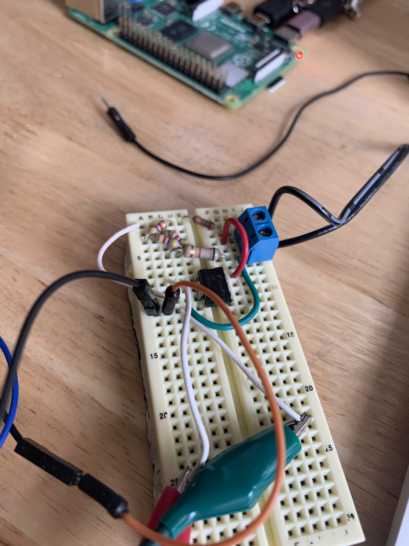
I decided to make a voltage follower op amp setup using an outlet power source and a voltage divider. I set it up to output 3.4V
However, even when I ran this the voltage still dropped heavily as if the chip was drawing a lot of power and the voltage ended up at 2.6V which is too low.
Then I had my aha moment. Premila asked me if I was inputting 5v via the FTDI and I realized that there is a jumper on the ftdi chip in order to have it output 5V instead of 3.3v. This fixed my problem!!!!! I probably also could have set my op amp setup to output a higher voltage than 3.4V and that also would have worked.
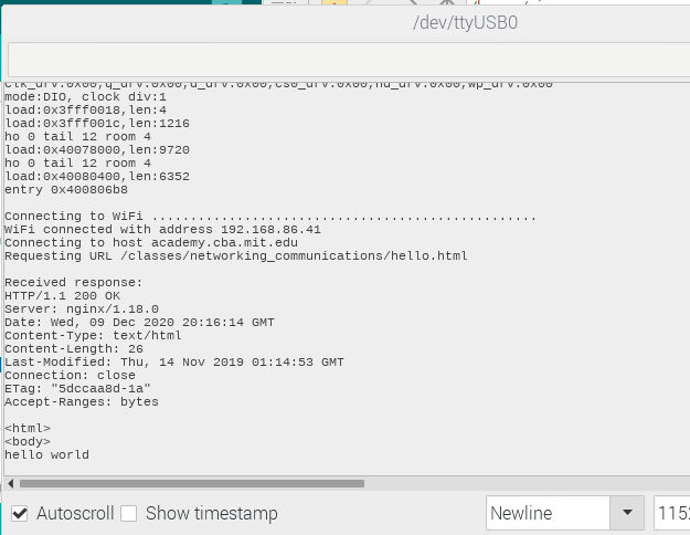
Success!!!!!! I got the esp32 to read off of a website and then print it out to the Serial terminal!! For more on what I did with the esp32 look at WEEK 11 and my FINAL page.