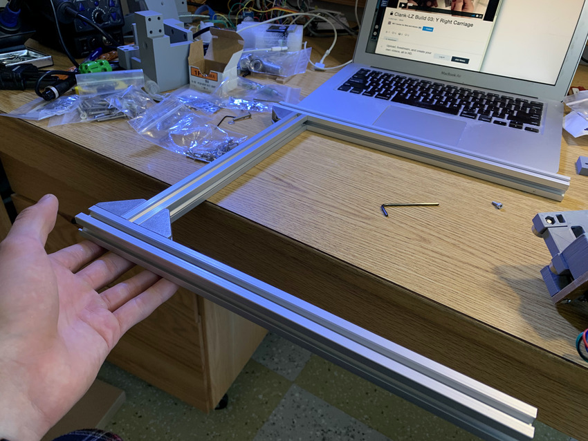
Frame Build: This one was pretty straight forward. Just slotted all the sides together and made sure they were fairly level.
The screwdriver was too big and I ended up stripping a motor screw, but I got a friend's that was sized perfectly and was able to get it out. Not the biggext problem though because you can mount it using the other diagonal. You just can't strip more than one.
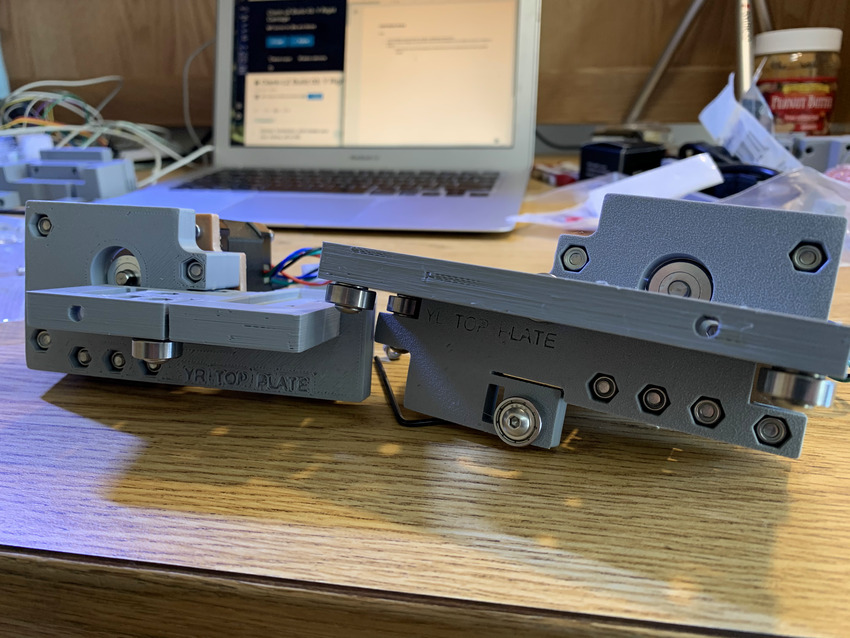
Then I went ahead and made both the X and Y sides.
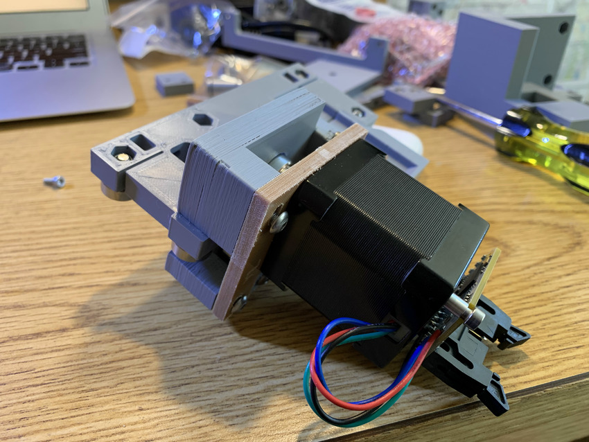
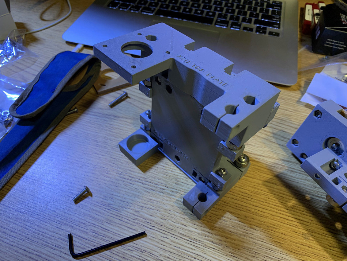
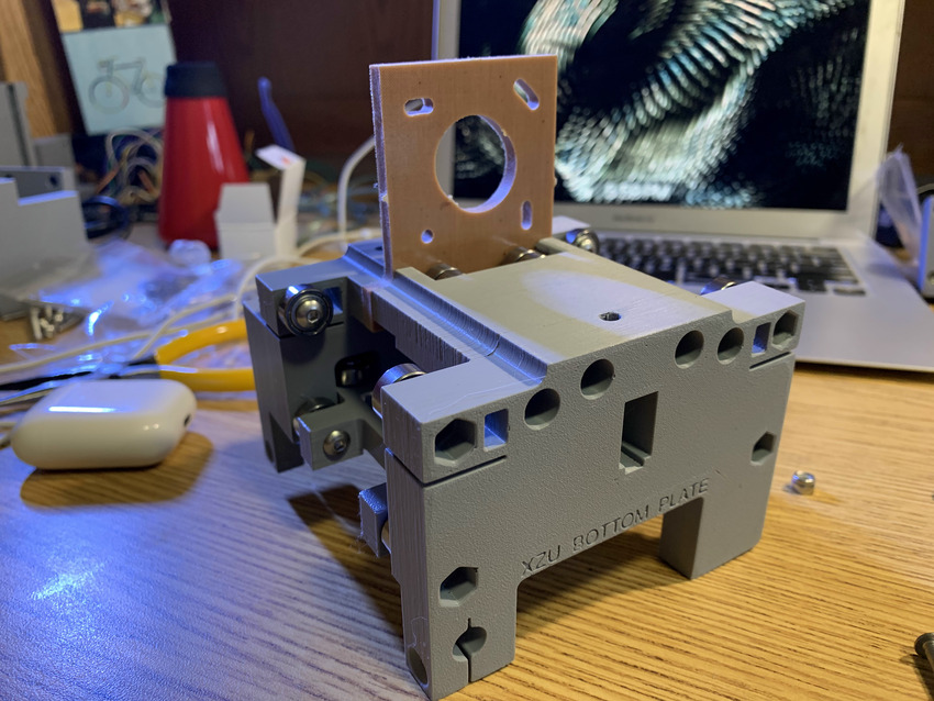
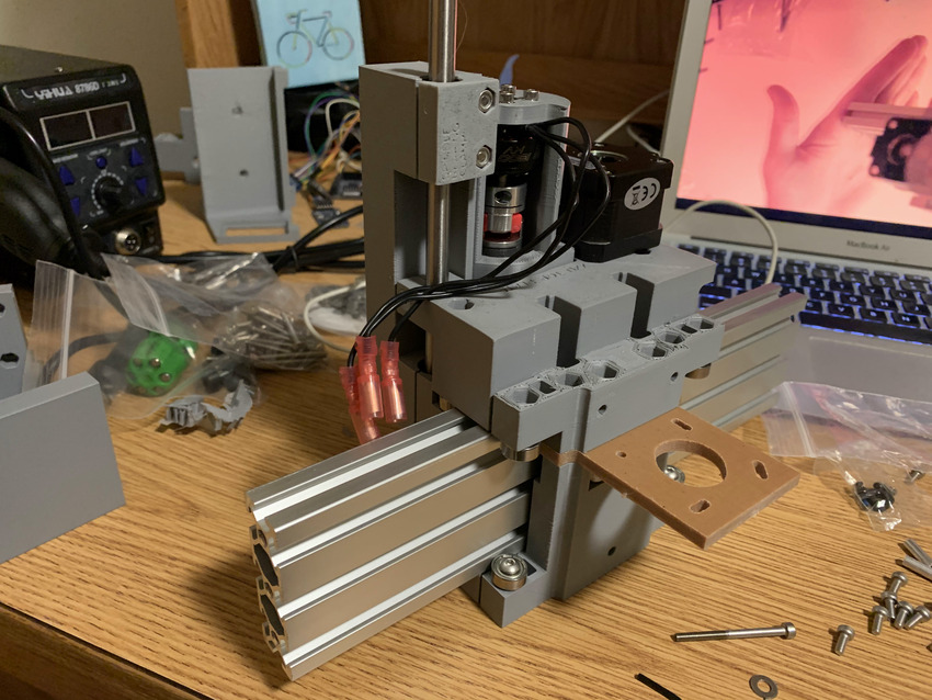
Next up was the spindle and z motor carriage build. This was definitely the trickiest section. Some of the washers and bearings barely fit in.
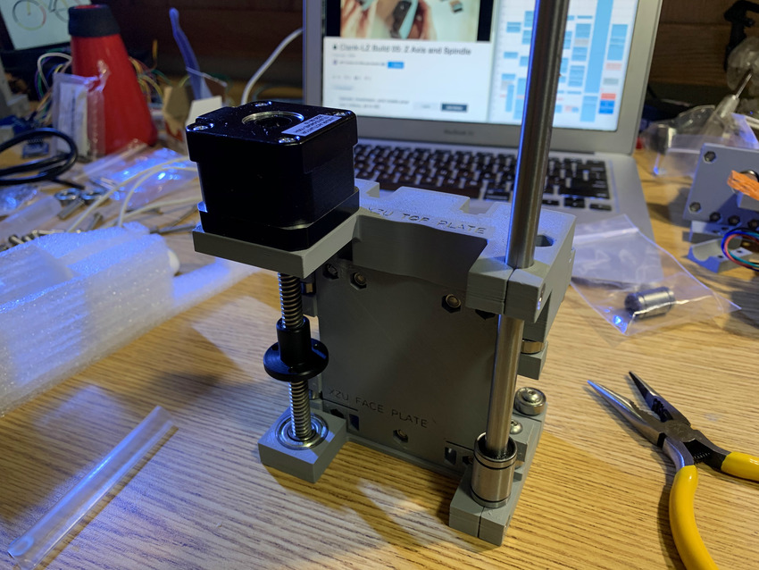
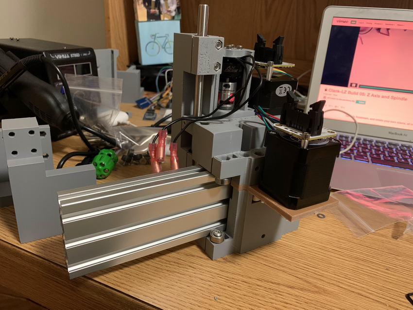
I added in the z motor to complete the Z and spindle build
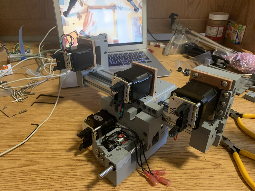
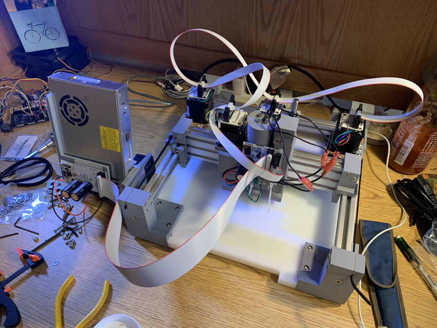
After combining all the pieces the mechanical part of the pcb mill was done!
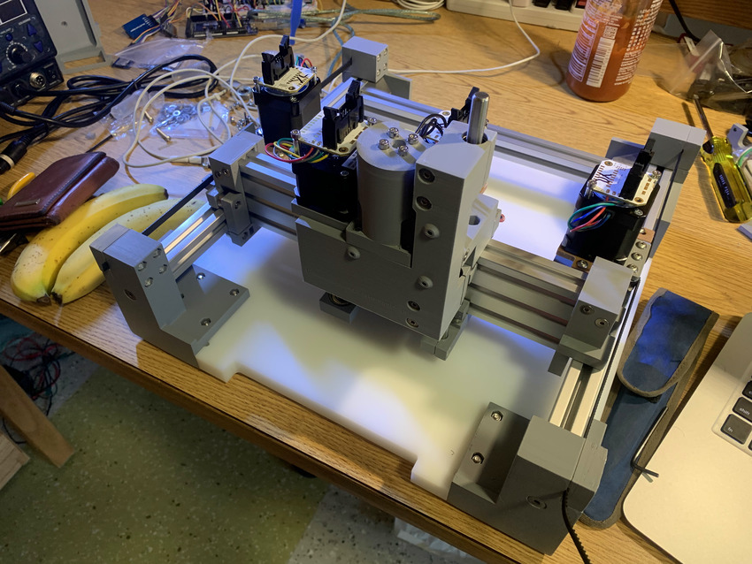
Then I wired everything up. I had to be careful the wires attached to the motors could freely move about in all directions and locations for the mill as it's moving about. However, after flashing the software it wasn't working so I had a long session with Jake Read to try to figure it out.
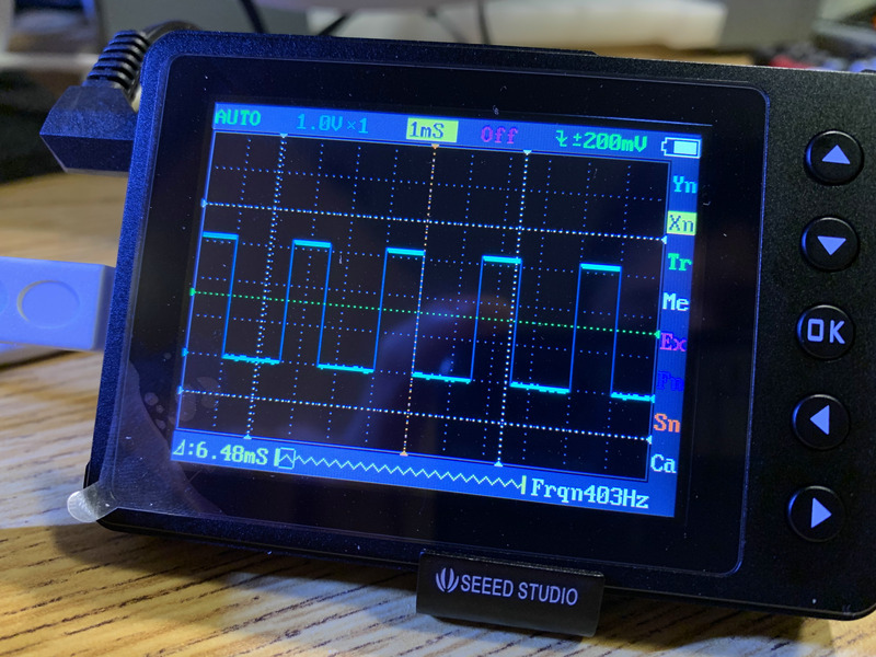
In summary my spindle motor wasn't turning, so I used my pocket oscilloscope to measure the output of the PWM wave from the motor. Turns out I had flashed the wrong code and therefore, wasn't working. I had to make sure the connections and hardware were working though. On the bright side I got to use the oscilloscope!
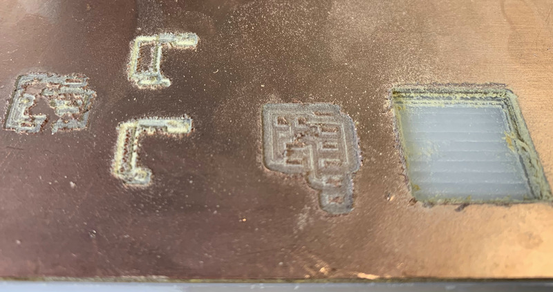
Here we have some of the videos of the facing and of the milling process for the programmer. I wasn't able to mill the programmer until the following week.
My biggest complaint is that I didn't understand how to create g code to cut out the pcb, so intead I just did multiple individual passes of about .2mm depth to cut out the outline. This worked, but took a while and required a lot tedious small changes. However, it came together and the soldering wasn't too bad (I have some experience soldering).
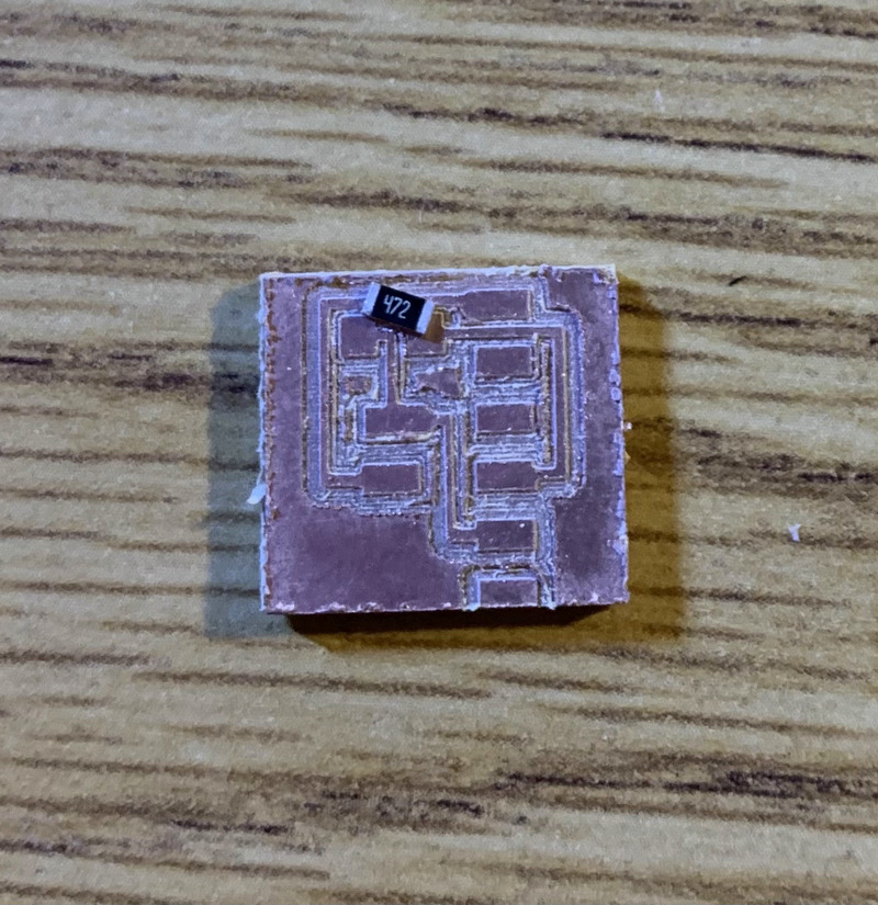
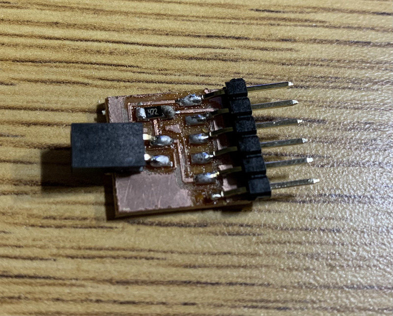
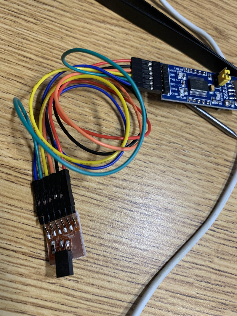
Here is the programmer hooked up to the FTDI cable. DISCLAIMER: at this point they were hooked up incorrectly. Also if you're wondering why the quality of cut is so bad I didn't realize until later that my spindle direction was wrong.