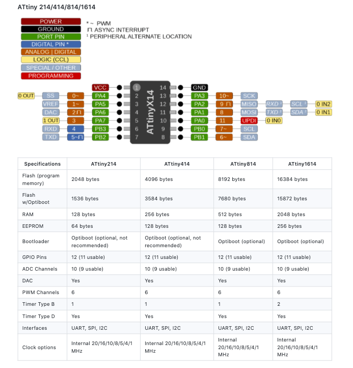
For the ATTINY 1614 pinout see the picture below and the link for that info is here.
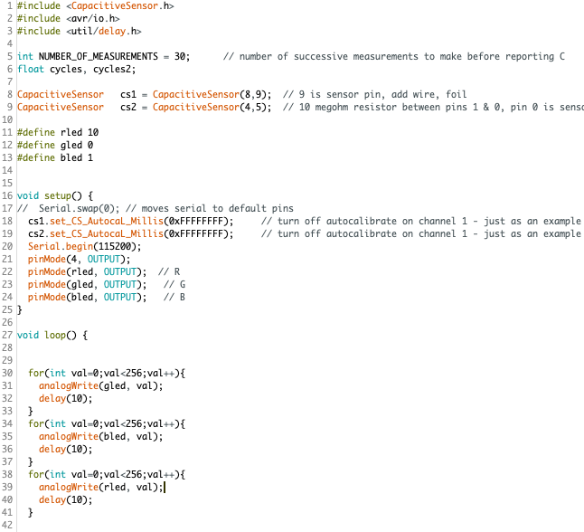
I run this to upload my code
python3 pyupdi.py -d tiny412 -c /dev/tty.usbserial-AR0K4XLQ -b 57600 -f ~/Documents/Arduino/build/HTMAtest.ino.hex -v
You can run the following to look at all your ports
> ls /dev
I run this to talk to my Arduino over UPDI
python3 -m serial.tools.miniterm /dev/tty.usbserial-AR0K4XLQ 115200
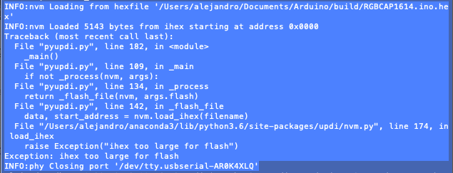
Thankfully this time with the 1614 I won't run into memory problems, which should make things easier
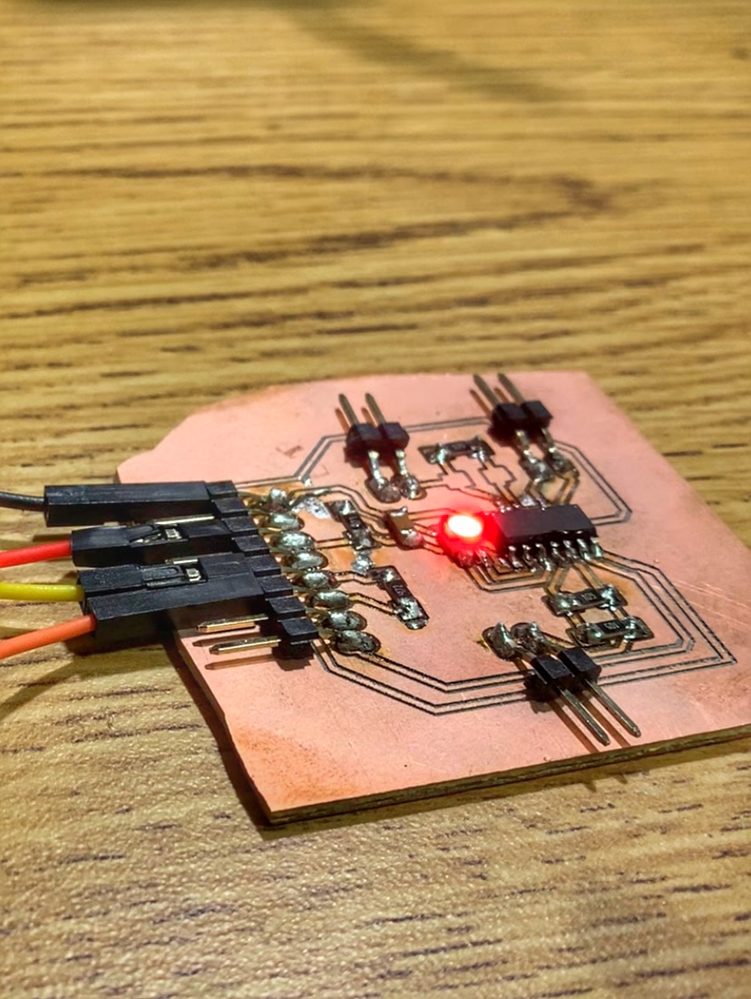
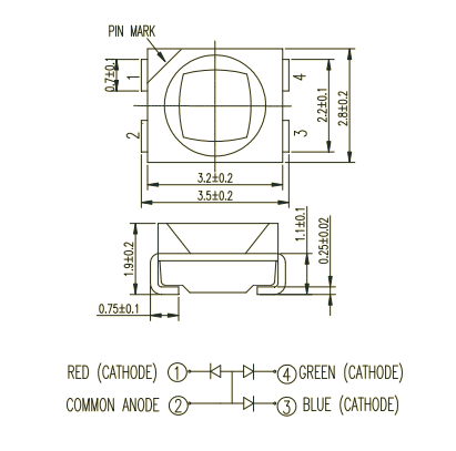
Using an RGB LED this week so had to pull up the technical document to look at the diagram and make sure that I soldered it in right
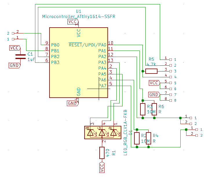
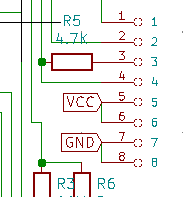
Tx pin from the USB to Serial goes across the 4.7k resistor on pin 3 below. Pin 4 is RX. Pin 1 is TX, Pin 2 is RX for communicating with the computer, so just move the TX/RX lines two up when you want to do so
When programming: "Serial.swap(1) or Serial.swap(0) will set the the mapping to the alternate (1) or default (0) pins."