Final Project
Final video
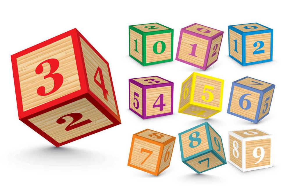
Concept: I study cognitive development, so I think a lot about how kids learn and whether the toys we surround them with really support their learning or not (not that they all have to). The toy that grinds my gears the most are number blocks. They're everywhere, and they make NO SENSE. The way kids learn that 2 is more than 1 and 3 is more than 2 is a slow process. They learn the count list (saying 1,2,3,4,5,etc.) just like they'd learn another song where they have no idea what the words mean. But the jump to understanding that as you move up the count list means you add one more item to a set comes much later. First, they learn what 1 means and can hand you a single item, but if you ask for 2 they give you a handful. Then slowly they can give you 2 but 3 is still a mystery. This goes on until they reach 4 or 5 and then they have an a-ha moment where it all falls into place and they understand the "cardinal principle" that the count list refers to increases in a counted set. All that to say that a single block that has the number 3 on it makes absolutely zero sense if you're trying to get your child to understand how numbers work. So my idea is to make a set of blocks that snap or magnetize together, with small e-ink screens on top that will change the number depending on how many are attached, so children can add or subtract blocks and see the numbers change based on how many are connected.
Skills used: Procreate, Fusion 360
These give me the shivers.
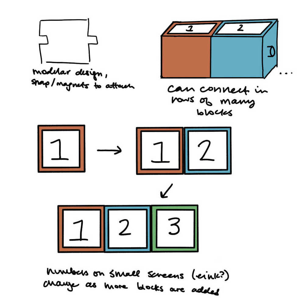
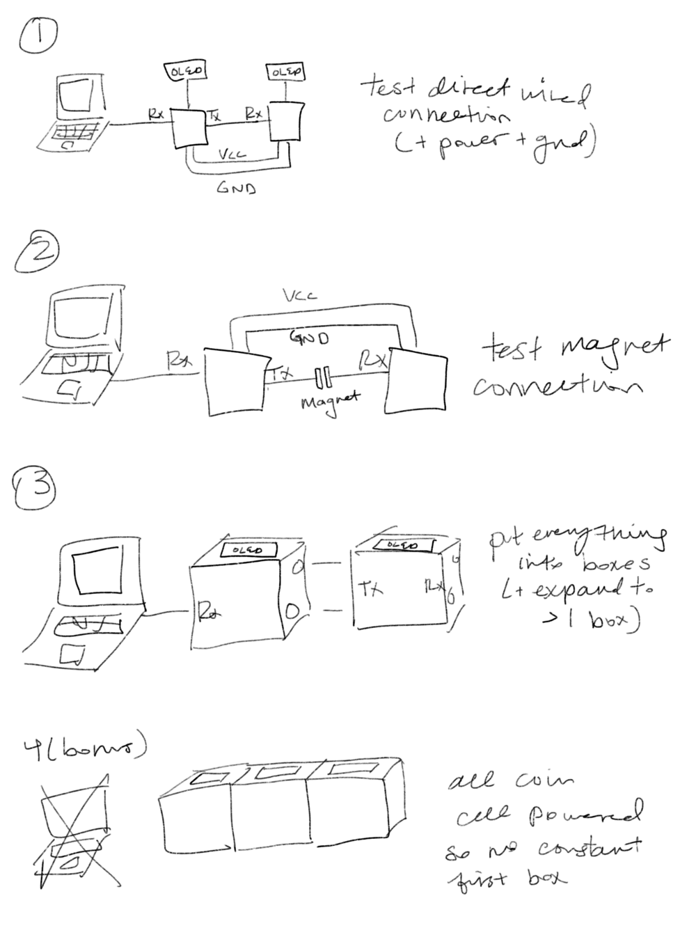
A sketch of the idea - the number on the screen should be in counting order depending on the number of blocks it's connected to. It would also be fun to be able to add function blocks so older kids can use them to practice addition, multiplication, etc.
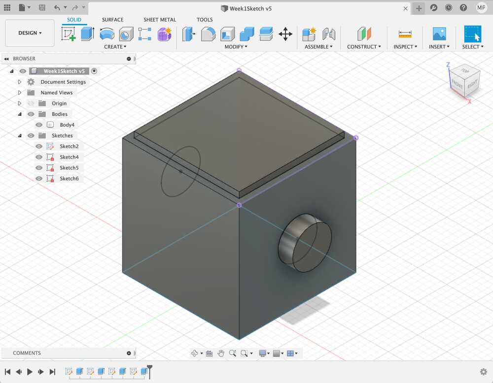
My first fusion sketch! It was more intuitive than I expected, and I practiced using parameters to adjust the shape and size of the block and the connectors.
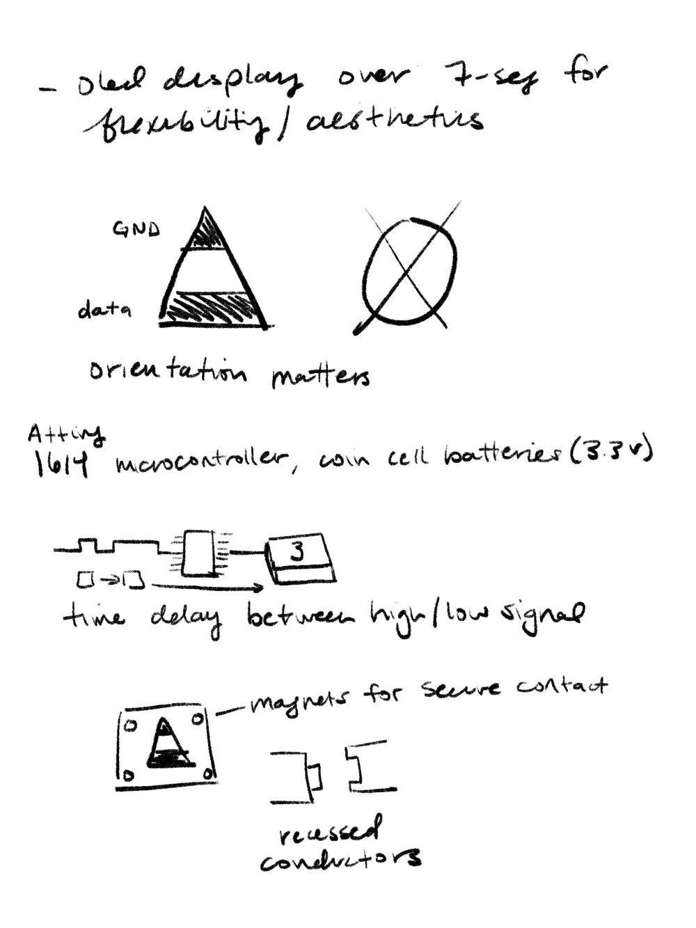
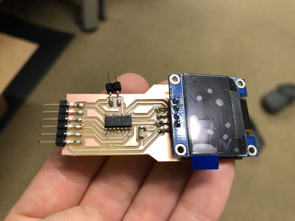
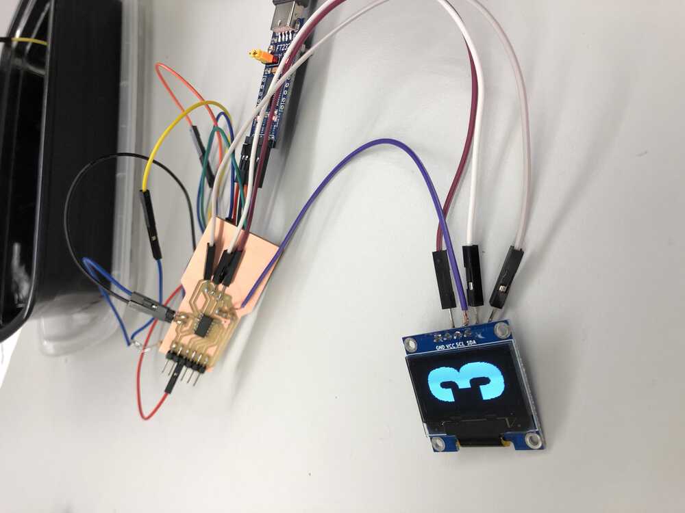
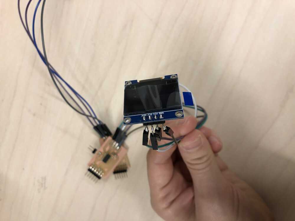
UPDATE: Getting OLED Display working - this is what I'll use to show the numbers on the screen of each block.
I'm slowly starting to feel more confident about electronics design, so this design/cut/stuff/program process went much more smoothly than the past few weeks, except for a small hiccup in the footprint design for the OLED (explained below).
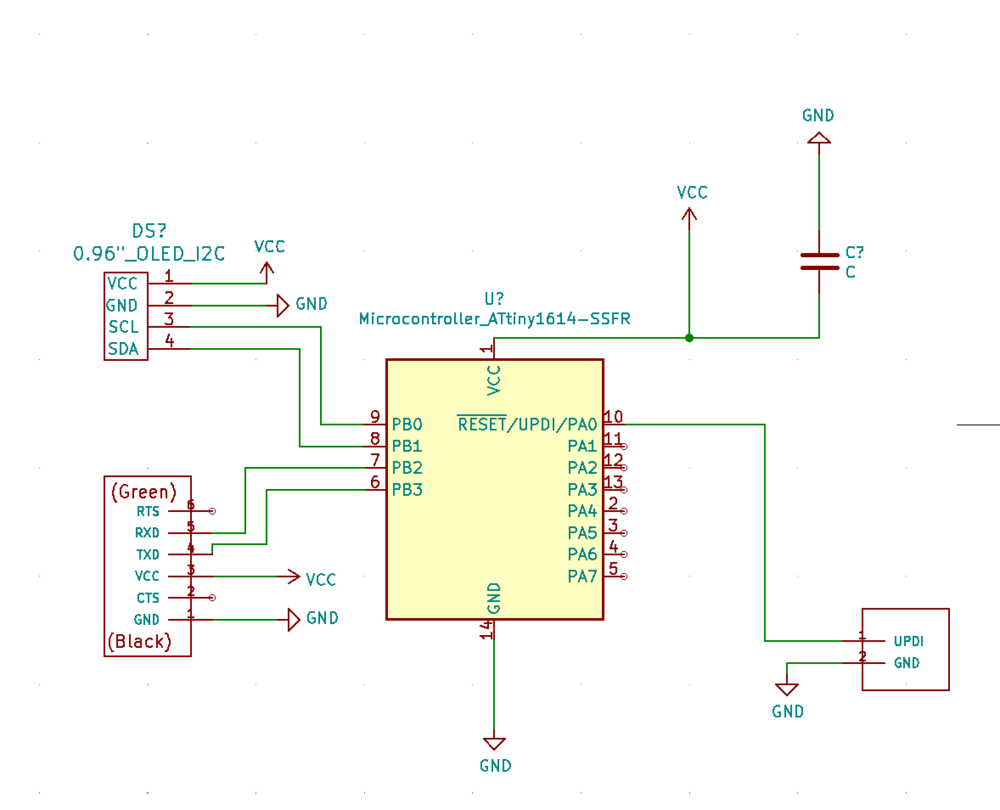
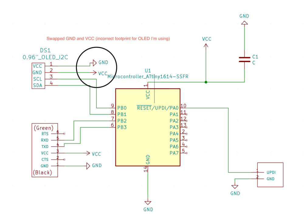
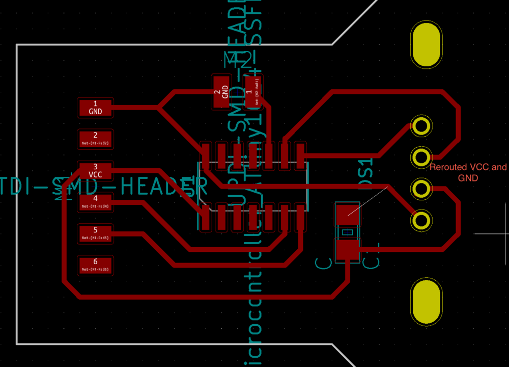
I started with a schematic - I had used the 1614 tiny in my week 7 project, so I was familiar with the pinout for that, and it all went smoothly until I realized that I didn't have the schematic or footprint info for the OLED display. I did a little digging and found a prior student's site where he had created a footprint library for the OLED I was using. (Site Here) *IMPORTANT NOTE* Be warned, the VCC and GND pins are reversed on this footprint, so don't do what I did and have to reroute them!!!
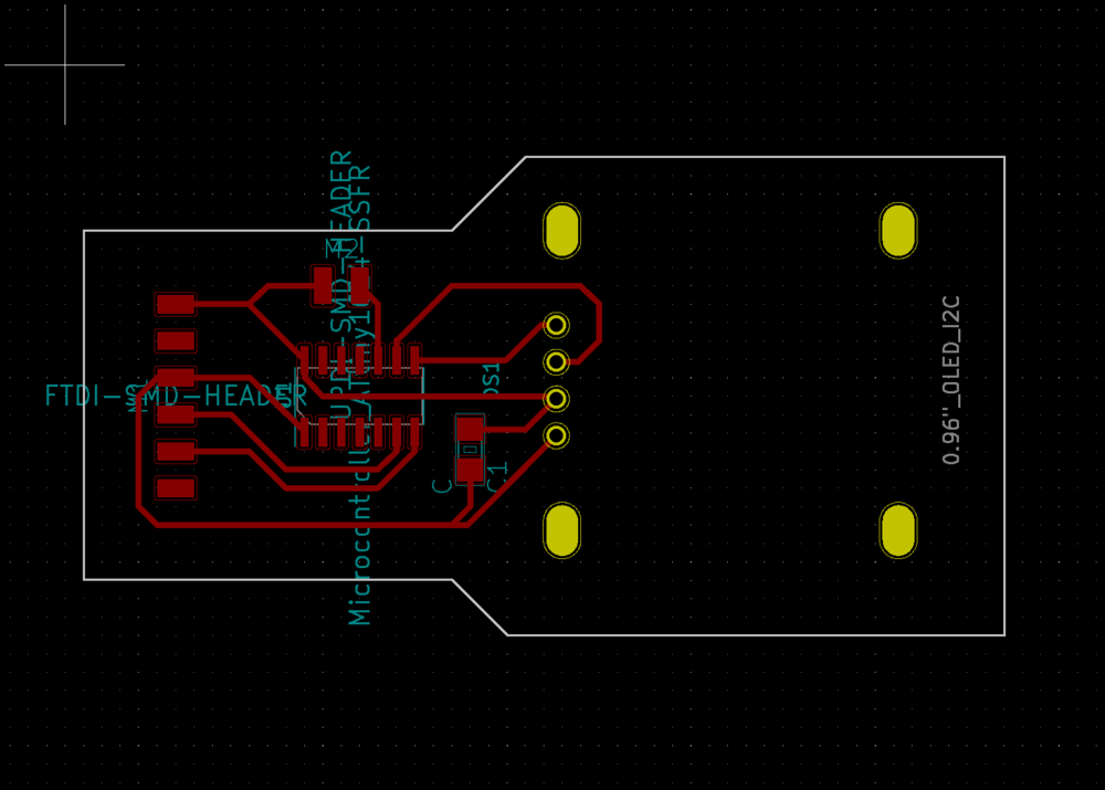
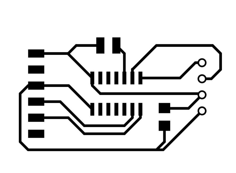
The footprint made holes for the display but I just wanted a steady surface to solder it to, so I changed them from open holes to closed squares in Illustrator.
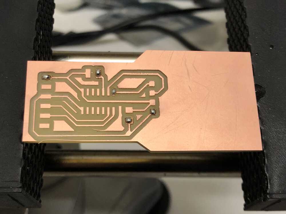
Board cut on the clank - it's working reliably now as long as I tighten the top screws before each cut.
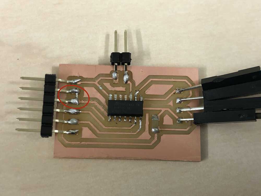
Here is how I originally soldered the board before Anthony helped me realize that the VCC and GND pins were switched
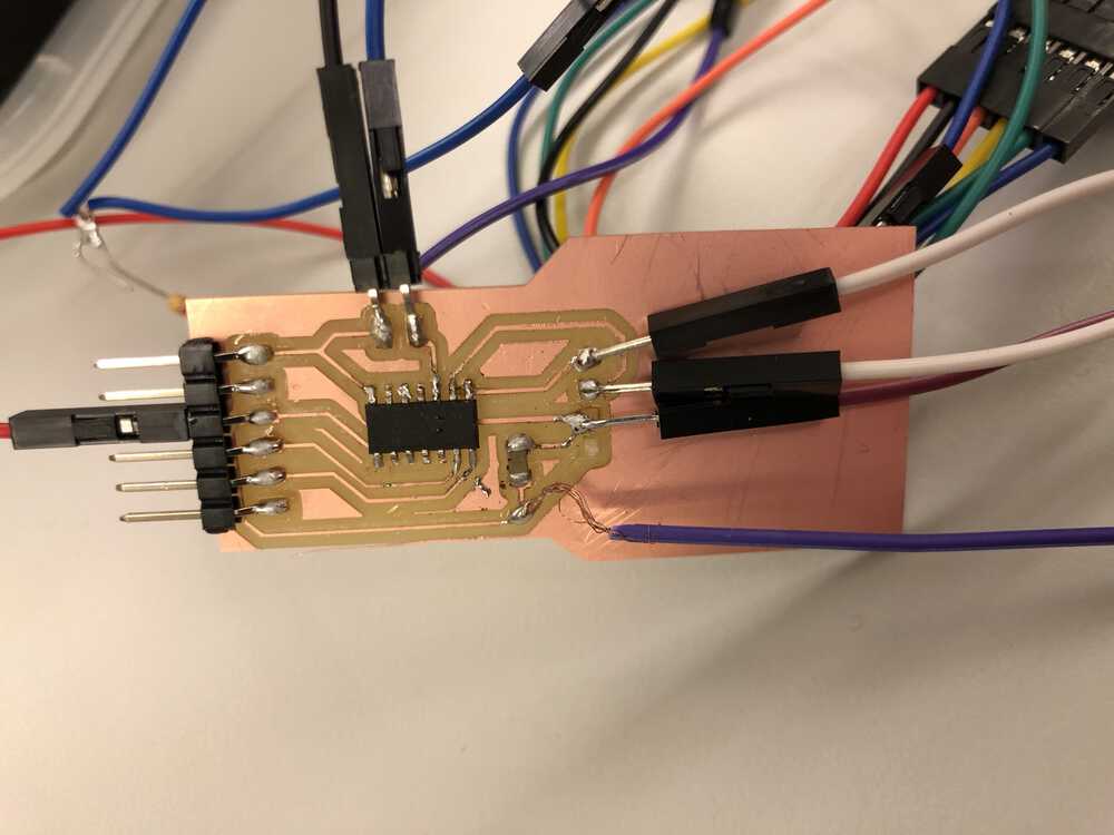
And after the slightly janky job I did in rerouting...
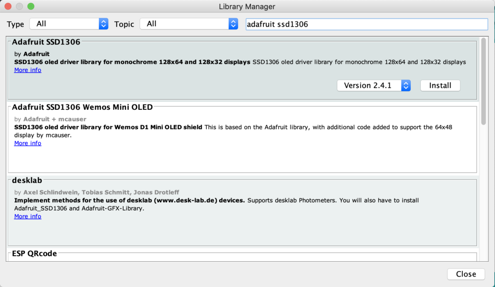
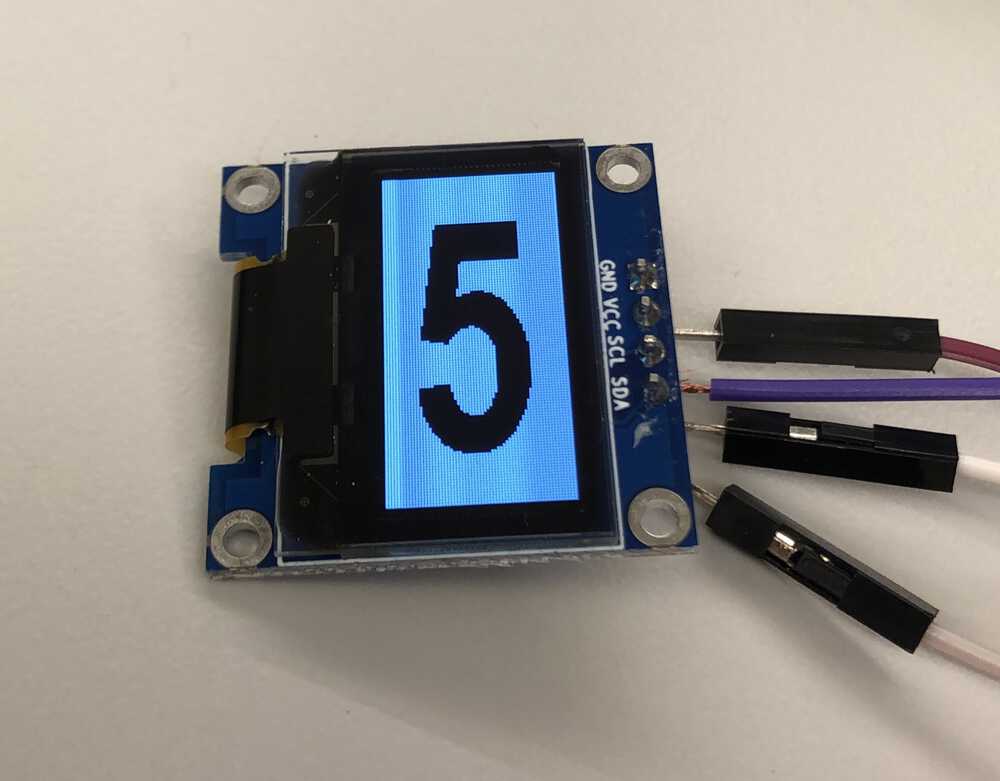
I then installed the Arduino graphics library that you can use to talk to this type of OLED, and Created a bitmap of a few numbers to test
A few sample images below!
I'm currently working on incorporating a finger joint box design with a taper that can make the boxes fit closely together enough for contact to be made between each box. And I'm hoping that the network/communication lecture will help me better understand the best way to communicate between the devices.
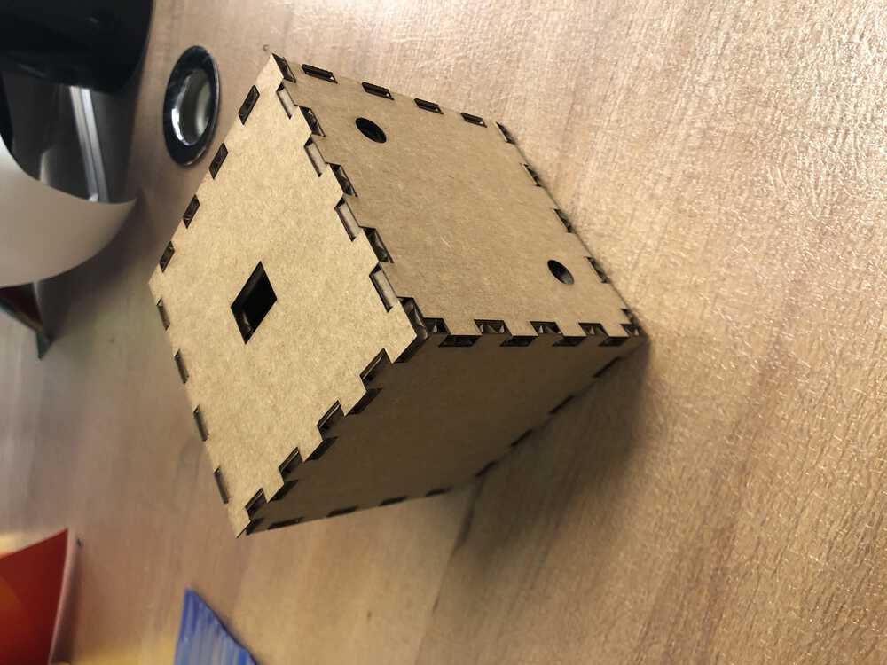
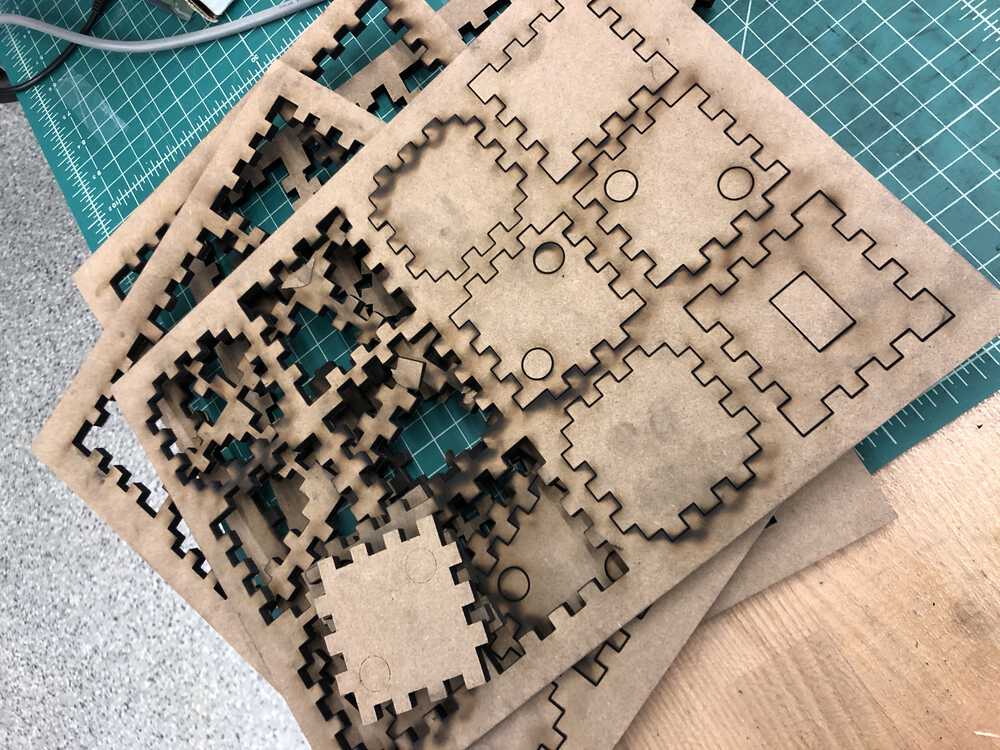
UPDATE before Thanksgiving: Laser cutting boxes!
For my project I need a box for each circuit board to live in, with spaces for magnets to connect the boxes and create connections between the microcontrollers so they can create a network and display the right number on their OLED. I ended up using some MDF which I thought would make a sturdy box and would support the magnets and be paintable to look kid-friendly. Unfortunately it was a nightmare to cut through...
I started with a cardboard version to test things, but the screen looked too small in a box that big so I adjust things for the final version.
I had to do a handful of test cuts with the MDF because the preset options weren't strong enough to get through this horrid material - the true thickness was 0.25 inches but I had to up it to 0.35 to get it to make it through to the other side.
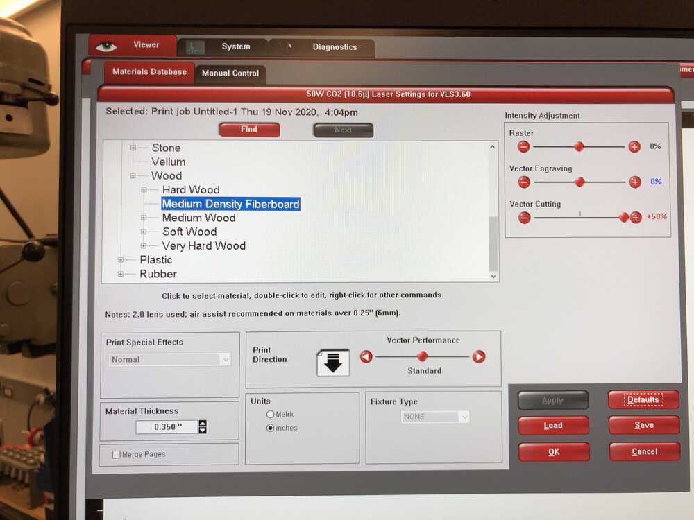
Even with that I had to do two cuts on some of them to get them to separate, which led to a very gross sooty situation.
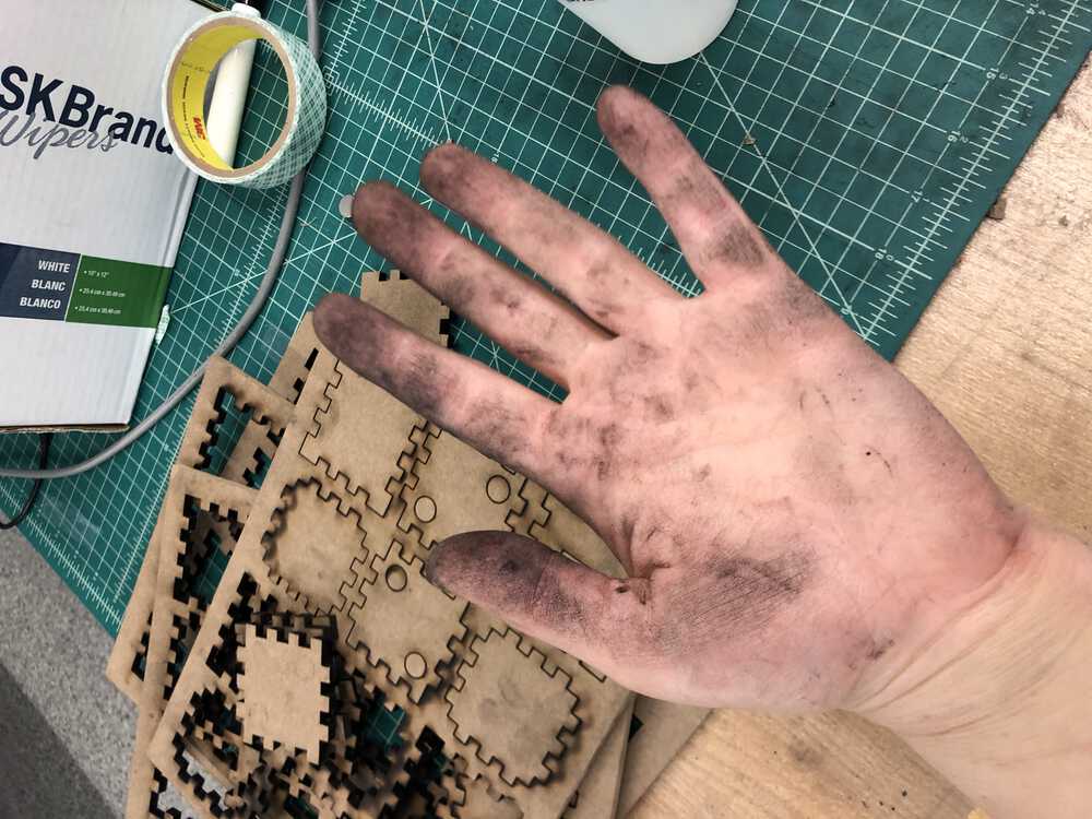
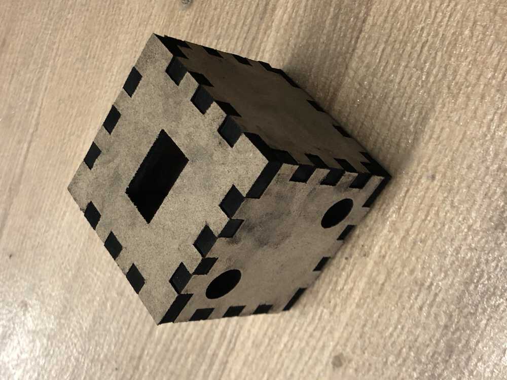
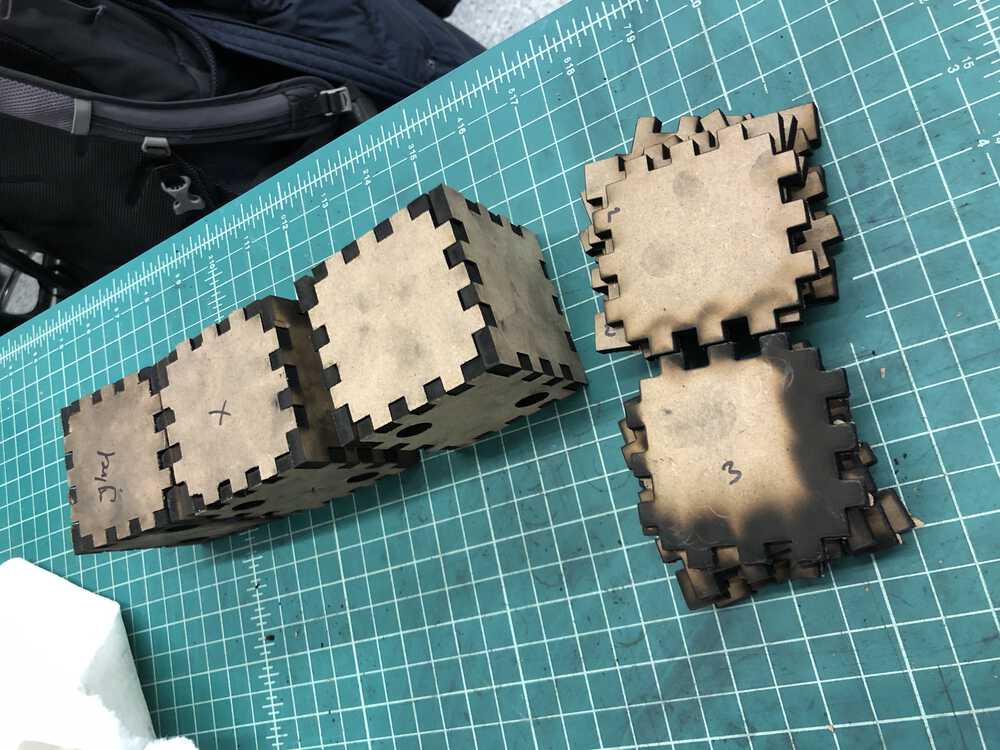
After a good amount of suffering, I ended up with enough usable boxes, but I'm glad I made the decision to paint because they look like they were barely saved from a campfire.
UPDATE Dec 1: Plan for final steps towards final project
There are a few important steps left for my final project:;
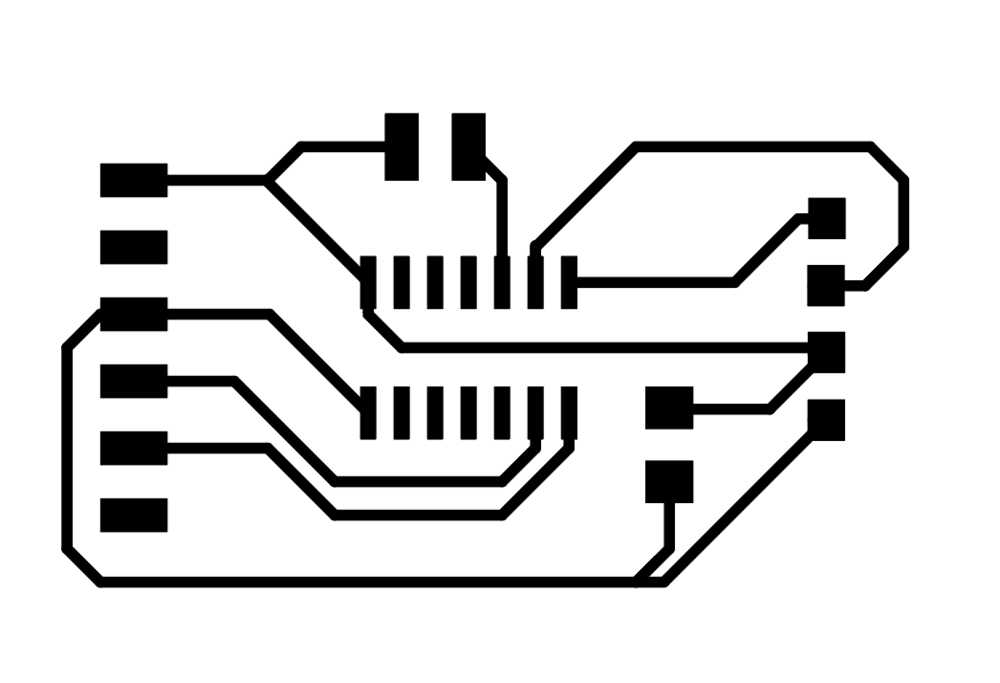
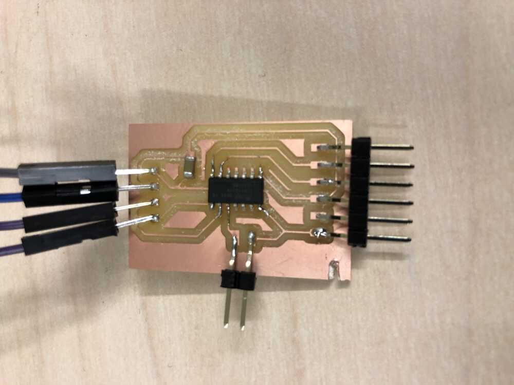
I started by updating my OLED circuit board from last week to fix the swapped VCC and GND pins
I cut and stuffed two boards with this new layout, and am working on the program for them to communicate
Update Dec 9 after networking week
I started by cutting another board from output week so I had two identical boards connected to OLEDs. Ideally I want all of the blocks to be interchangeable so I want both the boards and the code on each to be identical. I also updated the code so that it output text instead of bitmaps, because I was overloading the 1614 when I tried to load an image for each of the numbers. I'll play more with this next week.

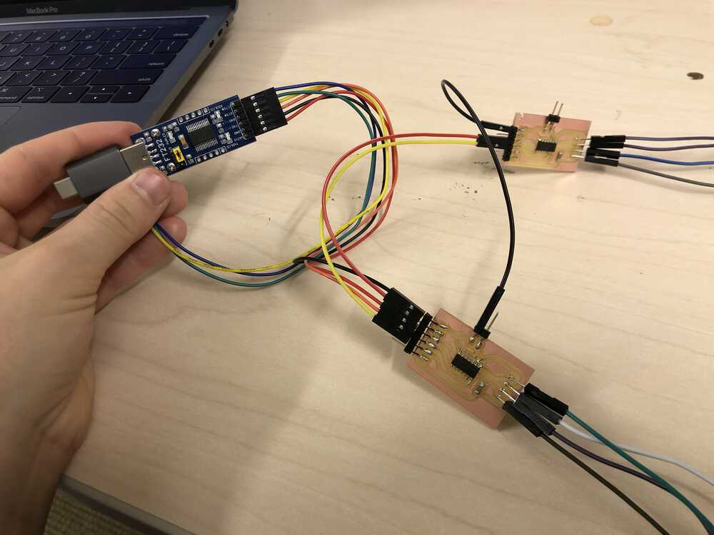
After milling the boards, I worked on the arduino code (here) so that each board would take in a number input from the serial port and then show that number on the OLED, and then pass n+1 back to the serial port. Here it is being tested on the serial monitor, whereas eventually it'll be output to the next board in the chain.
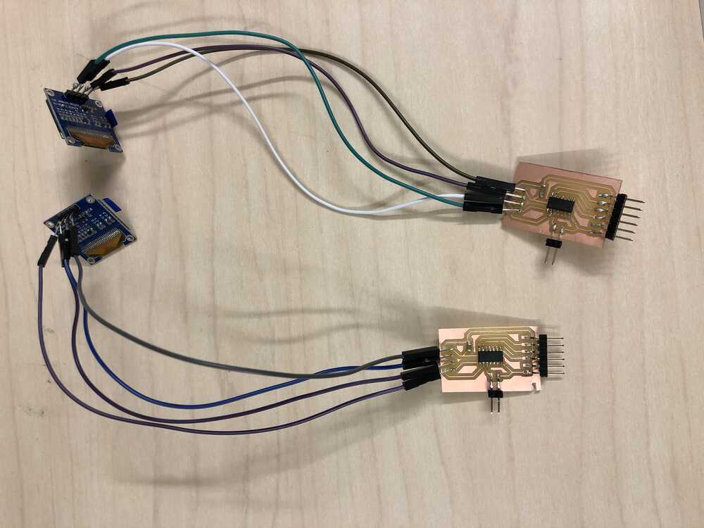
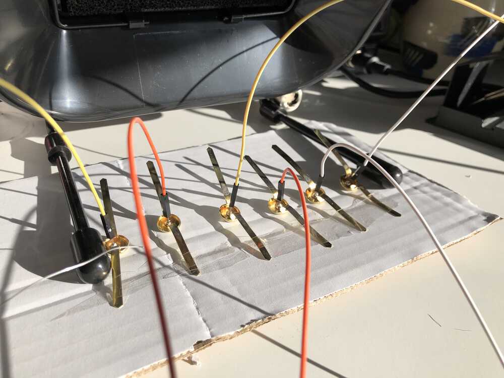
After I got that working, I connected the first board so that it read in from the computer, and with it's Tx output going to the Rx of the next board instead of back into the usb connection. It was at this point I realized I had a place to connect ground and Tx/Rx between each board, but I didn't have a way to connect power - but I soldered a little bridge across two of the pinouts and that solved the problem.
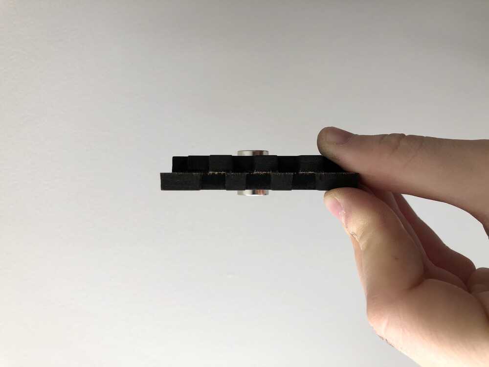
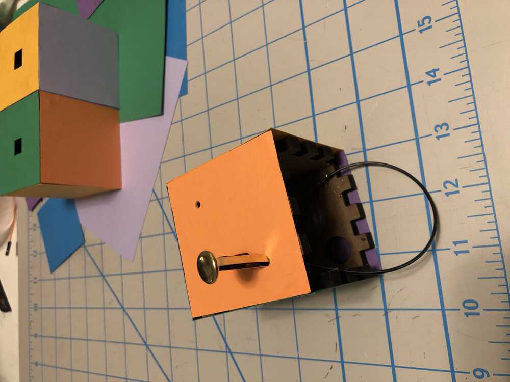
So things were working well when wired directly, but for the boxes to be interchangeable I wanted them to be free-floating so I wanted to test out some different connections. I ended up finding some brass fasteners in my office that soldered well and have a handy little bendy end so I think they'll be nice to use inside the box. They're also magnetic so I'll work on using those together to make a reliable connection between boxes. But for now here's a test to show that the fasteners work to form the connection!
Final update
The last thing to do was to put everything into the boxes and finalize the connections.
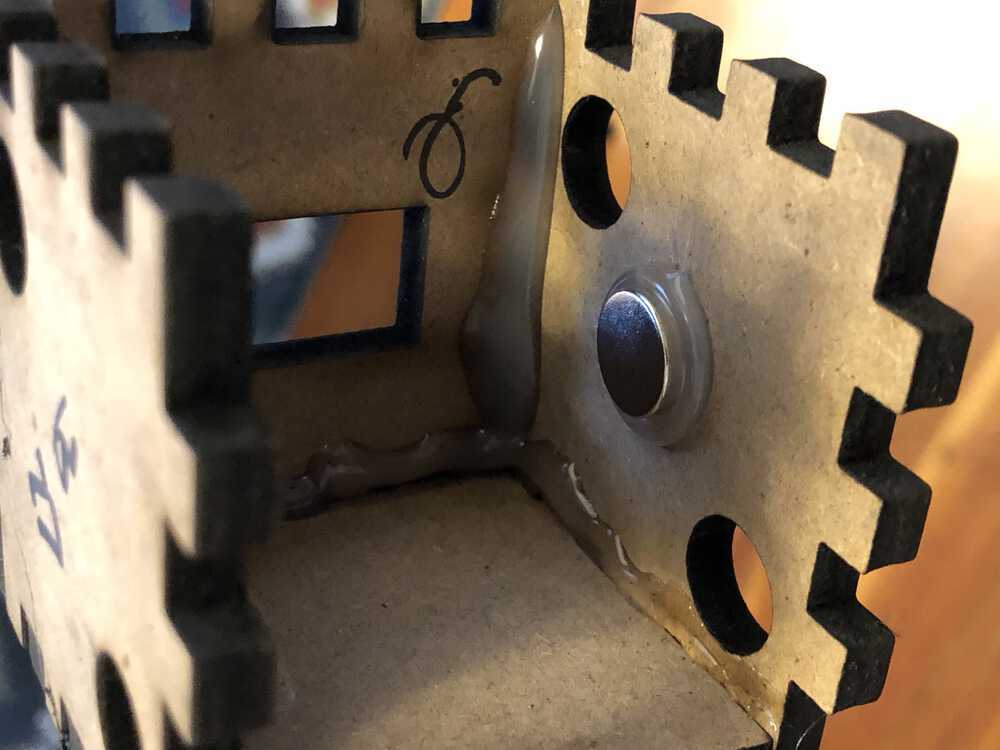
When the magnets were used against each other they were so strong that I would never want to give it to a kid because it would be too hard to pull apart and might pinch their hand, so I did some tests and realized that a magnet inside each box was enough to draw them together and make a good connection but it was still easy to manipulate them.
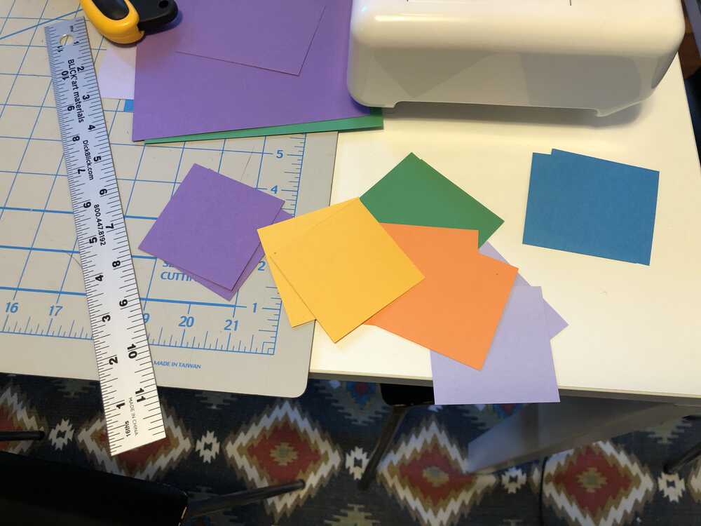
My mdf was burnt to a crisp and it was really dusty so my original plan of painting didn't seem like it would work very well, so I went with a covering of cardstock. If I had lab access I would've recut the boxes with colorful acrylic but I made do with what I had in my personal crafting arsenal.
Even though it is the opposite of technical I really like the feature of using brass fasteners as the connectors - I think they look pretty sleek and it's a fun unexpected application.
So happy and proud!!!
Reflections:
What does it do? I designed a set of blocks that can help kids learn the mapping from their count list onto physical sets of objects, which is one of the biggest conceptual leaps in early math learning. Each block has a small screen that shows its identity in relation to the set, and has connections on either side to communicate with other blocks nearby.
Who's done what beforehand? I haven't seen something like this, but there are other toys out there that are modular in nature and communicate between them - e.g. blinks from move38
What did you design? What parts and systems were made? What processes were used? I designed the board around an Attiny1614 microcontroller using Kicad, cut the board on Clank, soldered on the components, and used the arduino Wire library and the Adafruit GFX library to communicate with the OLED display. I designed the blocks in Fusion360 and cut them on the laser cutter, and designed a way to use brass fasteners as the wireless connectors between blocks.
What materials and components were used? Where did they come from? How much did they cost?
| Part | Source | Price |
|---|---|---|
| PEMENOL 5PCS OLED Display Module | https://www.amazon.com/PEMENOL-Display-0-96inch-Raspberry-Microcontroller/dp/B07VL7F27P | $22.99 |
| Attiny 1614 x 3 | Digikey | $0.67 |
| Medium Density Fiberboard 0.3" thickness | Lab trash pile | Should have been paid to use it |
| 1UF Capacitors x 3 | Digi-key | $0.07 |
| Brass fasteners | Staples | $3.00 |
| Single side pcb stock | Global Laminates | $1.40 (bulk price) |
What questions were answered? My biggest question going in was how the boxes would communicate with each other. I at first thought I would need to come up with a way for them to take electrical pulses and then modify them to send to the next block and wasn't sure how to make that process reliable, but it turned out that it worked well to just daisy-chain the input (Rx) - output (Tx) ports of each box and have them send digital signals that way.
What worked? What didn't? I'm really happy with how things turned out, I think I was successful in the main goals of the project, although I think the finishing could be better and I wish I had used acrylic rather than the MDF that I had to cover in paper because it doesn't seem like it would hold up to real play, but overall I think it's a good first prototype of my idea!
How was it evaluated? My goal was to make each block be able to sense where it was in a set and show that number on the screen, and it does that well! I also had a "stretch" goal of making each block completely independent (not needing to have one tethered to the computer) and I'm really happy that I ended up having time to get that done.
What are the implications? I've solved early math learning! Not really, but I do think that this idea would be fun to share with kids and educators because I think it has the potential to really impact kids' understanding of this concept so I want to think about how best to do that.