final project: electronics design
November 8, 2020
Given two viable options, I plan on implementing and experimenting with both the solenoid and stepper motor. I will design the PCBs that will activate these two output devices with a button press. This will give me much-needed experience working with the solenoid and stepper motor which will be necessary for the final project.
solenoid
Like I noted before, I wanted to design a PCB that would activate a solenoid with a button press. I am planning on using the ESP32 for my final project, but I decided to use the ATtiny412 for this board since I only need a couple of pins. Like the other PCBs I made with the ATtiny412, I needed to create a UPDI connector to program my board. I also connected the associated FTDI pins to the ATtiny412 pins.
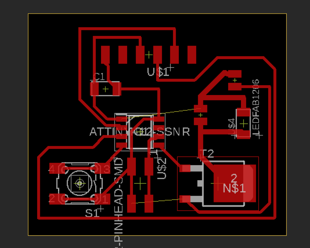
One note is that there is a significant inductive load when the solenoid is turned off. Therefore I need to attach a diode from the end of the solenoid back to the beginning of the solenoid. This will transfer the magnetic energy to the diode instead of breaking down the MOSFET. I also used the large N-channel MOSFET to play it safe.
Lastly, my stepper motor and solenoid need to get enough current/power to work well, so I am using a 9V battery to power the launcher, however, I will use the computer’s power to power my ATtiny412. Because we will be passing in much more current into the solenoid, I was advised by Anthony to increase the width of my traces from 16mm to 30mm for the traces that would carry current from the battery.
Below is my board design for my button triggered solenoid.
My solenoid board
Since I went into the lab to confirm my boards would be fine, I decided to use the Othermill to mill the PCB. This process went smoothly and my PCB turned out nice.
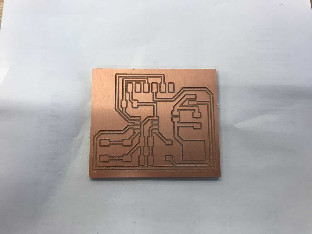
Traces of my solenoid board
After I grabbed all of my components I started to solder. Soldering the large MOSFET was a challenge as there was a large connector on the back of the MOSFET, so I put a good amount of solder on the trace and used a heat gun to ensure the MOSFET was in place. The traces to solder the battery connector as well as the solenoid were both smaller than I expected. This made it hard to solder them onto the board, however, I was able to get them soldered.
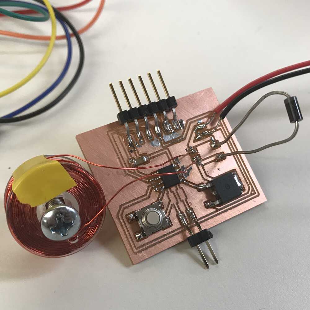
My soldered solenoid board
Now that my PCB was complete, it was time to upload some code and test to see if my board worked properly. I first started by writing some code that would echo back the current state of the button (which should change when the button was pressed). This worked so I knew my board could be programmed.
I now wanted to activate the solenoid when the button was pressed. This meant I needed to set the pin that was connected to the MOSFET to be high so my solenoid would activate. However, when I programmed my board and plugged in the 9V battery, the solenoid was always activated despite the button printing out the correct state. This was odd because I used the multimeter to probe the pin and the voltage was changing. After trying new MOSFETs, new ATtinys, and re-soldering, I couldn’t find a solution to my problem.
Luckily Anthony came and saved the day. After looking at my board, my MOSFET was not connected to the ground from the FTDI but the 0V side of the battery. This was the problem, so I soldered a wire from FTDI ground to the ground I was connecting the MOSFET to, and it worked!
The code I used is below.
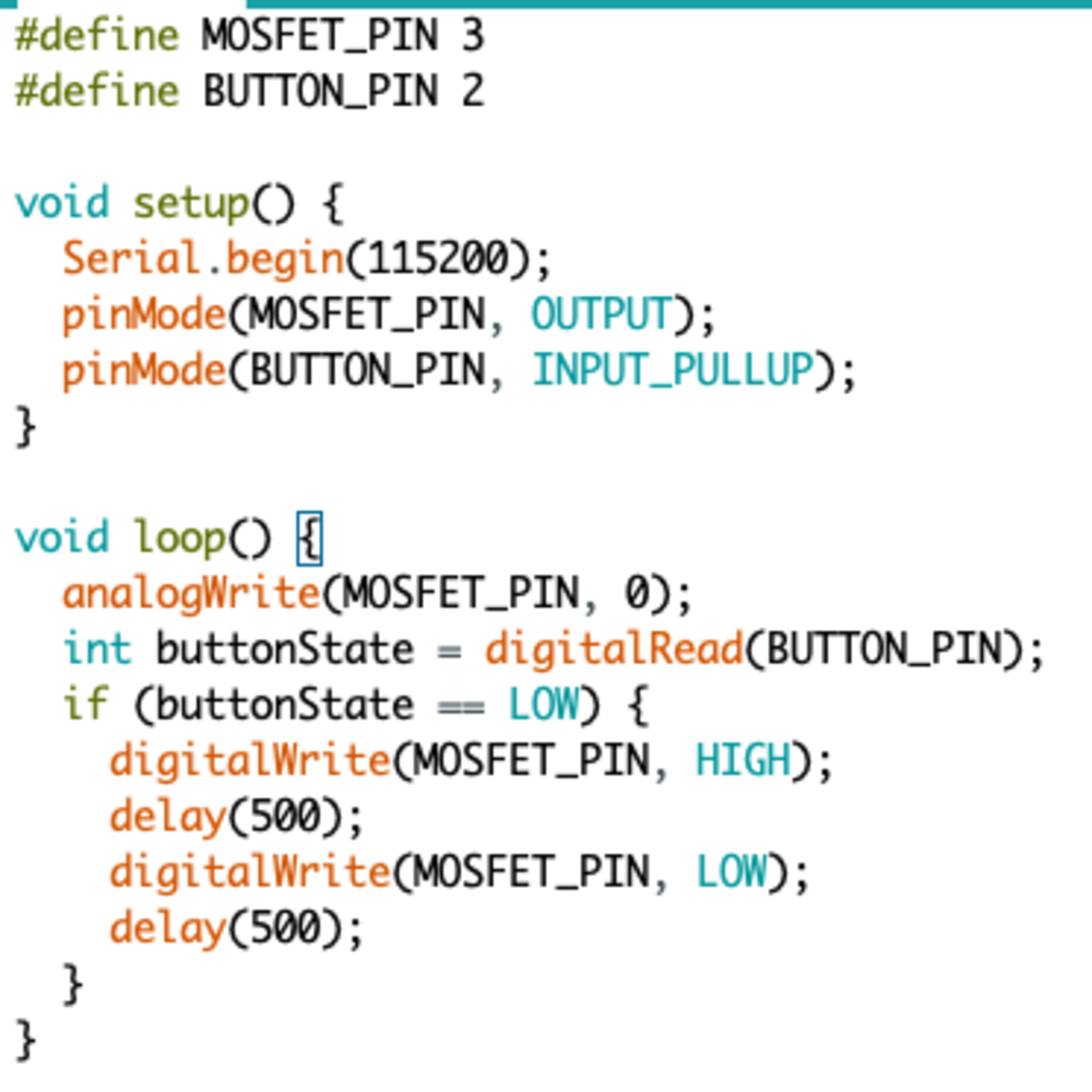
Code to launch treat with button press
Solenoid launching a treat
stepper motor
The electronic design for the stepper motor was a little more complicated. We had to use H-bridges to control the bipolar stepper motor I planned to use. Again, I plan on using a 9V battery to power my stepper motor and the power from my computer to power the ATtiny1614. One thing I need to consider is how I will power my final project. I am leaning towards getting a wall adapter and using voltage regulators to distribute the desired voltage to my motors and processors. I will do some more thought on how much voltage I’ll need and the different voltage regulators I’ll use.
But like my last design, I added a UDPI connector, a button and the battery. I added two H-bridges (each H-bridge accepts two inputs and gives two outputs) and these H-bridges will control when my stepper motor is activated. I had a tough time finding a place to connect the VCC to the H-bridges. I could have used a 0 Ohm resistor to jump over some traces, however I just decided it would be easier to add a wire to jump some of the traces. After I solved that problem I had my board all designed and ready to cut on the Othermill.
But like my last design, I added a UDPI connector, a button and the battery. I added two H-bridges (each H-bridge accepts two inputs and gives two outputs) and these H-bridges will control when my stepper motor is activated. I had a tough time finding a place to connect the VCC to the H-bridges. I could have used a 0 Ohm resistor to jump over some traces, however I just decided it would be easier to add a wire to jump some of the traces. After I solved that problem I had my board all designed and ready to cut on the Othermill.
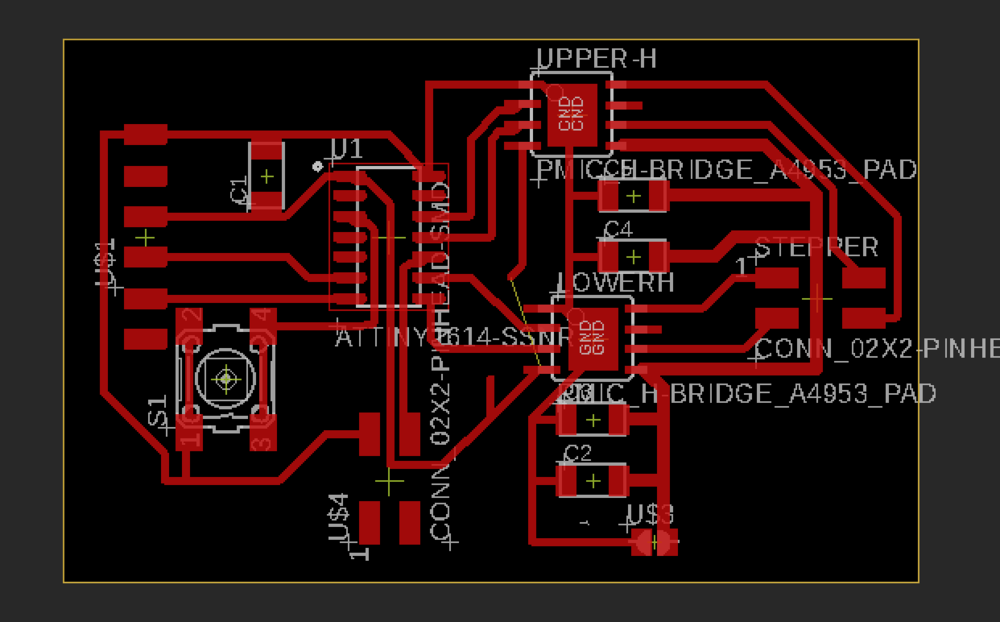
Stepper motor board
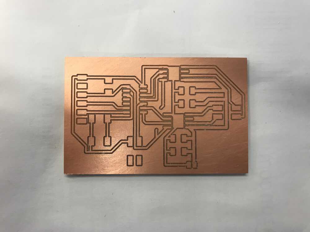
Stepper motor board traces
I started to solder all of the components of my board and I didn’t run into any problems. Here is the final result of my board.
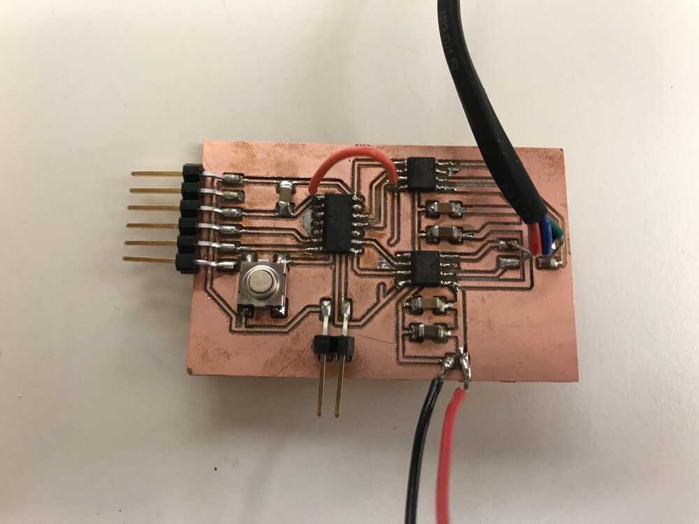
Stepper motor board after soldering
I followed the same process as before and wanted to test that my PCB was working and could be programmed properly. Luckily this worked!
Now I had to get the stepper motor to work. Since my stepper motor would make a full rotation for my dropping device, I wanted to program the stepper motor to make one full rotation. To see the position of my stepper motor, I added some tape to help visualize the motion of my stepper.
However, after some deliberation and testing with Anthony and Premila, I wasn’t able to debug my stepper. I used both the Stepper.h library as well as manually setting the pins to be high and low to try to get my stepper to move. I used the multimeter to probe the pins and the H-bridges and things seemed to be fine. I also was able to lock the stepper motor in place which was odd since I couldn’t get it spinning.
Luckily, Anthony was able to debug the stepper motor and saw that the coil resistance of the stepper is low enough that the H-bridge detects the coil as a short and doesn’t apply power. He tested this by running a resistor in series with the coil and it worked! However the resistor burnt up, so he decided to use a power resistor which ended up working. These got pretty warm when in use, however for my final project my stepper motor will only be on for a short period of time. Therefore this solution should be fine for now. He also ordered some stepper drivers to hopefully solve the issue if the power resistors don’t end up working nicely.

Code to spin the stepper motor one full rotation
I figured since there is not much time left, it would be best to devote the rest of my time to get the stepper motor working on my final board with the ESP32CAM.
audio
The audio component was important for my final project because I want to play a noise that will alert my dog that a treat is about to be sent. Luckily, there were some small speakers that were lying around in eds (EECS lab). I didn’t need to do anything too fancy and planned on transmitting different frequencies to get my dog’s attention.
To play around with the audio device, I experimented with Anthony on different ways to get the speaker to work. The first way was to directly pass in 3.3V to the speaker. This worked, but the audio was quite low. We then tried passing in 3.3V through a resistor to try to get more current passed into the speaker. This allowed the speaker to be a little louder, however, it was quite faint. Lastly, we used a MOSFET; this was the most effective way to transmit audio as it was much louder and could get my dog’s attention. After playing around with different frequencies, I was convinced I could use this speaker for my device. Since this is only one extra pin that I would need to use for my final project, I plan on incorporating it into my board design even if I don’t end up using it given I don’t have enough time. It was great being able to play around with this speaker and recognize that it could be feasible to add to my final project given additional time.
To play around with the audio device, I experimented with Anthony on different ways to get the speaker to work. The first way was to directly pass in 3.3V to the speaker. This worked, but the audio was quite low. We then tried passing in 3.3V through a resistor to try to get more current passed into the speaker. This allowed the speaker to be a little louder, however, it was quite faint. Lastly, we used a MOSFET; this was the most effective way to transmit audio as it was much louder and could get my dog’s attention. After playing around with different frequencies, I was convinced I could use this speaker for my device. Since this is only one extra pin that I would need to use for my final project, I plan on incorporating it into my board design even if I don’t end up using it given I don’t have enough time. It was great being able to play around with this speaker and recognize that it could be feasible to add to my final project given additional time.
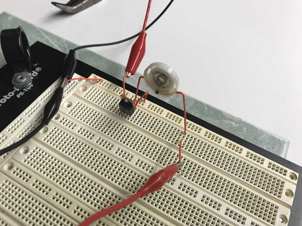
Experimentation set up for the speaker
NEXT>